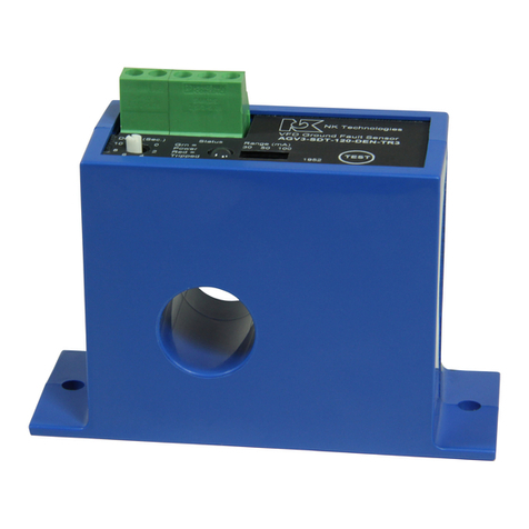
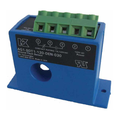
NK TECHNOLOGIES AGL1 Series User manual

INSTRUCTIONS
1. Runallcurrentcarryingconductorsthrough
sensor window
A. Use anauxiliaryCTifconductors do notfit. Consult
Factory for CT selection.
2. Mount the sensor to a surface if needed.
3. Connect output & power wiring.
A. Use up to 14 AWG copper wires.
B. Make sure power and load matches those shown on
the senors’label.
4. Test
A. Pressing the “TEST”button teststhe sensors internal
circuits. CAUTION: The output and any connected
loads will switch!
AGL1 - NOR1 - 120 - LA - 005-N
Model Number KeySpecifications
Know Your Power Quick “How To” Guide
Power Supply Notes
AGL1, 2 & 3 SERIES
Ground Fault Sensors
with Latching Relay Outputs
AGL SeriesLatching. 3.0 06/10, P/N 49-068-0004
Output Type
NOR1 SPST (Normally open, closes on fault)
NCR1 SPST (Normally closed, opens on fault)
Power Supply
24U 24 VAC/DC
120 120 VAC
Setpoint Range
1 5-100mA, Adjustable
2 80-950mA, Adjustable
3 Tri-Set, 5, 10 & 30 mA, Jumper Select
AGL Series Ground Fault Sensor
Options
LA Normally De-energized
Setpoint
005 to 950 Factory Adjusted
Setpoint in mA (specify
when ordering)
TR3 Tri-Set, 5, 10 & 30 mA,
Jumper Select
Setpoint Range AGL1 Series: 5-100mA Field Adjustable
AGL2 Series: 80-950mA Field Adjustable
AGL3 Series: Tri-Set, 5, 10 & 30 mA,
Jumper Select
Voltage Range Up to 1,500 VAC (Monitored Circuit)
Frequency Range 50-400Hz (Monitored Circuit)
Output Description: Electromechanical relay
1.0A @ 120 VAC, 2A @ 30 VDC
Status (Red) LED = Relay has operated
Response Time 200 ms @ 5% over setpoint.
60 ms @ 50% over setpoint.
15 ms @ 500% over setpoint
Power Supply 120 VAC Operates from 66-132 VAC
(50-400hz)
Optional Power 24 VAC or 24 VDC Operates from
19.2-28.8 Volts)
Power (Green) LED=Power supply
energized
Power Consumption 2.5 Watts
Dimensions 4.25”H x 3.0”W x 3.25”D,
(108x76x83mm), aperture 1.82” (46mm)
dia.
Case UL 94V-O Flammability Rated
Environmental 5 to 158 DegF (-15 to 70 DegC), 0-95%
RH, Non Condensing
Terminal torque 5.3 inch-pounds
System Grounding
3511 Charter Park Drive, San Jose, CA 95136Toll free:
800-959-4014, Phone: 408-871-7510
Fax: 408-871-7515
[email protected], www.nktechnologies.com
Know Your Power
Other NK Technologies Products Include:
AC & DC Current Transducers
AC & DC Current Operated Switches
1φ& 3φPower Transducers
Current & Potential Transformers (CTs&PTs)
All low-current Ground-Fault Sensors are sensitive devices
that require reasonable care in system design to avoid false
trips caused by high electrical noise levels. Keep in mind
that the best way to reduce noise in a system is to suppress
it at its source.
1. Keep the sensor power isolated from noisy circuits.
2. Donotpower thesensorwiththesamecircuitthatswitches
contactors or other high current, inductive loads.
Good design practice and code require that all AC power
systems be grounded. AGL Series sensors are designed to
workongroundedAC powersystems. Theymay notoperate
properly on ungrounded systems.
Options
None (Blank)
N Electical Noise Immun.

Description
Operation
Principal of Operation
Under normal conditions, the current in one wire of a two
wire load is equal in strength but opposite in sign to the cur-
rent in the other wire. The two wires create magnetic fields
that cancel, acondition known as“Zero Sum Current”.If any
current leaks to ground (Ground Fault), the two currents be-
come unbalanced and there is a net resulting magnetic field.
The AGL sensor detects this minute field and changes the
output state. This concept extends to three phase systems
such as 3 wire Delta and to 4 wire Wye.
AGLSeries sensors work in the same environment as mo-
tors, contactors, heaters, pull-boxes, and other electrical
enclosures. They can be mounted in any position or hung
directly on wires with a wire tie. Just leave at least one inch
distance between sensor and other magnetic devices. Run
all current carrying conductors through the opening in the
sensor. (See “Principal of Operation”) Be Sure all wires
are oriented so current flows in the same direction.
Installation & Wiring
AGL Series sensors monitor all current carrying wires in
single or three phase systems to detect ground faults. They
provide a contact output that can operate relays, contactors
or signal automation systems.
Wiring
Use up to 14 AWG copper wire and tighten terminals to
5.3 inch-pounds torque. See Diagram.
Power
Connect power wiring to Terminals 3 & 4. Be sure that
the power supply matches the power rating on the sensor
label. Green LED (Power) will light.
Output
Connect output wiring to Terminals 5 & 6.
Reset Switch
Connect a momentarydry contactto the reset terminals(1&
2.) Limit wire run to 200’ of 18 AWG or larger wire.
Momentary Reset
The sensor will not work properly if the reset terminals are
closed (shorted) continuously. Only close thereset terminals
momentarily.
Parallel Reset Connection
Multiple sensors may be connected to the same reset switch
in parallel. Only the sensors that have detected a fault and
have latched will be reset. Asensor will not reset unless the
fault has dropped below setpoint.
AGLSeriesLatchingGroundfaultsensorsoperateinoneof
two states: Reset or Latched. If control power is removed,
the sensor remains in it’s last state (latched or reset). The
sensor will unlatch if the power supply is cycled off and
then on again.
To test operation, gently press the TESTbutton. This simu-
lates a fault and tests the internal switching circuits.
CAUTION: Any circuit connected to the sensor will be
operated.
The normally open contact closes on sensed fault current
over the set point, and the normally closed contact opens
on fault.
Set point adjustment, CW
to adjust higher located
under label
Test button (activates
output relay!)
Red Status LED
(On when tripped)
Green Power LED (On
when powered)
Power Supply
Input (3&4) External Reset
Button (1&2)
When used with an external CT, the sensor will be set to
trip at a point much lower than without the CT. This set
point adjustment should be done with the load passing
through the CT in that application.
Single Phase (Phase
& Neutral or Phase to
Phase)
3 Phase Delta (Include
neutral if the load uses
neutral)
3 Phase Wye (Include
neutral if load uses
neutral)
3 Phase Load, using an auxiliary Current Transformer.
Contact factory for details.
Field Setpoint Adjustment
While not as precise as having it set at the factory, the set
point can be adjusted in the field through use of the small
potentiometer located beneath the label to the right of the
leads exiting the case. Though not receommended, if a
field adjustment of setpoint is desired, the recommended
steps are as follows:
1. Develop a load of the magnitude at which you want
the sensor to trip; e.g., a 4000 ohm resistor at 120 VAC
should provide a load of 30 mA while 4 watt “night light”
bulb would create a load of approximately 3.333 mA.
2. With the load energized and passing through the sens-
ing aperture, turn the potentiometer clockwise (CW) until
the sensor trips. Then turn the pot back (CCW) one eighth
of a turn.
NOTE: The tri-set models cannot be adjusted higher nor
lower than the factory settings.
SUPPLY POWER
24V or 120V
01
02
05 06
03
04
NO OR NC
COMMON
EXTERNAL RESET
OUTPUT CONNECTION
TRIP POINT SELECTION (IF USED)
STATUS LED POWER LED
TEST
TRIP ADJUSTMENT
(UNDER LABEL)
Output Connection
(5 & 6), NO closes
on fault, NC opens
on fault
The triple range, field selectable models use a jumper
to select the trip point. With the jumper off the pins, the
sensor will trip at the lowest set point. The jumper can
be placed over two pins to set the trip point at the me-
dium level, or the other two pins to be set at the highest
trip point.
This manual suits for next models
2
Other NK TECHNOLOGIES Accessories manuals


