4
XP 15 W
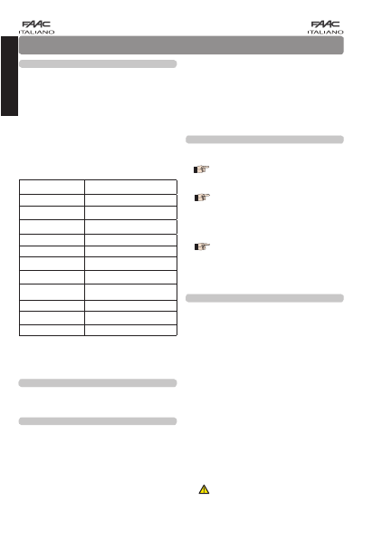
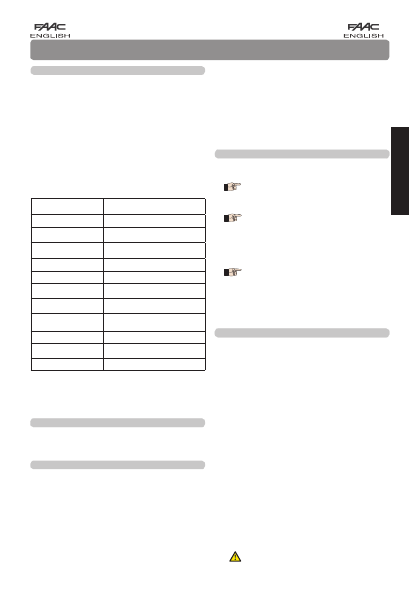
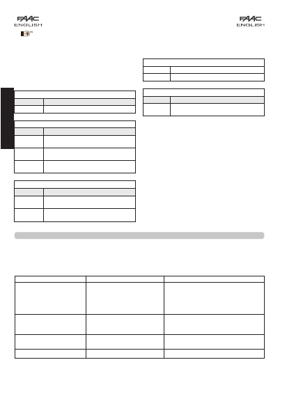
1. DESCRIZIONE E CARATTERISTICHE TECNICHE
ALIMENTAZIONE 12 - 24 V~.
12 - 24 Vdc
ASSORBIMENTO RX 30 mA
ASSORBIMENTO TX 40 A a Batteria
5 mA a 24 Vdc
TIPO E DURATA
BATTERIA TX CR2 DA 3 V
da 2 a 3 anni *
PORTATA MASSIMA 15 m
GRADO DI PROTEZIONE IP54
TEMPO RILEVAMENTO
OSTACOLO 40 ms
MODALITÀ
DI ALLINEAMENTO automatica
ANGOLO DI
AUTOALLINEAMENTO +/- 7° (15 m)
+/- 13° (5 m.)
TRAMISSIONE SEGNALE 4 canali selezionabili
TEMPERATURA DI
FUNZIONAMENTO -20...+55 °C
INSTALLAZIONE a parete o su colonnetta
*La durata della batteria può variare in funzione della carica
della batteria impiegata, della sua tipologia e delle condizioni
ambientali/installative.
La coppia di fotocellule autoallineanti XP15 W è compo-
sta da un trasmettitore ed un ricevitore a raggi infrarossi
sincronizzati a quattro canali selezionabili.
La fotocellula XP15 W è un dispositivo ausiliario alla
sicurezza.
L’oscuramento del fascio luminoso, provoca il cambia-
mento di stato del ricevitore, il quale invia il segnale di
fotocellula impegnata tramite contatto a relè.
Il Trasmettitore della coppia è alimentato a batteria ma
può anche essere alimentato tramite il collegamento
filare.
La selezione del canale di trasmissione permette di installa-
re sullo stesso impianto fino a 4 coppie di XP15 W eliminado
il rischio di interferenze tra una coppia e l’altra.
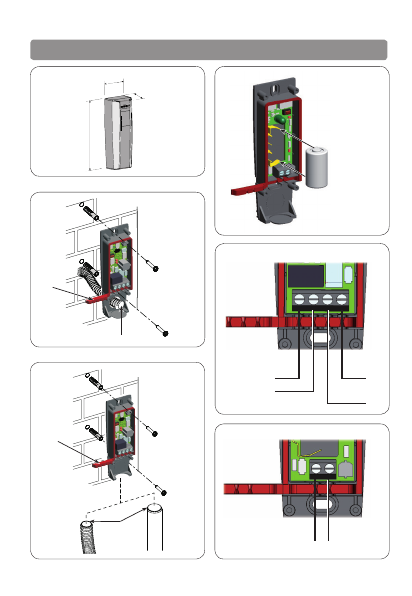
2. DIMENSIONI
3. INSTALLAZIONE
Per un corretto funzionamento, posizionare il Ricevitore e
il Trasmettitore allineati.
Il Ricevitore della coppia XP15 W ha due possibili tipologie
d’installazione:
- A parete con guaina ad incasso (Fig. 2).
- A parete con tubo/guaina esterni (Fig. 3).
•Eseguire le predisposizioni per i collegamenti elettrici.
•Fissare il corpo del ricevitore utilizzando viti e tasselli
idonei.
Le dimensioni del Trasmettitore e del Ricevitore sono le
medesime e sono riportate in Figura 1.
Il Trasmettitore della coppia XP15 W ha la possibilità di es-
sere alimentato tramite la batteria interna (Fig. 4) oppure
tramite collegamento filare.
Il Trasmettitore alimentato a batteria necessita del solo
fissaggio a parete o su colonnetta.
Qualora il Trasmettitore utilizzi l’alimentazione filare, seguire
le stesse tipologie d’installazione indicate nelle figure 2 e
3.
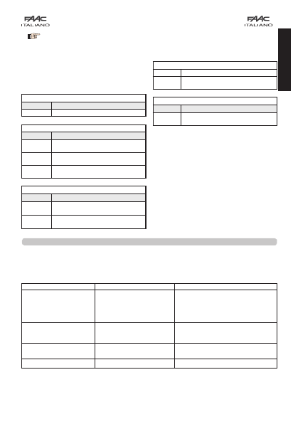
4. COLLEGAMENTI ELETTRICI
Eseguire i collegamenti elettrici sulle morsettiere del rice-
vitore come indicato in Fig. 5.
I morsetti di alimentazione del Ricevitore
possono essere collegati ad una tensione di
12 o 24 Volt sia continua (DC) che alternata
( ~ ).
Qualora si intenda effettuare il controllo FAIL
SAFE con Trasmettitore alimentato a batteria,
collegare il morsetto FAIL SAFE (-TX FSW) delle
schede elettroniche FAAC al morsetto MENO
(_) del Ricevitore fotocellula.
Nel caso si alimenti il Trasmettitore tramite collegamento filare
seguire le indicazioni in Fig. 6.
I morsetti di alimentazione del Trasmettitore
possono essere collegati ad una tensione di
12 o 24 Volt sia continua (DC) che alternata
( ~ ).
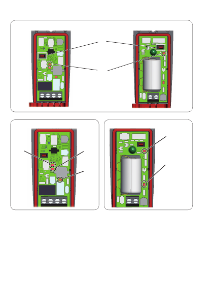
5. MESSA IN FUNZIONE
Prima di chiudere la coppia di fotocellule con i rispettivi
coperchi, è indispensabile selezionare il canale di trasmis-
sione e controllarne il funzionamento attraverso i LED di
segnalazione presenti sul Ricevitore.
SELEZIONE CANALE DI TRASMISSIONE
Alimentare le fotocellule e selezionare il canale di trasmis-
sione PREMENDO E MANTENEDO PREMUTO PER 5 SECONDI
il pulsante P1 (fig.7).
Al termine dei 5 secondi il led DL2 in figura 7 lampegge-
rà un numero di volte pari al canale impostato per poi
spegnersi 1 secondo e ripetere la segnalazione. Dopo
aver completato 3 segnalazioni del canale impostato la
procedura è terminata ed il canale è memorizzato.
Durante questa visualizzazione è possibile cambiare il ca-
nale di trasmissione: tramite la pressione del pulsante P1
si selezionano in successione i quattro canali.
Controllare il numero di lampeggi del led DL2 per deter-
minare quale canale si è selezionato:
1 lampeggio = Canale 1
2 lampeggi = Canale 2
3 lampeggi = Canale 3
4 lampeggi = Canale 4
Impostare lo stesso canale sia sul ricevitore
che sul trasmettitore.
All’accensione del Trasmettitore e del Ricevitore i rispettivi
led DL2 si accendono per 1 secondo.
ITALIANO