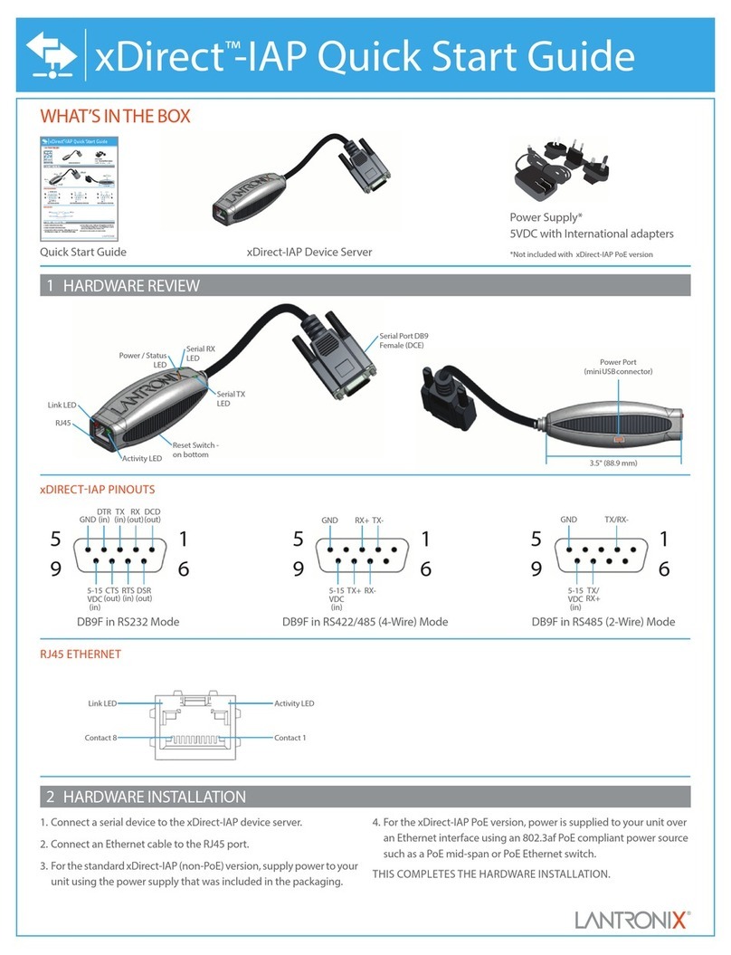
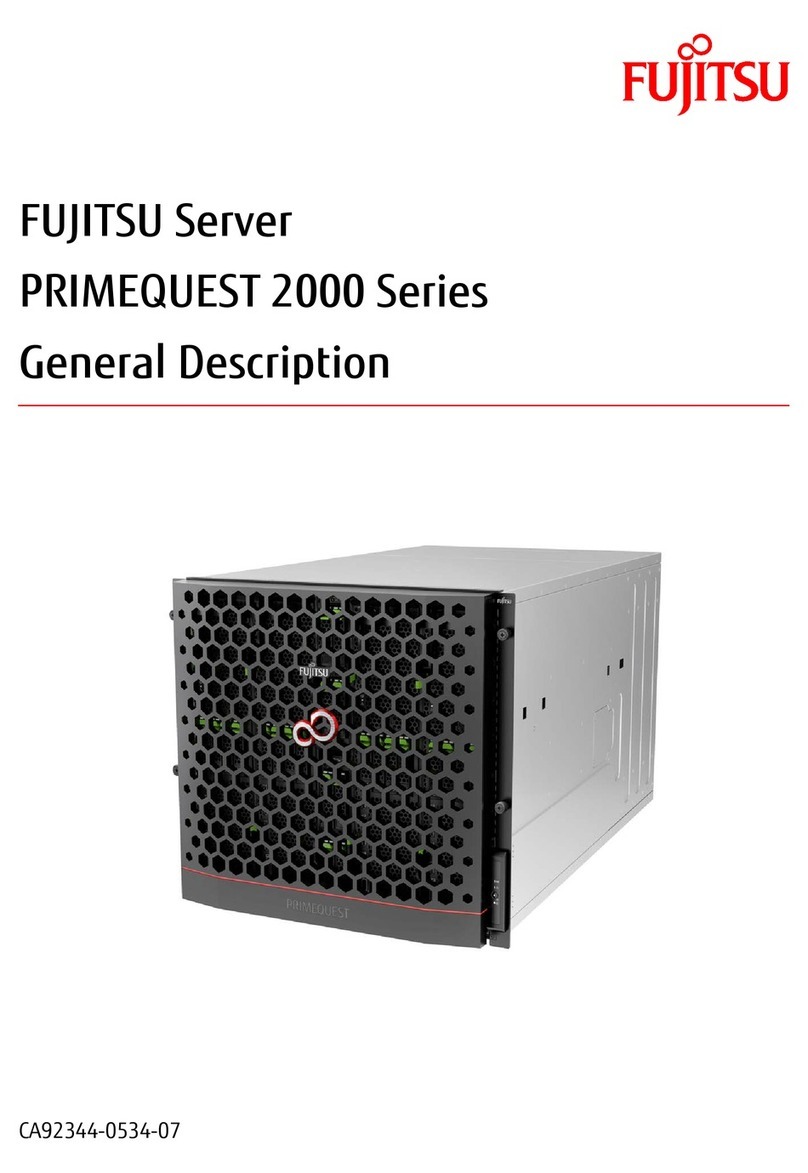
Obvius AcquiSuite A8820 User manual

AcquiSuite
USB
24VDC, 500mA
Internet
Modbus RTU Devices
(RS485-1)
Modbus RTU Devices
(RS485-2)
Ethernet Connected Meters & Devices
(Ethernet-2)
Computer may also be directly
connected to the A8820
120 ohm 120 ohm 120 ohm120 ohm
SS
+-
+-S S
SS
++
--SS
+
-
++ +
-- -
Ethernet Router/Switch (Cat 5/Cat6) Ethernet Router/Switch (Cat 5/Cat6)
USBENET-1
STATUS
RX
RS485-2
SHIELD
TXRX
RS485-1
TX
Enter
ENET-2
A8820
+-
24 VDC @
500mA
+-
SHIELD
+-
Computer
AcquiSuite
USB ENET-1
STATUS
RX
RS485-2
SHIELD
TXRX
RS485-1
TX
Enter
ENET-2
A8820
+-
24 VDC @
500mA
+-
SHIELD
+-
AcquiSuiteTM Data Acquisition Server
Cat. No. A8820
INSTALLATION GUIDE ENGLISH
DI-602-A8820-00A
NOTICE:
• This product is not intended for life safety applications.
• DO NOT install this product in hazardous or classified locations.
• The installer is responsible for conformance to all applicable codes.
• The device must be installed following the guidelines set forth in this installation guide,
or the inherent protection provided by the device may be compromised.
Product Application Limitation
• Obvius products are not intended for use in critical applications such as nuclear facilities,
human implantable devices or life support. Obvius is not liable, in whole or in part, for any
claims or damages arising from such uses.
• Obvius strongly believes in continuous improvement, therefore we must reserve the right
to change specifications and product offerings without notice. Where possible, we will
substitute products with equivalent functionality when necessary.
1. Unpack materials.
2. Mount the DAS using either the DIN rail mount, or with screws through the mounting tabs.
3. Optional: Connect the Modbus network loop as shown in the diagram. Follow the
manufacturer’s instructions for installing and powering the Modbus devices.
4. Connect a PC to the DAS using a Cat 5 or better ethernet cable.
a. ENET 1 should be the "upstream" connection to the Internet. Connect it to your
firewall/router or Ethernet modem.
b. ENET 2 should be the "downstream" connection, for your PC and for Ethernet meters
and devices.
5. Supply +24VDC to the DAS. Once power is applied, the Status LED will immediately turn
on and the LCD will show a series of progress messages as the system boots.
6. Decide type of connection:
a. DHCP Mode (DHCP is the default and is recommended).
b. Static IP Mode.
SPECIFICATIONS
Power 24VDC, 500mA max
Pollution Degree 2
Operating Temperature -30°C to +70°C, 95% RH non-condensing
Communication Protocols Modbus RTU, Modbus TCP, TCP/IP, HTTP, HTML, FTP
LAN Dual (2x) RJ45, 10/100 Ethernet
USB USB 2.0 Type A
RS485 Dual (2x) RS485 Modbus, each supporting up to 32 external
devices (64 total)
Torque Settings
(Wiring Terminals)
Min = 4.4 in/lb (0.5 NM)
Max = 5.3 in/lb (0.6 NM)
Overview
AcquiSuite is a family of data acquisition
systems that provides owners and managers of
commercial and industrial facilities with a cost-
effective means of gathering crucial information
in a timely manner.
The footprint and industrial temperature range
makes this a perfect solution for embedded
applications. Reduce development time
and speed up integration by collecting and
distributing energy and sensor data directly
from your equipment.
Installation Checklist
Hardware:
• A8820 AcquiSuite Data Acquisition Server (DAS)
• Laptop (not provided) with one RJ45 port (required for LAN or direct
laptop-to-DAS connection)
• Ethernet Cat 5 or better ethernet cable (not provided)
• Power Supply 24VDC, 500mA or greater (not provided)
Optional hardware:
• Additional ModbusTM Devices
• 2 wire, twisted pair with shield for Modbus/RS485 connection
(BeldenTM 1120A or equivalent)
• Termination resistors (120 ohm) for long RS485 runs over 200 ft
• When installed in an outdoor or harsh environment, the device must be mounted in an
appropriate listed outdoor or industrial rated enclosure (Type 4X / IP54 in Europe).
• Only copper wiring is to be used for all field wiring terminals.
Mounting
DIN Rail: The A8820 is designed with integrated DIN rail mounting clips for a standard
35 mm DIN rail. The integrated clips on the back of the enclosure will snap directly on the rail.
Mounting Tabs: The enclosure provides mounting tabs in each corner of the enclosure. Use
the appropriate type #6 or smaller screw to attach the unit to the mounting surface.
Mounting Template
(Dimensions)
Mounting Installation
DHCP Enabled Mode
Confirm the DAS is properly connected to the computer or a LAN, and that both are
powered ON.
Single Ethernet and Modbus (RS485)
Dual Ethernet and Modbus (RS485)
1. Confirm that DHCP is enabled on the computer. For most computers, this is the
default setting.
2. From the device front panel, navigate to the Quick Start menu. The first screen in the
Quick Start will display the IP addresses for active Ethernet connections. Be sure to use
the IP address for the correct Ethernet port, if both ports are connected. The device must
be connected to the same network that the PC is connected to.
3. Open a browser and type the IP address, as shown on the LCD display of the AcquiSuite,
in the address bar.
4. This will open the web browser interface of the AcquiSuite.
5. At initial setup, a password must be created. Select “Click here for Password Setup” to
create the admin user password.
6. Enter the desired admin user password in both boxes and select "Apply."
7. A message confirming that the password was successfully set will display. Select the link
below it to proceed to the login screen.
AcquiSuite
USB
24VDC, 500mA
Internet
Modbus RTU Devices
(RS485-1)
Enet 1 preferred
Computer may also be directly
connected to the A8820
120 ohm 120 ohm
SS
+-
+-S
S
+-
+-
Ethernet Router/Switch (Cat 5/Cat6)
Enet 2 optional
USBENET-1
STATUS
RX
RS485-2
SHIELD
TXRX
RS485-1
TX
Enter
ENET-2
A8820
+-
24 VDC @
500mA
+-
SHIELD
+-
Computer
+-
4.61 in.
3.76 in. 3.76 in.
4.87 in.
5.19 in.

FOR CANADA ONLY
For warranty information and/or product returns, residents of Canada should contact Obvius in writing to the attention of the Obvius Quality Assurance Department, 20497 SW Teton Avenue, Tualatin, OR 97062 or by telephone at 1-503-601-2099
© 2021 Obvius Holdings, LLC
For Technical Assistance Call Phone: 503-601-2099
Toll Free: 1-866-204-8134 (USA only) Fax: 503-601-6878
Trademark Disclaimer
Use herein of third party trademarks, service marks, trade names, brand names and/or product names are for informational purposes only,
are/may be the trademarks of their respective owners; such use is not meant to imply affiliation, sponsorship, or endorsement. Modbus is a
U.S. registered trademark of Schneider Electric USA, Inc. Belden is a trademark of Belden, Inc.
IC Statement:
This device complies with Industry Canada license-exempt RSS standard(s). Operation is subject to the following two conditions: (1) this
device may not cause interference, and (2) this device must accept any interference, including interference that may cause undesired
operation of the device.
Front Panel Setup - DHCP Mode
1. From the main menu, select the "Quick Start."
3. If Ethernet port 1 is not set to DHCP mode, select Enet 1 and then "Network Mode" to
open the Network Mode Port 1 menu. Then select "Use DHCP."
2. Confirm that Ethernet port 1 (Enet 1) is set to DHCP mode. DHCP is the default mode.
When connected, the IP address will be displayed for each connected port.
Front Panel Setup - Static IP Mode
1. From the main menu, select "Quick Start."
6. Follow the same procedure to set the "Subnet Mask" and "Gateway Address" fields.
2. Select Ethernet port 1 (Enet 1) to open the Ethernet Port 1 menu.
Creating a Password at Initial Setup
1. At initial setup, a password must be created. Select “Click here for Password Setup” to
create the admin user password.
2. Enter the desired admin user password in both boxes and select "Apply."
3. A message confirming that the password was successfully set will display. Select the link
below it to proceed to the login screen.
Logging in with Username and Password
1. From the web browser interface, select “Click here to enter.”
2. Enter the username and password.
3. Login is successful.
3. Select "Network Mode" and then select the "Use Static IP" from the Network Mode
Port 1 menu.
4. Return to the Ethernet Port 1 menu and select "IP Address" to update the IP address to
the desired static IP settings.
5. From the IP address screen, use the left and right arrow keys to navigate through the
number fields, and the up and down arrow keys to scroll through the numbers. With the
full IP address selected, click the OK (Enter) to save.
LIMITED 5 YEAR WARRANTY AND EXCLUSIONS
Obvius warrants to the original consumer purchaser and not for the benefit of anyone else that this product at the time of its sale by Obvius is free of defects in materials and workmanship under normal and proper use for two years from the purchase date. Obvius’s only obligation is to correct
such defects by repair or replacement, at its option. For details visit www.obvius.com or call 503-601-2099. This warranty excludes and there is disclaimed liability for labor for removal of this product or re-installation. This warranty is void if this product is installed improperly or in an
improper environment, overloaded, misused, opened, abused, or altered in any manner, or is not used under normal operating conditions or not in accordance with any labels or instructions. There are no other or implied warranties of any kind, including merchantability and fitness for
a particular purpose, but if any implied warranty is required by the applicable jurisdiction, the duration of any such implied warranty, including merchantability and fitness for a particular purpose, is limited to two years. Obvius is not liable for incidental, indirect, special, or consequential
damages, including without limitation, damage to, or loss of use of, any equipment, lost sales or profits or delay or failure to perform this warranty obligation. The remedies provided herein are the exclusive remedies under this warranty, whether based on contract, tort or otherwise.
FCC STATEMENT:
This equipment has been tested and found to comply with the limits for a Class A digital device, pursuant to part 15 of the FCC Rules.
These limits are designed to provide reasonable protection against harmful interference when the equipment is operated in a commercial
environment. This equipment generates, uses, and can radiate radio frequency energy and, if not installed and used in accordance with the
instruction manual, may cause harmful interference to radio communications. Operation of this equipment in a residential area is likely to
cause harmful interference in which case the user will be required to correct the interference at his own expense.
Any changes or modifications not expressly approved by Obvius Holdings, LLC could void the user’s authority to operate the equipment.
FCC Suppliers Declaration of Conformity (sDoC):
This device manufactured by Obvius Holdings, LLC 20497 SW Teton Avenue,Tualatin, OR 97062 http://www.obvius.com. This device
complies with part 15 of the FCC Rules. Operation is subject to the following two conditions: (1) This device may not cause harmful
interference, and (2) this device must accept any interference received, including interference that may cause undesired operation.
Other Obvius Server manuals

Obvius
Obvius AcquiSuite EMB A8810 User manual

Obvius
Obvius AcquiLite EMB User manual

Obvius
Obvius A8812 User manual

Obvius
Obvius AcquiSuite+ A8814 User manual

Obvius
Obvius A8810-GSM User manual

Obvius
Obvius AcquiSuite A8810 User manual

Obvius
Obvius AcquiLite EMB A7810 User manual

Obvius
Obvius AcquiSuite A8810-0 User manual
Popular Server manuals by other brands

Digital Watchdog
Digital Watchdog Blackjack E-Rack Series quick start guide

Moxa Technologies
Moxa Technologies NPort IA5450A Quick installation guide

Technics
Technics STG30LE operating instructions

Sun Microsystems
Sun Microsystems Sun Fire X4170 installation guide

Dell
Dell PowerEdge 2400 Activation guide

SpectraLink
SpectraLink DECT Server 2500 manual