OCEANAIRE OPACH4212 Manual

OUTDOOR PORTABLE HEAT PUMP WITH FRAME
ENGINEERING, INSTALLATION AND SERVICE MANUAL
OCEANAIRE, Inc.
1731 Wall Street, Suite 100 Mount Prospect, IL 60056
(847) 583-0311 oceanaire-inc.com OA-EISM-OPACH4212- REV. 04062023

Model Number:
MODEL: OPACH4212
Page 3 General Information
Page 4 Specifications
Page 5 OPACH4212 Details
Page 6 Set Up Guidelines
Page 7 Controls/Components
Page 8 Wiring Diagram
Page 9 Start-Up and Operation
Page 10 Troubleshooting Guide
Page 11 Product Warranty
FORWARD
This manual provides the user with basic details for the installation and operation of the
OceanAire OPACH4212 Outdoor Portable Heat Pump. It is highly recommended to read
and fully understand the instructions outlined within this manual, before operating the
OPACH4212 unit.
As with all commercial air conditioning equipment, it is recommended to have the OPACH4212
sized and installed by a licensed specifying engineer and contractor, in accordance with all
local and state codes. The length of service received can be extended by following the
installation instructions and adhering to a preventive maintenance program consistent with
outdoor equipment of this type.
NOTICE
In our ongoing process of continuous improvement, the items and procedures described in this
manual are subject to change without notice. To communicate with us more effectively, please
note model and serial number of the unit before contacting the factory with questions and inquiries.
TABLE OF CONTENTS
OA-EISM-OPACH4212- REV. 04062023
Page 2

Model Number:
MODEL: OPACH4212
GENERAL INFORMATION
The Oceanaire OPACH4212 is an outdoor portable heat pump designed for temporary
cooling and heating applications. With 3.5 tons of cooling capacity the OPACH4212
can deliver cooling for almost any industrial application. With 38,000 BTUH of Heating capacity,
and 7 KW Auxiliary Electric Heat, the OPACH4212 can heat a defined space as well.
The unit is designed for industrial applications. The heavy-gauge 2” x 2” powder coated steel
frame safeguards the unit from its surroundings, and aids with handling and storage. 8-inch
swivel casters allow for improved mobility and maneuvering on job sites. Two of the swivel
casters are equipped with rotational pin-locks, while the other two swivel casters are equipped
with brakes for the securing the unit on-site as well as for storage and transit.
The Power Connection, Main Breaker and duct connections are all located on the left side of the
unit for quicker installation and set-up. All electrical receptacles are equipped with weather proof
covers. The 12-inch supply and return air collars are located on the same side to accomodate
access to the controlled space. The Drain tube is located on the lower right side of the
unit. The Drain Tube with P-trap is outfitted with a 3/4” MGHT connector for hose connection
purposes. The unit is equipped with a storage compartment for the thermostat/cable assembly.
HANDLE
75.5” LENGTH WITH HANDLE
49-1/2”
8-INCH
SWIVEL CASTER
WITH ROTATIONAL
PIN LOCK
OPACH4212 LEFT SIDE
8-INCH
SWIVEL CASTER
WITH BRAKE
2” X 2” WELDED
IRON FRAME
42”
OPACH4212 FRONT
GENERAL DESCRIPTION
FORKLIFT POCKETS
HVDRHVDR
OA-EISM-OPACH4212- REV. 04062023
Page 3

Cooling Capacity:
Voltage: 208-230V, 60Hz, 1PH
Amps: 31.8
Total Watts: 3780
Cooling Ambient: Operating Range
25° to 115°
Cooling Capacity: Total BTUH at 80°DB/67°WB
Return air, 95°F Outdoor
EER: 11.6
Compressor: Scroll
Compressor HP: 3.5
Evaporator CFM - High: 1200
Forward Curved Blower
Evaporator Motor: 1/2-HP
Condenser Fan: Propeller
COND CFM: 1750
Condenser Motor: 1/4 HP
Condensate Removal: Gravity Drain
Refrigerant Charge: 132 ozs. R-410A
Height: 49.5˝
Width: 75.5˝ with handle
Depth: 42˝
Net Weight: 670 lbs.
*Specifications subject to change without notice
Compressor RLA:
Compressor LRA:
17.9
112
TECHNICAL SPECIFICATIONS
Blower Type:
•
PRODUCT FEATURES
REFRIGERATION
3.5 Ton Scroll Compressor
Integrated Compressor Protection
Low Pressure and High Pressure Cut-Out
AUXILIARY HEAT
7 KW Electrical Heat for Low Temp Operation
ELECTRICAL
Locking 250V Power Connection Receptacle
50 Amp Circuit Breaker for Unit Power Protection
40 Amp Auxiliary Heat Breaker
24 VAC Thermostat with 50 ft. detachable cable
Automatic Defrost Modes (in Heating) 30/60/90 minutes
Automatic Heat Mode Change Over from HP to Aux. Heat
BLOWER/FILTERS
Multi-Speed ECM Evaporator Blower
Static Capability Up to 0.7” ESP
Totally Enclosed Condenser Fan Motor
CABINET
49” Tall x 42” Wide Profile
2 x 2 Steel Frame with Handle and Fork Pockets
Wheel Pockets in Frame for Yard Storage (3 high - Maximum)
8-Inch Urethane Swivel Casters
Two Swivel with Rotational Locking Pins
Two Swivel with Brakes
DUCT PANELS
Supply: 1 x 12” Dia. Duct Collar
Return: 2 x 12” Dia. Duct Collar with integral Return Air Filter Frame
Filter: (1) 14 x 25 x 1, Pleated
DRAIN
P-Trap with 3/4” Male Garden Hose Connector
40,500 BTUH
Heating Capacity (HP): 37,600 BTUH
Model Number:
MODEL: OPACH4212
3.5 Ton Outdoor Portable
Heat Pump with Auxiliary Heat
Aux. Heat Capacity: 7 KW
OA-EISM-OPACH4212- REV. 04062023
Page 4

Model Number:
MODEL: OPACH4212
POWER INLET
(50 AMP - 250VAC)
SUPPLY AIR
(12-INCH COLLAR) RETURN AIR (2 X 12-INCH COLLAR)
FILTER ACCESS PANEL (TOP OR SIDE)
MAIN
BREAKER BOX
OPACH4212 LEFT SIDE
OPACH4212 DETAILS
THERMOSTAT
STORAGE
COMPARTMENT
OPACH4212 REAR
CONTROLS
ACCESS PANEL
EVAP BLOWER
ACCESS PANEL
THERMOSTAT
CABLE
RECEPTACLE
NOTE: THE AUXILIARY ELECTRIC HEATER SAFETY BREAKER IS
LOCATED BEHIND THE EVAP BLOWER ACCESS PANEL
OA-EISM-OPACH4212- REV. 04062023
Page 5

CONNECT ONLY TO POWER SOURCE AS SPECIFIED ON UNIT NAMEPLATE
1. Set up the OPACH4212 unit on a level surface. Make sure that there are no objects on top of
the unit. Maintain an operating clearance of 3 feet minumum on all sides of unit.
2. Remove Thermostat Assembly from Storage Compartment, and unwind the Thermostat Cable.
3. Locate Thermostat Cable Receptacle, remove the cover and connect the Thermostat Cable to the unit.
4. Connect Drain Hose using to the 3/4” MGHT Connector, and route drain hose away from unit to a
drain ro sfae run-off location
5. Connect Power Cord to unit using the locking 250 VAC Receptacle
POWER INLET: Hubbell # CS8275 POWER CONNECTOR: Hubbell # CS8264C, or Equivalent
6. Check that all power connections are secure, and that the Main Breaker is ON (up position).
7. Connect Supply Power at Source and observe the thermostat display.
8. To Power OFF the unit, set the thermostat in the OFF position
10. Once the unit has shut down, it is safe to disconnect the POWER SUPPLY.
Model Number:
MODEL: OPACH4212
THERMOSTAT
RECEPTACLE
(CLOSED)
THERMOSTAT
RECEPTACLE
(OPEN)
MAIN POWER BREAKER
(COVER OPENED)
POWER INLET
(WITH COVER REMOVED)
Hubbell CS8275
THERMOSTAT ASSEMBLY
STORAGE COMPARTMENT
SET UP GUIDELINES
OPACH4212 DRAIN WITH
3/4” MGHT CONNECTOR
OA-EISM-OPACH4212- REV. 04062023
Page 6

DEFROST
CONTROL
AUX. HEATER
CIRCUIT BREAKER (40A)
Model Number:
MODEL: OPACH4212
EVAP MOTOR POWER CONNECTOR - PLF
(SEE NOTE 2 ON WIRING DIAGRAM)
EVAPORATOR
BLOWER MOTOR
TRANSFORMER COMPRESSOR
CONTACTOR
CAPACITOR HIGH VOLTAGE
POWER BLOCK
THERMOSTAT
CABLE
RECEPTACLE
OPACH4212 CONTROLS
OA-EISM-OPACH4212- REV. 04062023
Page 7

Model Number:
MODEL: OPACH4212
LPS
1 2 3
240208
C
TR
24V
HVDR
LVDR
CCR
R
R
C
C
C
CNT
0
0
0-RV
C-RV
W
Y
Y
PS2
DF1
DF2
DFT
R-DFT
R-PS1
C
L
G
N
12 3 45
DFT
RVC
HPS
CM
COMP
S
C
R
H
C
F
369
258
147
RCCF
C
O/B
W1
G
R
Y1
YL
RD
GR
WH
OR
BR
BL
LVJB
SEE NOTE 4
GND
T2 L2
L1
T1
SEE NOTE 5
SEE NOTE 6
SEE NOTE 3
SEE NOTE 1
YL/PK
YL/PK
PU
BK
PU
RD
BK
PU
RD
BK
BK
PU
PU
RD
RD
OR
BL
GR
GR
PU
PU
OR
BL
BL
RD
YL
YL
BK
PU
GR
BL
GR
YL
YL
YL
YL PU
GR
WH
WH
WH
BK
BK
WH
YL
RD
SEE NOTE 2
EM
YL
RD
BR
PLF
BL
BR
PU
BR
BK
BL/PK
BL/PK
BK
BRPU
YL
CONTACTOR
COMPRESSOR CONTACTOR RELAY
CONDENSER MOTOR
COMPRESSOR
DEFROST CONTROL
DEFROST THERMOSTAT
EVAPORATOR MOTOR
EQUIPMENT GROUND
HIGH VOLTAGE DEFROST RELAY
LOW PRESSURE SWITCH
LOW VOLTAGE DEFROST RELAY
LOW VOLTAGE JUNCTION BOX
FEMALE PLUG / CONNECTOR (IN HEATER BOX)
REVERSING VALVE COIL
RUN CAPACITOR FOR COMPRESSOR AND FAN
TRANSFORMER
HIGH PRESSURE SWITCH
NOTES:
1. REPLACEMENT WIRE MUST BE SAME SIZE AND TYPE INSULATION AS ORIGINAL
(AT LEAST 105°C) USE COPPER CONDUCTOR ONLY.
2. TO CHANGE EVAPORATOR MOTOR SPEED IN COOLING MODE, MOVE YELLOW LEAD
FROM EM" 4” TO "2"
3. FOR 208 VOLT TRANSFORMER OPERATION MOVE PURPLE WIRES FROM
TERMINAL 3 TO TERMINAL 2 ON TRANSFORMER.
4. USE COPPER CONDUCTORS ONLY. USE N.E.C. CLASS 2 WIRE.
5. DOUBLE POLE CONTACTOR SHOWN. SINGLE POLE CONTACTOR COULD BE
FACTORY EQUIPPED AS AN ALTERNATE CONFIGURATION.
6. COMMON SIDE OF CONTACTOR CAN NOT BE GROUNDED OR CONNECTED TO
ANY OTHER COMMON (24V).
COMPONENT LEGEND
C
CCR
CM
COMP
DC
DFT
EM
GND
HVDR
LPS
LVDR
LVJB
PLF
RVC
RCCF
TR
HPS
FACTORY WIRING
LINE VOLTAGE
LOW VOLTAGE
WIRE CODE
BK
BL
BR
GR
OR
PU PURPLE
RD RED
WH WHITE
YL YELLOW
POWER INLET - CS8275
208-240V/1/60Hz
MAIN BREAKER
50 AMP
USE CONNECTOR
HUBBELL - CS8264C
OR EQUIVALENT
T2
L2 L1
T1
HTR 1 HTR 2
FLS
FLS
TL
TL
AUX HTR
BREAKER
40 AMP
AUX HTR
CONTACTOR
BL
OR
OR/WH
GR
BL/WH
GR/WH
S1
S2
BR
BR/WH
OAS
6
4
PLUGGED INTO
TERMINALS
4 & 6 ON PLF
BL
WH
CAT 8
CABLE
PRS6110
THERMOSTAT
BR/WHBR
OUTDOOR AIR TEMP SENSOR
OAS
ELECTRIC HEAT ELEMENT
HTR
BR/WH
BLACK
BLUE
BROWN
BROWN/WHITE
GREEN
ORANGE
OR/WH ORANGE/WHITE
GR/WH GREEN/WHITE
BL/WH BLUE/WHITE
RD
THERMAL LIMIT
TL
LIMIT SWITCH
FLS
HVPB
HIGH VOLTAGE POWER BLOCK
HVPB
OPACH4212 WIRING DIAGRAM
CCR
DC
LOW VOLTAGR
BROWN LEAD
NOT USED
OA-EISM-OPACH4212- REV. 04062023
Page 8

Powering and Starting the Unit - Follow the Instructions on Page 6 of this manual.
1. Make sure that the power supplied to the OPACH4212 unit matches the power shown on the
unit nameplate, and that all power connections are correct and secured.
NOTE: Connecting the unit to an incorrect or faulty power source will void the warranty
2. Engage the MAIN POWER. The unit is now controlled by the thermostat.
Cooling Mode
Begin by pressing the SYSTEM button until the thermostat is in COOL Mode. Using the
ARROW buttons, set the desired space temperature setpoint. Remember, cooling will begin
once the space temperature has risen 3 degrees above the set point.
NOTE: The minimum setpoint in Cooling Mode is 55 degrees F
Heating Mode
Begin by pressing the SYSTEM button until the thermostat is in HEAT Mode. Using the
ARROW buttons, set the desired space temperature setpoint. Remember, heating will begin
once the space temperature has fallen 3 degrees below the set point. When in Heat Mode,
the thermostat determines the heating operation according to a preprogrammed switch-over
temperature.
When in HEAT mode, the unit will operate in Heat Pump mode until the outdoor temperature
falls below the preprogrammed limit of 50 degrees. The unit will automatically switch to
Electric Auxiliary Heat until the outdoor temperature rises above 50 degrees.
Fan Mode
Pressing the FAN button, allows the user to switch Fan Modes from AUTO to ON. In AUTO
Mode, the fan will turn on and off as the unit cycles in Cooling or Heating Mode. In ON Mode,
the fan will run continuously.
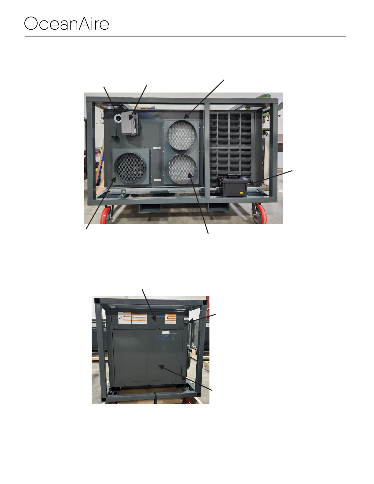
Circuit Breakers
The unit and the Auxiliary Heat Module are protected by line power circuit breakers.
The unit breaker will trip at 50 Amps, while the Auxiliary Heat Module is protected by a separate
40 Amp breaker, located behind the Blower Cover Panel. The control access cover and blower
access panel will need to be removed to gain access to the heater breaker as shown on Page 7.
Model Number:
MODEL: OPACH4212
OPACH4212 START UP AND OPERATION
OA-EISM-OPACH4212- REV. 04062023
Page 9

Model Number:
MODEL: OPACH4212
OPACH4212 Troubleshooting Guide
Start Up
Thermostat Display will not Illuminate
Check Incoming Power. Correct power supplied to unit.
Check MAIN Breaker and reset it, if needed.
Check the Thermostat Cable Connection at the unit. Re-seat the connector.
Thermostat works, Not Cooling
Check the thermostat to see if in COOL mode.
Check the thermostat to see if the setpoint is three degrees lower than the space
temperature. Adjust the setpoint if needed, or wait until the space warms.
Check the incoming power for proper voltage plus the proper amperage to start
the compressor. If not, contact an electrician.
Thermostat works, Not Heating
Check the thermostat to see if in HEAT mode.
Check the thermostat to see if the setpoint is three degrees higher than the space
temperature. Adjust the setpoint if needed, or wait until the space cools.
Check the incoming power for proper voltage plus the proper amperage to start
the compressor. If not, contact an electrician.
If outdoor temperature is below 50 degrees, remove the controls access panel and the
blower access panel, and check the Aux. Heater Breaker. Breaker will display RED
when tripped. Reset the breaker. The breaker will display GREEN when on.
OA-EISM-OPACH4212- REV. 04062023
Page 10
TROUBLESHOOTING GUIDE

LIMITED WARRANTY
The Manufacturer (Oceanaire, Inc.) warrants to the original owner that the Product will be free from defects in
material or workmanship for a period not to exceed one (1) year from date of installation. If upon examination by
the Manufacturer, the Product is shown to have a defect in material or workmanship during the warranty period,
the Manufacturer will repair or replace, at its option, that part of the Product which is shown to be defective.
The Manufacturer further warrants that the product's compressor-motor will be free from defects in materials and
workmanship for one year from the date of installation.
If upon examination by the Manufacturer the Product is shown to have a defect in materials or workmanship
during the warranty period, the Manufacturer will repair or replace, at its option, that Part of the Product which is
shown to be defective. Electrical parts such as relays, overloads, capacitors, etc., and the sealed refrigeration
system (condenser and evaporator) are included in the one-year limited warranty, but not with the five-year
limited warranty of the compressor.
This limited warranty does not apply to:
a) Product that has been subjected to misuse or neglect, has been accidentally or intentionally damaged,
has not been installed, maintained or operated in accordance with the furnished written instructions, or
has been altered or modified in any way.
b) Product that has been subjected to any abnormal power conditions such as loss of power, power
surges, voltage irregularities such as brown-outs or phase loss (on three-phase equipment).
c) any expenses, including labor or material, incurred during removal or reinstallation of the Product.
d) any workmanship of the installer of the Product.
This limited warranty is conditional upon:
a) return to the Manufacturer, of the part of the Product thought to be defective.
Goods can only be returned with prior written approval from the Manufacturer.
All returns must be freight prepaid.
b) determination in the reasonable opinion of the Manufacturer, that there exists a defect in material or
workmanship.
Repair or replacement of any part under this Limited Warranty shall not extend the duration of the warranty with
respect to such repaired or replaced part beyond the stated warranty period.
THIS LIMITED WARRANTY IS IN LIEU OF ALL OTHER WARRANTIES, EITHER EXPRESSED OR IMPLIED,
AND ALL SUCH OTHER WARRANTIES, INCLUDING WITHOUT LIMITATION IMPLIED WARRANTIES OF
MERCHANTABILITY OR FITNESS FOR A PARTICULAR PURPOSE, ARE HEREBY DISCLAIMED AND
EXCLUDED FROM THIS LIMITED WARRANTY. IN NO EVENT SHALL THE MANUFACTURER BE LIABLE
IN ANY WAY FOR ANY CONSEQUENTIAL, SPECIAL, OR INCIDENTAL DAMAGES OF ANY NATURE
WHATSOEVER, OR FOR ANY AMOUNTS IN EXCESS OF THE SELLING PRICE OF THE PRODUCT OR ANY
PARTS THEREOF FOUND TO BE DEFECTIVE. THIS LIMITED WARRANTY GIVES THE ORIGINAL OWNER
OF THE PRODUCT SPECIFIC LEGAL RIGHTS. YOU MAY ALSO HAVE OTHER RIGHTS WHICH MAY VARY
BY EACH JURISDICTION.
OA-EISM-OPACH4212- REV. 04062023
Page 11
Model Number:
MODEL: OPACH4212
WARRANTY
Table of contents
Other OCEANAIRE Heat Pump manuals
Popular Heat Pump manuals by other brands

Dimplex
Dimplex SI 5MER Installation and operating instructions

Hitecsa
Hitecsa Industrial Series Installation, operation & maintenance manual

GE
GE AJHS10DCB Dimension Guide

evoheat
evoheat EVO 270 manual

Immergas
Immergas Magis Combo Series Instructions and warnings

Fairland
Fairland IPHC150T Installation & user manual