manuals.online logo
Brands
  1. Home
  2. •
  3. Brands
  4. •
  5. Oceanic
  6. •
  7. Diving Instrument
  8. •
  9. Oceanic VT Pro User manual

Oceanic VT Pro User manual

Other Oceanic Diving Instrument manuals

Oceanic Pro Plus User manual

Oceanic

Oceanic Pro Plus User manual

Oceanic Prodigy User manual

Oceanic

Oceanic Prodigy User manual

Oceanic Dive Computer Pro Plus 2 User manual

Oceanic

Oceanic Dive Computer Pro Plus 2 User manual

Oceanic GEO User manual

Oceanic

Oceanic GEO User manual

Oceanic GEO User manual

Oceanic

Oceanic GEO User manual

Oceanic GEO 2 User manual

Oceanic

Oceanic GEO 2 User manual

Oceanic ATOM 2.0 User manual

Oceanic

Oceanic ATOM 2.0 User manual

Oceanic VEO 3.0 User manual

Oceanic

Oceanic VEO 3.0 User manual

Oceanic Datamask User manual

Oceanic

Oceanic Datamask User manual

Oceanic DataMax Pro User manual

Oceanic

Oceanic DataMax Pro User manual

Oceanic Veo 180Nx User manual

Oceanic

Oceanic Veo 180Nx User manual

Oceanic XTC-100 User manual

Oceanic

Oceanic XTC-100 User manual

Oceanic VEO 1.0 User manual

Oceanic

Oceanic VEO 1.0 User manual

Oceanic Dive Computer Pro Plus 2 User manual

Oceanic

Oceanic Dive Computer Pro Plus 2 User manual

Oceanic Personal Dive Computer Veo 100Nx User manual

Oceanic

Oceanic Personal Dive Computer Veo 100Nx User manual

Oceanic DELTA 2 Manual

Oceanic

Oceanic DELTA 2 Manual

Oceanic DATA PLUS User manual

Oceanic

Oceanic DATA PLUS User manual

Oceanic PRO PLUS 3 User manual

Oceanic

Oceanic PRO PLUS 3 User manual

Oceanic JETPACK User manual

Oceanic

Oceanic JETPACK User manual

Oceanic VT 3 User manual

Oceanic

Oceanic VT 3 User manual

Oceanic ATOM User manual

Oceanic

Oceanic ATOM User manual

Oceanic Datamask Instruction manual

Oceanic

Oceanic Datamask Instruction manual

Oceanic GEO User manual

Oceanic

Oceanic GEO User manual

Oceanic Data 100 User manual

Oceanic

Oceanic Data 100 User manual

Popular Diving Instrument manuals by other brands

Aqua Lung i300C owner's manual

Aqua Lung

Aqua Lung i300C owner's manual

Sherwood Amphos manual

Sherwood

Sherwood Amphos manual

Zeagle N2ition owner's manual

Zeagle

Zeagle N2ition owner's manual

OCEANS S1 Supersonic manual

OCEANS

OCEANS S1 Supersonic manual

SUBMERSIBLE SYSTEMS Spare Air 600 owner's manual

SUBMERSIBLE SYSTEMS

SUBMERSIBLE SYSTEMS Spare Air 600 owner's manual

Apeks BLACK SAPPHIRE Maintenance manual

Apeks

Apeks BLACK SAPPHIRE Maintenance manual

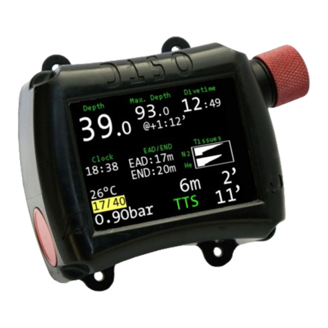
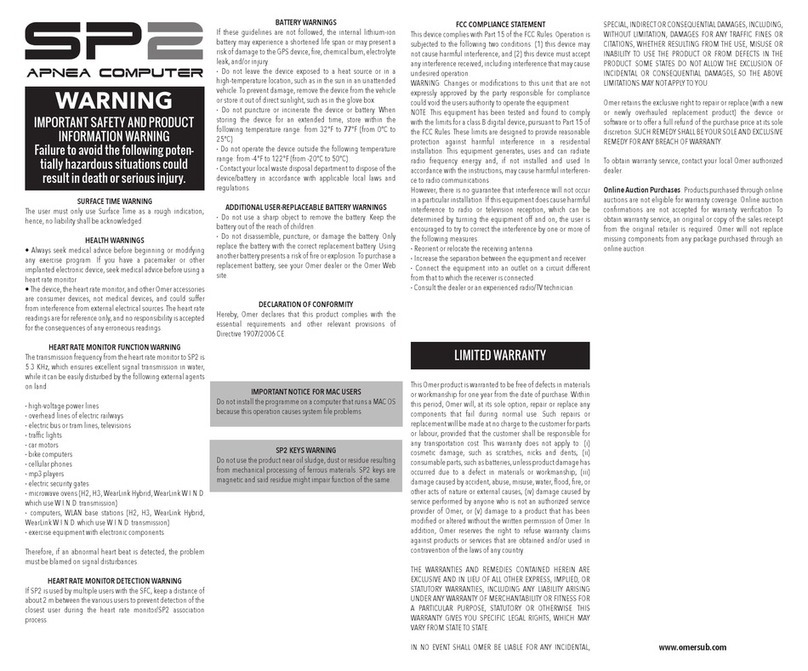
Omer SP2 instructions

Omer

Omer SP2 instructions

Dräger PAS AirPack 1 Instructions for use

Dräger

Dräger PAS AirPack 1 Instructions for use

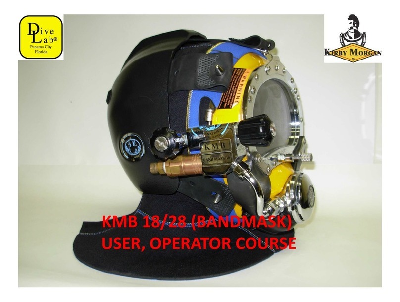
Dive Lab KIRBY MORGAN KMB 18 USER, OPERATOR COURSE

Dive Lab

Dive Lab KIRBY MORGAN KMB 18 USER, OPERATOR COURSE

Ratio Computers iDive user manual

Ratio Computers

Ratio Computers iDive user manual

CFA MSA G1 Reference manual

CFA

CFA MSA G1 Reference manual

Tusa Q 1203 CE Start guide

Tusa

Tusa Q 1203 CE Start guide

Sherwood Scuba Insight Manual guide

Sherwood Scuba

Sherwood Scuba Insight Manual guide

TREND GAUGE/60 manual

TREND

TREND GAUGE/60 manual

Tusa B.C.J. owner's manual

Tusa

Tusa B.C.J. owner's manual

Dräger Panorama Nova Dive Instructions for use

Dräger

Dräger Panorama Nova Dive Instructions for use

heinrichs weikamp OSTC 2 user manual

heinrichs weikamp

heinrichs weikamp OSTC 2 user manual

Genesis Centauri manual

Genesis

Genesis Centauri manual

manuals.online logo
manuals.online logoBrands
  • About & Mission
  • Contact us
  • Privacy Policy
  • Terms and Conditions

Copyright 2025 Manuals.Online. All Rights Reserved.

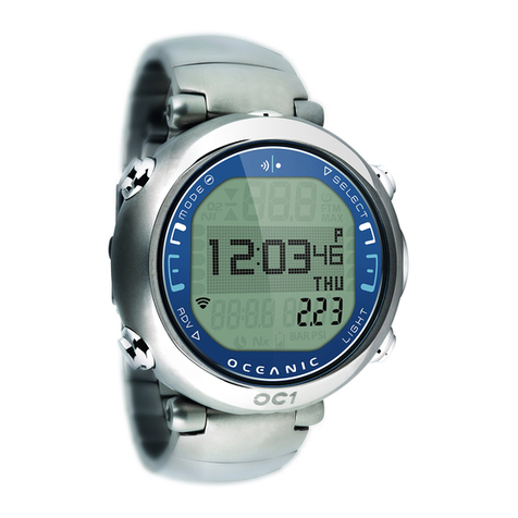
VT Pro
dive computer
operating manual
OCEANIC®
2
VT PRO
Components:
a. LED Warning Light
b. Advance (front) Button
c. Smartg o Sensing Port
d. Air Time Remaining Bar Graph
e. Se ect (side) Button
f. Icon - Operating Mode
g. Icon - Time
h. Variab e Ascent Rate Indicator
i. Graphic - Depth
j. Graphic - Demo Mode
k. Icon - Descend Arrow
Icon - Decompression Cei ing
Icon - Ascend Arrow
. Icon - Log Mode
m. Tissue Loading Bar Graph
n. Icon - A arm (Set Mode)
o. Icon - Temperature
p. Battery Indicator
q. O2 (oxygen) Bar Graph
r. Graphic - Transmitter Link
a
b
c
d
e
f
g
h
i
jk
l
m
q
r
p
n
o
r
3
CONTENTS
LIMITED TWO-YEAR WARRANTY ............................................................................................................................. 7
NOTICES ..................................................................................................................................................................... 7
DECOMPRESSION MODEL ....................................................................................................................................... 7
FCC COMPLIANCE ..................................................................................................................................................... 8
FEATURES AND DISPLAYS ............................................................................................. 9
INTERACTIVE CONTROL CONSOLE ...................................................................................................................... 10
BAR GRAPHS ........................................................................................................................................................... 11
Tissue Loading Bar Graph (TLBG) ....................................................................................................................... 11
Oxygen Bar Graph (O2BG) ................................................................................................................................... 11
Variab e Ascent Rate Indicator (VARI) ................................................................................................................. 12
Air Time Remaining Bar Graph (ATRBG) ............................................................................................................. 12
DIVE TIME REMAINING ........................................................................................................................................... 13
ALPHA / NUMERIC DISPLAYS ................................................................................................................................ 13
Cy inder Pressure ................................................................................................................................................. 13
Depth Disp ays ..................................................................................................................................................... 14
Time and Date Disp ays ....................................................................................................................................... 14
Temperature Disp ay ............................................................................................................................................. 15
AUDIBLE ALARM ...................................................................................................................................................... 15
LED Warning Light ............................................................................................................................................... 15
SMARTGLO BAC LIGHT ......................................................................................................................................... 17
POWER SUPPLY ...................................................................................................................................................... 17
Low Battery Condition .......................................................................................................................................... 18
FO2 MODE ................................................................................................................................................................. 19
FO2 50% Defau t .................................................................................................................................................. 20
4
CONTENTS (continued)
SETUP AND ACTI ATION ............................................................................................... 21
PRESSURE TRANSMITTER .................................................................................................................................... 22
ACTIVATION .............................................................................................................................................................. 22
Disp ay Modu e Identification ............................................................................................................................... 24
SURFACE MODE ...................................................................................................................................................... 25
Accessing Other Modes ....................................................................................................................................... 26
SET MODES .............................................................................................................................................................. 26
ENTERING SETTINGS -SET MODE #1 ............................................................................................................... 27
ENTERING SETTINGS -SET MODE #2 ............................................................................................................... 30
PLAN AND DI E MODES ................................................................................................ 45
TRANSMITTER SIGNAL RECEPTION GUIDE ........................................................................................................ 46
POSITIONING OF THE DISPLAY MODULE ............................................................................................................ 47
LIN INTERRUPTION UNDERWATER .................................................................................................................... 47
PRE DIVE PLANNING SEQUENCE ......................................................................................................................... 48
TISSUE LOADING BAR GRAPH .............................................................................................................................. 50
OXYGEN ACCUMULATION BAR GRAPH ............................................................................................................... 50
VARIABLE ASCENT RATE INDICATOR .................................................................................................................. 51
AIR TIME REMAINING BAR GRAPH ....................................................................................................................... 51
CONTROL OF DISPLAYS ......................................................................................................................................... 52
NO DECOMPRESSION DIVE MODE ....................................................................................................................... 53
No Decompression Dive Safety Stop ................................................................................................................... 54
DECOMPRESSION DIVE MODE ............................................................................................................................. 55
VIOLATION MODES .................................................................................................................................................. 57
Conditiona Vio ation Mode .................................................................................................................................. 57
De ayed Vio ation Modes ..................................................................................................................................... 58
Immediate Vio ation Mode and Gauge Mode ...................................................................................................... 60
HIGH PO2 DIVE MODE ............................................................................................................................................. 61
HIGH OXYGEN ACCUMULATION ............................................................................................................................ 62
USER SET DIGITAL GAUGE MODE ........................................................................................................................ 63
5
CONTENTS (continued)
POST DI E MODES ........................................................................................................ 65
POST DIVE SURFACE MODE .................................................................................................................................. 66
TRANSITION PERIOD .............................................................................................................................................. 66
AFTER THE TRANSITION PERIOD (THE FIRST 2 HOURS) .................................................................................. 67
To access the Pre Dive P anning Sequence ........................................................................................................ 68
To access the Time to F y Countdown ................................................................................................................. 68
To access the Time to Desaturate Countdown .................................................................................................... 69
LOG MODE .......................................................................................................................................................... 69
AFTER THE FIRST 2 HOURS ................................................................................................................................... 72
WET CONTACTS ....................................................................................................................................................... 72
DOWNLOADING DATA TO A PC .............................................................................................................................. 73

RESET FEATURE ..................................................................................................................................................... 74
SIMULATOR (DEMO) MODE .......................................................................................... 75
GENERAL ........................................................................................................................ 83
CARE AND CLEANING ............................................................................................................................................. 84
INSPECTIONS AND SERVICE ................................................................................................................................. 84
BATTERY REPLACEMENT ...................................................................................................................................... 86
TRANSMITTER INSTALLATION ............................................................................................................................... 92
SPECIFICATIONS ..................................................................................................................................................... 93
OCEANIC WORLD WIDE .......................................................................................................................................... 99
SERVICE RECORD ................................................................................................................................................. 100
6
WARNING: Prior to diving with the T Pro, you must also read and
understand the Oceanic Dive Computer Safety and Reference
Manual.
Pay special attention to items marked
with this Warning symbol.
7
LIMITED TWO-YEAR WARRANTY
For details, refer to the Product Warranty Registration Card provided.
COPYRIGHT NOTICE
This operating manual is copyrighted, all rights are reserved. It may not, in whole or in part, be copied, photocopied,
reproduced, translated, or reduced to any electronic medium or machine readable form without prior consent in writing
from Oceanic / 2002 Design.
VT Pro Operating Manual, Doc. No. 12-2338
© 2002 Design 2002
San Leandro, Ca. USA 94577
TRADEMAR NOTICE
Oceanic, the Oceanic logo, VT Pro, the VT Pro logo, Smart Glo, OceanGlo, Graphic Diver Interface, Tissue Loading
Bar Graph, Pre Dive Planning Sequence, Variable Ascent Rate Indicator, Set Point, Control Console, Turn Gas Alarm,
and OceanLog are all registered and unregistered trademarks of Oceanic. All rights are reserved.
PATENT NOTICE
U.S. Patents have been issued, or applied for, to protect the following design features:
Dive Time Remaining (U.S. Patent no. 4,586,136), Data Sensing and Processing Device (U.S. Patent no. 4,882,678),
Air Time Remaining (U.S. Patent no. 4,586,136), and Variable Ascent Rate Indicator (U.S. Patent no. 5,156,055). User
Setable Display (U.S. Patent no. 5,845,235) is owned by Suunto Oy (Finland).
DECOMPRESSION MODEL
The programs within the VT Pro simulate the absorption of nitrogen into the body by using a mathematical model. This
model is merely a way to apply a limited set of data to a large range of experiences. The VT Pro dive computer model
is based upon the latest research and experiments in decompression theory. Still, using the VT Pro, just as using
the U.S. Navy (or other) No Decompression Tables, is no guarantee of avoiding decompression
sickness, i.e. “the bends.” Every diver’s physiology is different, and can even vary from day to day. No machine
can predict how your body will react to a particular dive profile.
8
FCC ID: MH8A
FCC Compliance:
This equipment complies with Part 15 of the FCC Rules. Operation is subject to the following 2
conditions: 1.) this equipment may not cause harmful interference, and 2.) this equipment must accept
any interference received, including interference that may cause undesired operation.
FCC Interference Statement:
This equipment has been tested and found to comply with the limits for an Intentional Radiator, a Class
B Digital Device, pursuant to Part 15 of FCC Rules, Title 47 of the Code of Federal Regulations. These
rules are designed to provide reasonable protection against harmful interference in a commercial or
residential installation. This equipment generates, uses and can radiate radio frequency energy and, if
not installed and used in accordance with the instructions, may cause harmful interference to radio
communications.
There is no guarantee that interference will not occur in a particular installation. If this equipment does
cause interference to radio or television reception, which can be determined by turning the equipment
off and on, the user is encouraged to try to correct the interference by one or more of the following
measures:
• Reorient or relocate the receiving antenna.
• Increase the separation between the equipment and receiver.
• Connect the equipment to an outlet on a circuit different from that to which the receiver is con-
nected.
• Consult the dealer or an experienced radio/TV technician.
Warning: Changes or modifications to this unit not expressly ap-
proved by Oceanic/2002 Design could void the user's authority to
operate the equipment.
9
FEATURES and DISPLAYS
WARNING: Prior to diving with the T Pro, you
must also read and understand the Oceanic Dive
Computer Safety and Reference Manual which
provides Important Warnings and Safety Recom-
mendations as well as general product information.
10
INTRODUCTION
Welcome to Oceanic and thank you for choosing the VT Pro !
It is extremely important that you read this Operating Manual in sequence and understand it
completely before attempting to use the VT Pro.
It is equally important that you read the Oceanic Dive Computer Safety and Reference
Manual (Doc. No. 12-2262) provided with your VT Pro. It contains information that you
must become familiar with prior to diving with your VT Pro.
Remember that technology is no substitute for common sense, and a dive computer only
provides the person using it with data, not the knowledge to use it.
INTERACTI E CONTROL CONSOLE
The Interactive Control Console consists of two Control Buttons
that allow you to select display options and access specific
information when you want to see it. They are also used to link
the Transmitter, enter Settings, activate the Backlight, and ac-
knowledge the Audible Alarm.
The Front button is referred to as Advance (Fig. 1a) and the
Side button as Select (Fig. 1b).
Fig. 1 - Interactive Contro
Conso e
b
a