Oceanic Vision Series User manual

Sauna & Steam
Oceanic Ltd, Pountney Street, Wolverhampton, WV2 4HX
Vision Sauna Manual
14.7.18
Wall Hung Heater Version
(Covers all models)

Sauna & Steam
Oceanic Saunas 01902 450 550 sales@oceanic-saunas.co.uk
Table of contents
1. Introduction . . . . . . . . . . . . . . . . . . . . . . . . . . . . . . . . . . . . . . . . . . . . . 3
2. Tools . . . . . . . . . . . . . . . . . . . . . . . . . . . . . . . . . . . . . . . . . . . . . . . . . .3
3. Safety . . . . . . . . . . . . . . . . . . . . . . . . . . . . . . . . . . . . . . . . . . . . . . . . .3
4. Wiring (please refer to heater manual for more detail) . . . . . . . . . . . . . . . . . .3
5. Step 1 Base . . . . . . . . . . . . . . . . . . . . . . . . . . . . . . . . . . . . . . . . . . . . . . 4
6. Back Corner Joint . . . . . . . . . . . . . . . . . . . . . . . . . . . . . . . . . . . . . . . . . .4
7. Wooden to Glass Panel Joint . . . . . . . . . . . . . . . . . . . . . . . . . . . . . . . . . . . 5
8. Front Corner (Fixing Column). . . . . . . . . . . . . . . . . . . . . . . . . . . . . . . . . . . 5
9. Glass Panels . . . . . . . . . . . . . . . . . . . . . . . . . . . . . . . . . . . . . . . . . . . . .6
10. Door Frame . . . . . . . . . . . . . . . . . . . . . . . . . . . . . . . . . . . . . . . . . . . . . . 6
11. Roof . . . . . . . . . . . . . . . . . . . . . . . . . . . . . . . . . . . . . . . . . . . . . . . . . . . 7
12. Heater Wire & Wooden Trunking. . . . . . . . . . . . . . . . . . . . . . . . . . . . . . . . . 7
13. Benches . . . . . . . . . . . . . . . . . . . . . . . . . . . . . . . . . . . . . . . . . . . . . . . . 8
14. Internal Trim (Fix in this order) . . . . . . . . . . . . . . . . . . . . . . . . . . . . . . . . . . 9
15. Bench Assembly . . . . . . . . . . . . . . . . . . . . . . . . . . . . . . . . . . . . . . . . . . . 9
16. Back Rests . . . . . . . . . . . . . . . . . . . . . . . . . . . . . . . . . . . . . . . . . . . . . . 14
16.1. Optional Back Rest LEDs . . . . . . . . . . . . . . . . . . . . . . . . . . . . . . . . . . . 15
1.1. Optional Back Rest LEDs . . . . . . . . . . . . . . . . . . . . . . . . . . . . . . . . . . . 15
17. External Trim (Fix in this order) . . . . . . . . . . . . . . . . . . . . . . . . . . . . . . . . 17
Vision Sauna Manual

Sauna & Steam
1. Introduction
Welcome to the instruction manual for the Oceanic Saunas Vision Range. This guide is meant to be used
alongside a “Part List” which has specic information for the cabin you have been supplied.
Please take time to familiorize youself with both the steps in the manual and the specic layout of benches
and panels for the cabin your are building before making a start on assembly.
We recommend that this cabin is installed by a compentent carpenter to achieve the most professional
nished product.
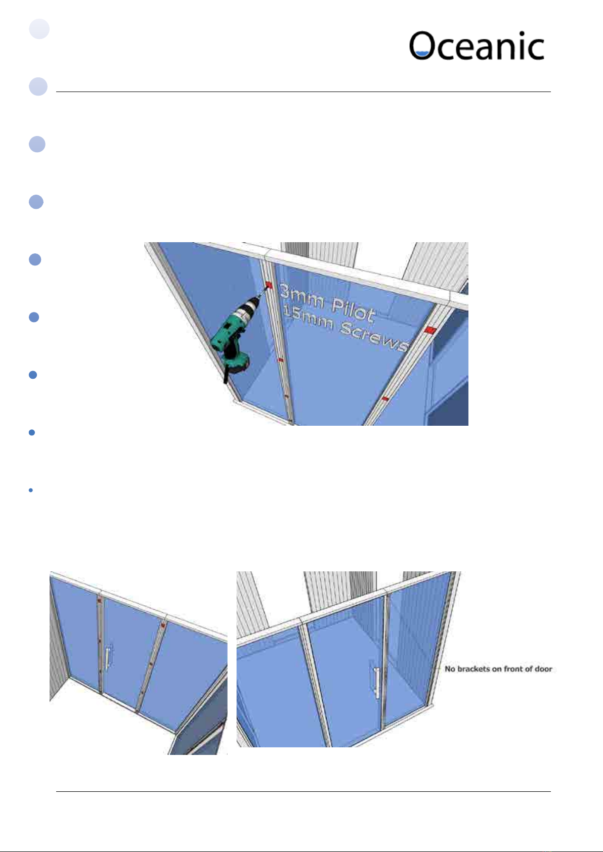
The cabin has been designed so no xtures can be easily seen, the use of a F16 or F18 brad nailer is advised
for all trim and there is some ller and sand paper supplied for nishing up the holes.
Once the cabin has been completed you may want to apply a nish, we advise to use a satin water based
varnish (do not apply inside the cabin only on the external faces).
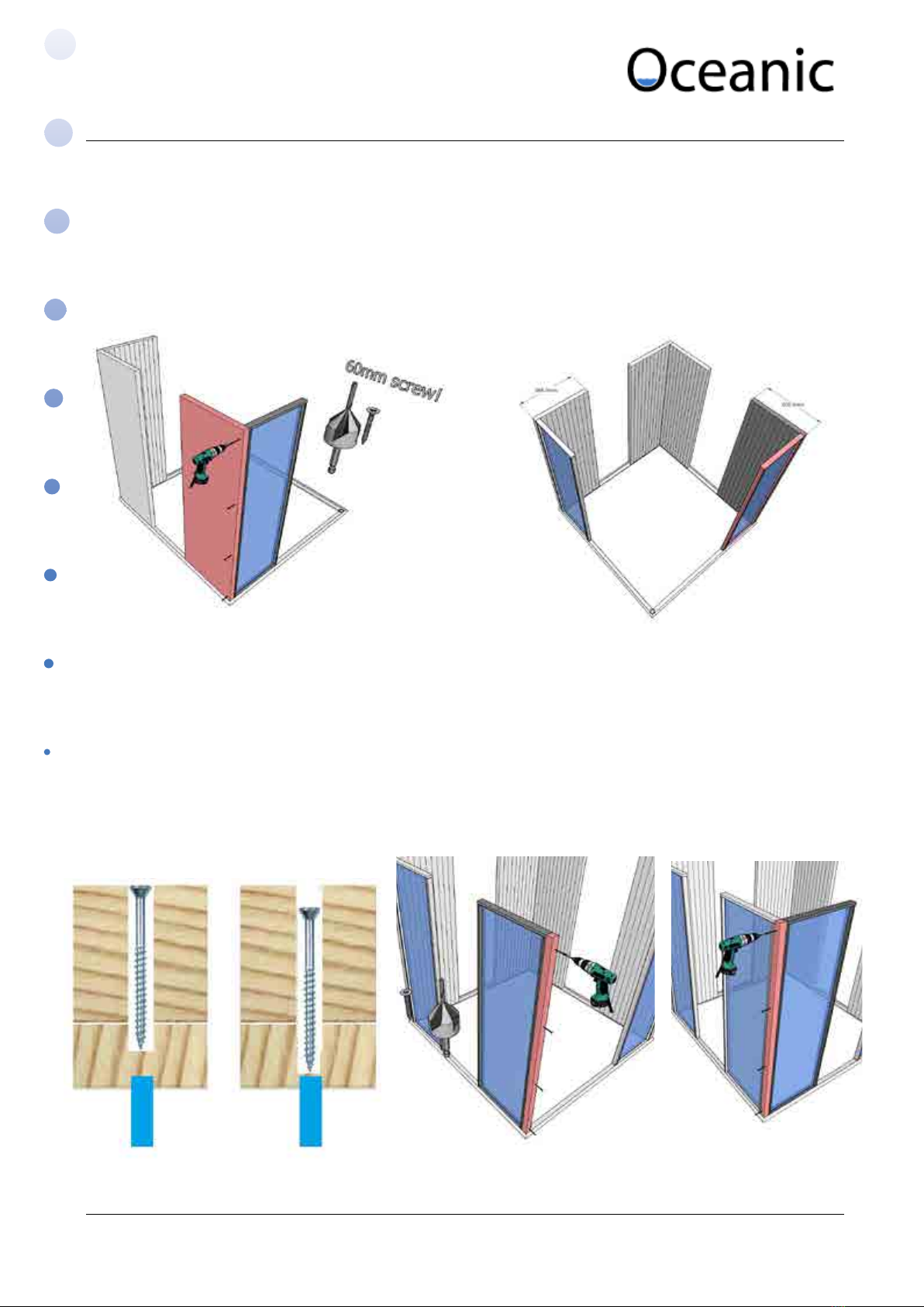
The cabin is self supporting and does not need to be xed to the ground so it is possible to assemble and
slide (with 2 or more people with care) if this is something you require to assemble into a specic area.
2. Tools
• 3 or 4mm pilot drill with countersink or separate counter sink.
• 12mm drill bit.
• Bit extension, PZ2 and PH2 screw driver bits.
• Cordless Screw Driver / Drill
• Spirit level, set square, tape measure, pencil,
• Hand saw or preferrably mitre saw.
• Brad nailer F16 or F18.
• Wood Chisel
• Filler knife or piece of plastic (e.g window packer or similar)
• Safety glasses, dust mask, safety gloves for glass, site specic PPE.
3. Safety
You must wear safety gloves and glasses at all times when handling the glass panels and door.
Please refer to the bather safety rules card supplied before turning the sauna on.
4. Wiring (please refer to heater manual for more detail)
• This sauna should be hard wired to an all pole isolator with RCD protection.
• Note any wires entering the cabin must be 150oC rated silicone. This wire is usually red in colour.
• Heater - The heater wire will either be a 3 or 5 core cable depending if you have built in controls
or separate remote controls. This wire can be hidden using trunking we supply see section 12 in
the instructions for more help.
• If you have remote controls they will rstly have a main brain which should be hidden from view,
then secondly a keypad which goes on a wall outside of the sauna and thirdly a temperature
sensor which will need to be mounted on one of the internal wall panels usually 300mm down
from the ceiling but check with the heater manual.
• Finally you will have the lighting wires, either spot lights in the ceiling or back rest LED strips.
The lighting may be powered o the remote controls if this function is available, alternatively
you can power them o a switched fuse spur.
Vision Sauna Manual

Sauna & Steam
5. Step 1 Base
i. Locate the base drawing on page 2 of the parts list for reference to dimensions.
ii. Use the 4 at brackets supplied to join each corner of the base together.
iii. Mark the holes and pilot with 3 or 4mm drill, use 4 x 15mm screws in each corner.
6. Back Corner Joint
i. The image to the right is showing the back panel in grey which is 665mm on all models.
ii. Countersink drill 4 holes evenly down the panel.
iii. Fix from the back panel into the end of the side panel using 80mm screws.
iv. The panels simply just sit onto the base, don’t x down.
Vision Sauna Manual

Sauna & Steam
7. Wooden to Glass Panel Joint
i. Similarly to how the back corner was done x 4 x 60mm screws from the back panel into the side
of the glass panel. It is very important not to tighten the screw any deeper than surface level as
the screw could reach through and hit the glass.
ii. Repeat for the other corner.
8. Front Corner (Fixing Column)
i. There is a 50x50 xing column supplied, x this to edge of the glass panel using 4 x 60mm
screws. Again do not overtighten the screws and pilot and countersink holes.
Glass Panel
Glass Frame
Column
Correct Depth Too Deep!
Vision Sauna Manual

Sauna & Steam
9. Glass Panels
i. The glass panels are xed together using at brackets in the channel as shown below.
ii. Mark all holes with pencil and use 3mm pilot drill for all holes.
iii. Position the brackets evenly but make sure they are staggered from inside and out so the screws
don’t clash. (For example inside face go 50mm down and 700mm down then externally 100mm
and 600)
iv. Fix 4 brackets on the inside and 4 on the outside join. Use 2 x 15mm screws for each bracket.
10. Door Frame
i. The door frame doesn’t have a channel on the external face so only t the brackets to the
internal join.
ii. The door must be installed opening outwards. You can hinge the door from the left or right
hinge by just rotating the frame 180 degrees.
Vision Sauna Manual

Sauna & Steam
11. Roof
i. Fix the roof panels down using 60mm
screws, countersink drill and don’t
overtighten.
ii. Start in the front or back corner then work
along xing 2 screws down into each wall
panel. All joins should be ush.
iii. Continue to add the remaining wall panels.
12. Heater Wire & Wooden Trunking
i. In some cabin layouts you may just bring the wire through one of the solid wooden panels
behind where the heater will be located. But for some of the larger models the heater is
positioned in between glass panels.
ii. We supply enough wooden trunking to go around two sides of the cabin so you will always have
enough no matter where the cable comes into the cabin from.
iii. Route the cable rst and make sure there is enough spare at the heater end for the electrician.
iv. Then measure and cut the trunking along the one or two edges that you require, if you mitre the
trunking the cable will run around the corner perfectly without any other holes or notches being
made.
Vision Sauna Manual

Sauna & Steam
13. Benches
i. Refer to your parts list for the bench layouts.
ii. For a high bench you will need to x the bench rail at 781mm from the oor and for low bench
481mm.
iii. For one tier of benches x one 640mm rail as shown to the right either at 481 or 781mm from
the oor
iv. For two tiers of benches the second rail 665 will be xed as shown.
v. Dowel plugs have been suppied to ll the holes, these are to be xed in using the ller and cut
o using a wood chisel, sanded at then lled and sanded again if required.
vi. This image shows how
the bench rails are
supported by the 50mm
double round trim and
corner mould with the
concave front. We don’t
recommend that you add
these until the cornice and
skirt is on rst. We think
this gives the best asthetic
look.
Vision Sauna Manual

Sauna & Steam
14. Heater Guard
i. Fix the guard together using 30mm screws as shown in the two below image.
ii. Hammer the dowels into the holes to cover the
screws.
iii. Chisel o the dowels, don’t chisel level
chisel about 2mm proud.
iv. Sand the dowels level.
Vision Sauna Manual

Sauna & Steam
v. Fix the guard with 4 x 30mm screws. Plug, chisel and sand.
vi. Fix two 30mm screws at the positions shown to
hang the heater.
vii. Drop the heater onto the mounting screw
then secure using 2 x 30mm screws.
Vision Sauna Manual

Sauna & Steam
15. Internal Trim (Fix in this order)
i. Cornice (convex)
(Mitre cuts if preferred)
ii. Skirt
iii. Corner Trim (concave)
iv. Overlap Mould (x over every joint between glass and wooden panels as shown)
Measure cut and x the pieces on using 25 or 35mm brads. (Optionally ll holes, then sand down when
ller is dry)
16. Bench Assembly
Important Safety Information.
The benches may have to support the body weight of several bathers. It is important that they are
correctly assembled; the holes for all screws must be predrilled to prevent the timber splitting. To
tighten the screws use a hand held screwdriver or an electrically operated one with a torque setting
that allows the screw to be fully tightened but not to spin as spinning reduces the holding power of
the screw.
Note the use of a good quality PVA adhesive (not supplied) will improve the durability of the
benches.
Maximum loadings;
Up to 1200 mm no centre support 2 x 12.5 stone people
Up to 1800 mm with 1 extra support 3 x 12.5 stones people
Before commencing the construction of the benches nd the specication sheet for the sauna you
are building. This will give detail of the correct quantities and positions of timbers and xings.
Vision Sauna Manual

Sauna & Steam
i. Screw the supporting frame together using the 4 large brackets and 20mm screws.
work bench
scrap timber
scrap timbersquare corner bench slat 19mm corner
mould spacer
ii. Lay the 5 or 6 bench slats face down on a work bench, use two pieces of scrap timber along the edges
of your bench to create a square corner to work o. Use small pieces of corner mould as 19mm spaces.
Vision Sauna Manual

Sauna & Steam
under frame 19mm corner
mould spacer
19mm corner
mould spacer
iii. Lay the supporting frame onto the slats, use spacers along the two edges to give a 19mm overhang
each side.
iv. Add the cross members, two are positioned 100mm from the ends, the third is centred, a dimension for A
can be found on your parts list.
Vision Sauna Manual

Sauna & Steam
v. Evenly space out the 14 L brackets and x using 20mm screws.
vi. Use the 30mm screws provided to x down through the cross members into the slats.
vii. If your parts list shows you have a bench leg, add this now as shown. Use 6x 40mm Screws.
Vision Sauna Manual

Sauna & Steam
viii. Screw the benches onto the wall rails using 2 x 30mm screws and 2 x 30mm washers.
ix. Fix L Benches together uising 2 x 50mm screws and 2 x 30mm washers.
Vision Sauna Manual

Sauna & Steam
17. Back Rests
i. Located the drawing in the parts list for the back rest(s).
ii. We recommend xing the back rests together from behind so there are no xings seen. You
can alternatively pin the slats onto the uprights using brad nails and ll / sand.
iii. Use 2 x 30mm screws for the top chambered slat, then use 2 x 40mm screws for the two lower
slats.
iv. Use pieces of corner mould as 19mm spacers.
v. The back rests are to be positioned 75mm from an adjacent wall. Mark with a pencil at 121mm
from the adjacent wall and 375mm up from the bench. (As there is a gap behind the bench
we recommend using a piece of wood and marking 375mm on it, then using this to mark your
xing points)
vi. For the remaining xing positioned measure between the keyways (dimension A)
vii. We recommend a height of around 250mm o the bench so 375mm for the screws will give
you this.
viii.Pilot with 3mm drill and x 30mm screrws where needed.
Vision Sauna Manual

Sauna & Steam
17.1. Back Rest LEDs
i. Find the length(s) of overlap mould with the routered channel for the LED strip to mount into.
ii. If necessary cut the piece of timber to the required length so that it can be mounted beneath
the two outermost vertical timbers on the back rest as shown above.
iii. The LED strip has male connector on one end and female connector on the other.
IMPORTANT make sure the correct end is at the correct location to be connected to the power
supply.
iv. If there are two back rests you will be supplied with 2 separate rolls of LED which can be
connected via an extension cable (also supplied). See diagram on page 19 for more details
v. Unravell the LEDs and marry the strip up along the channel, make sure you have the input end
where you will want to bring the holes through the wall.
vi. When you are happy with the length of the LED cut the strip across the incidated lines on the
stip cleanly through the copper tracks.
vii. Remove the self adhesive tape and x the LED into the wooden track.
viii.Fix the assembled LED unit to the underside of the backrest timbers using the nail gun or use a
hammer.
IMPORTANT
Check male / female connection
to power supply before installing
Routered overlap for
mounting LED strip
LED strip xed beneath the backrest
Vision Sauna Manual

Sauna & Steam
ix. To get the right position for the LED wire just mount the back rest on the wall and pencil a
point close to the connector.
x. Take the back rest o and drill a 12 mm hole for the wire.
xi. Route the wire from the roof or
control box location through the
wall.
xii. Connect up and mount the back
rest back on the wall.
Vision Sauna Manual

Sauna & Steam
Diagram 1 - Single Downlight, Single LED strip
DIagram 2 - Double Downlight, Double LED strip
DIagram 3 - Triple Downlight
12v DC
12v DC
12v transformer
12v transformer
12v transformer
12v transformer
connector block
connector block
12v downlight
12v downlight
12v downlight
12v downlight
12v downlight
12v downlight
12V extension lead connector
LED strip
LED stripMale / Female connectors
240V Mains supply
240V Mains supply
240V Mains supply
240V Mains supply
240V Mains supply
Vision Sauna Manual

Sauna & Steam
18. External Trim (Fix in this order)
i. Top facia and uprights (75mm single
round)
ii. Front corner facia (75mm double round)
iii. Internal door frame Trim
iv. Overlap (50mm double round)
v. Door trim (44mm double round)
vi. Door trim (26mm double round)
External door trim
External trim
Internal door trim
Vision Sauna Manual
Table of contents
Other Oceanic Plumbing Product manuals
Popular Plumbing Product manuals by other brands

Kohler
Kohler K-10217 Homeowner's guide

Bradley
Bradley S19-260 Installation

American Standard
American Standard Monterrey 6500 Series installation instructions

Spectrum Brands
Spectrum Brands Pfister Brea LF-042-BR Quick installation guide

Franke
Franke CMPX143 Installation and operating instructions

Peerless Faucet
Peerless Faucet P299690LF Series quick start guide