OCEM LIMS Instruction manual

Document UT-MT-0872-EN Page 1 of 37
Via della Solidariet , 2/1
40056 Valsamoggia Loc. Crespellano
BOLOGNA ITALY
Edition 08/04/2020 Supersedes edition 27/08/2019
Via della Solidariet 2/1 – 40056 Valsamoggia - Italy
THIS COPY IS NOT SIGNED SINCE IT IS FILED AND DELIVERED BY MEANS OF THE AUTOMATIC KNOWLEDGE MANAGEMENT SYSTEM (IT CAN BE SIGNED ON REQUEST). THIS DOCUMENT AND THE DATA CONTAINED HERE IN, IS
PROPRIETARY PROPERTY AND SHALL NOT BE DUPLICATED, USED OR DISCLOSED – IN WHOLE OR IN PART – FOR ANY PURPOSE WITHOUT WRITTEN CONSENT OF OCEM.
LED LUMINOUS GUIDANCE SIGN
LIMS
INSTRUCTION MANUAL FOR USE, INSTALLATION
AND MAINTENANCE
Compiled by: P. Corinto Approved by: M. Mazzotti
V. Rossi

Document UT-MT-0872-EN Page 2 of 37
Edition 08/04/2020 LIMS INSTRUCTION MANUAL
INDEX
INDEX ................................................................................................................................................. 2
INDEX OF FIGURES ............................................................................................................................. 3
INDEX OF TABLES ............................................................................................................................... 3
1 GENERAL ......................................................................................................................... 5
2 CLASSIFICATION OF SIGNS ............................................................................................... 5
2.1 Type ................................................................................................................................ 5
2.2 Legend Sizes ................................................................................................................... 5
3 MAIN FEATURES ............................................................................................................. 6
3.1 Signs Description ............................................................................................................ 6
3.1.1 Frame .................................................................................................................... 6
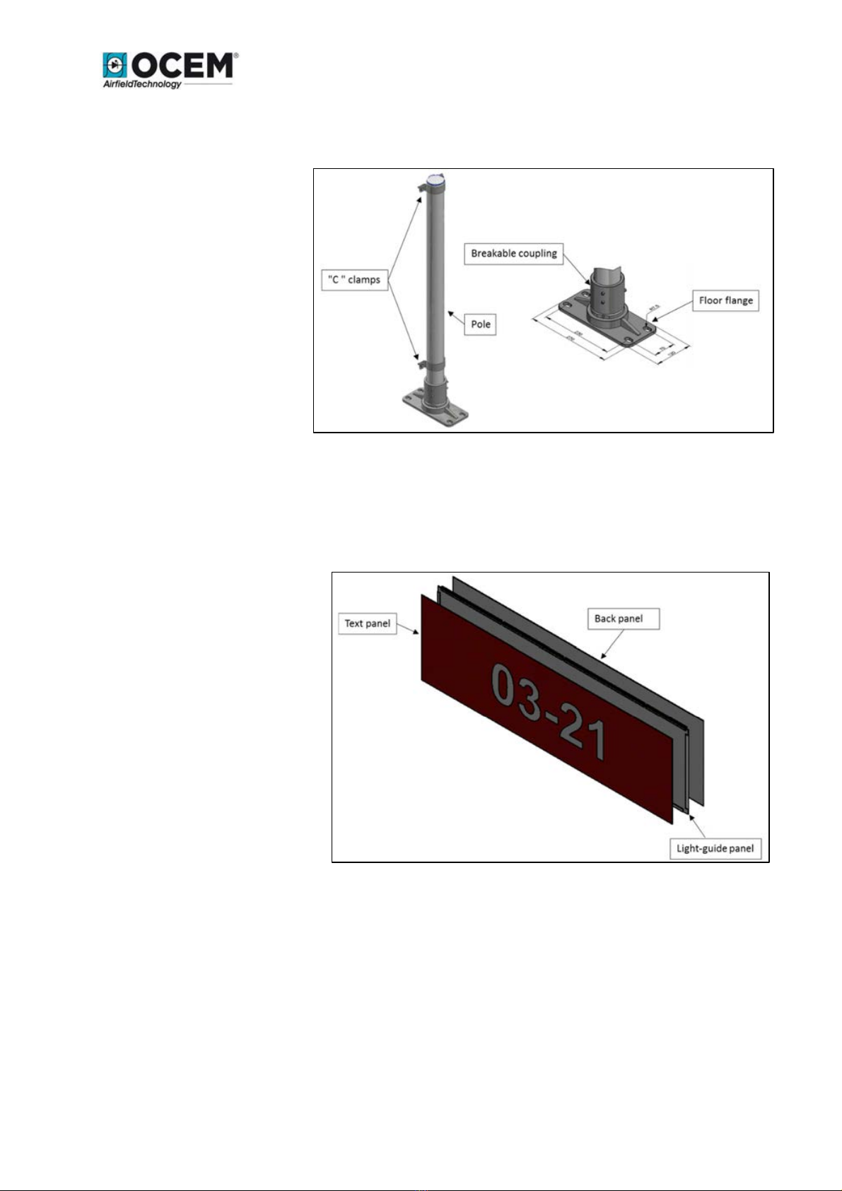
3.1.2 Supports ................................................................................................................ 7
3.1.3 Panels .................................................................................................................... 7
3.1.4 LEDs Luminous Source .......................................................................................... 8
3.1.5 Electrical circuit ..................................................................................................... 8
3.1.6 Protection earthing ............................................................................................. 10
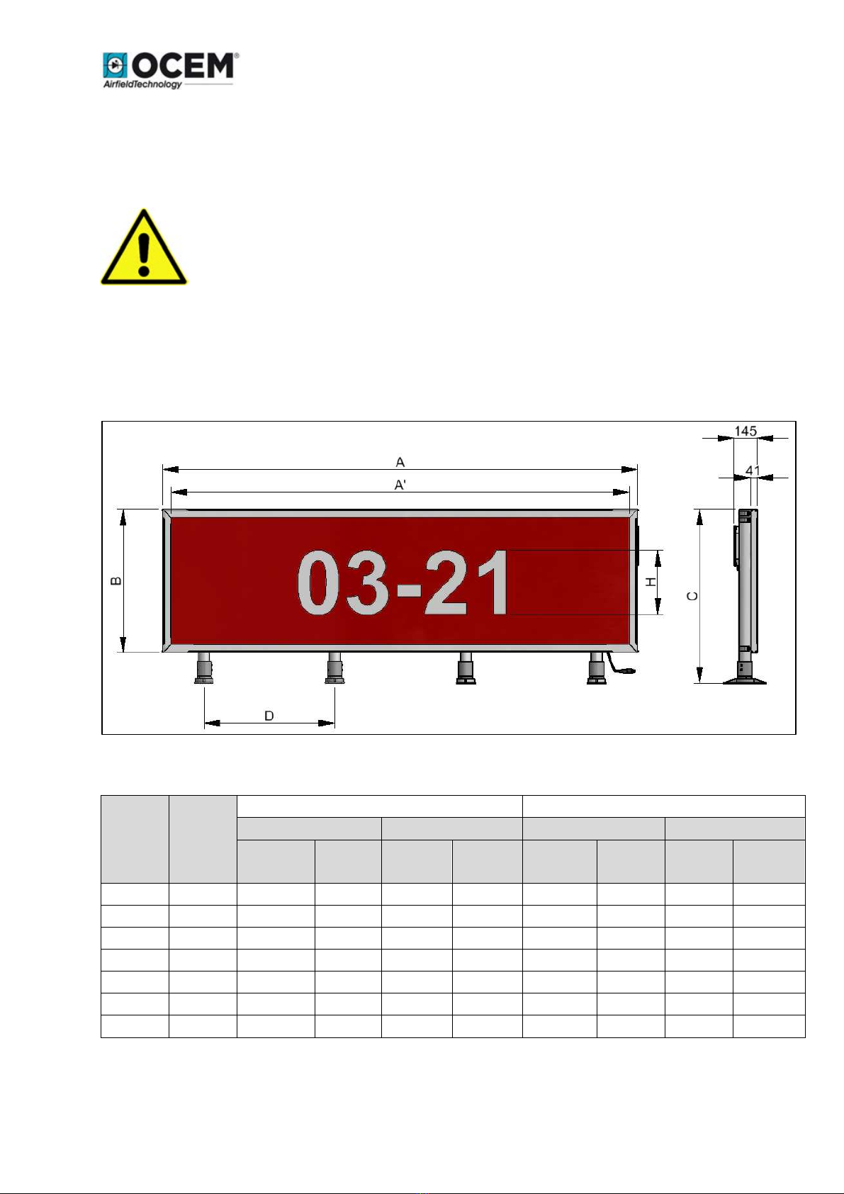
3.1.7 Models ................................................................................................................ 10
3.1.8 Monitoring Option .............................................................................................. 11
3.2 Part Number Identification .......................................................................................... 12
3.3 Environmental data ...................................................................................................... 12
3.4 Electrical Data ............................................................................................................... 13
3.5 Luminance Data ............................................................................................................ 14
4 INSTALLATION .............................................................................................................. 15
4.1 Option 70 Bird Spikes ................................................................................................... 18
5 MAINTENANCE ............................................................................................................. 19
5.1 Periodical Checks .......................................................................................................... 19
5.2 LEDs Luminous Source Replacement ........................................................................... 19
5.3 Electronic Card Replacement ....................................................................................... 23
5.3.1 Series Circuit Signs .............................................................................................. 23
5.3.2 Parallel Circuit Signs ............................................................................................ 25
5.4 Front Panel Replacement ............................................................................................. 28
5.5 Electronic Equipment Replacement ............................................................................. 31
5.6 Troubleshooting ........................................................................................................... 32
5.6.1 Series Signs .......................................................................................................... 32
5.6.2 Parallel Signs ....................................................................................................... 32
6 DRAWINGS ................................................................................................................... 33
6.1 Wiring diagram series signs .......................................................................................... 33
6.2 Wiring diagram parallel signs ....................................................................................... 35
7 LIST OF RECOMMENDED SPARE PARTS .......................................................................... 36
8 ACCESSORIES ................................................................................................................ 37

Document UT-MT-0872-EN Page 3 of 37
Edition 08/04/2020 LIMS INSTRUCTION MANUAL
INDEX OF FIGURES
Figure 1: Exploded view .................................................................................................................... 6
Figure 2: Frame.................................................................................................................................. 6
Figure 3: Support ............................................................................................................................... 7
Figure 4: Panels ................................................................................................................................. 7
Figure 5: LEDs luminous source......................................................................................................... 8
Figure 6: Electronic board ................................................................................................................. 8
Figure 7: Overall dimensions ........................................................................................................... 10
Figure 8: Electromechanical relay ................................................................................................... 11
Figure 10: Side by side installation (up), front back installation (down) ........................................ 16
Figure 11: Foundation ..................................................................................................................... 17
Figure 12: Wiring diagram (series sign without circuit stabilizer)................................................... 33
Figure 13: Wiring diagram (series sign with circuit stabilizer) ........................................................ 34
Figure 14: Wiring diagram (parallel signs powered at 110-230 VAC) ............................................. 35
INDEX OF TABLES
Table 1: Types of signs....................................................................................................................... 5
Table 2: Legend Sizes ......................................................................................................................... 5
Table 3: Signs dimensions ............................................................................................................... 10
Table 4: Sign-strip length combination ........................................................................................... 11
Table 5: Environmental Data ........................................................................................................... 12
Table 6: Power consumption at maximum luminance for series and parallel powered signs. ...... 13
Table 7: Isolating Transformer Size [Watt] without Circuit Stabilizer............................................. 13
Table 8: Isolating Transformer Size [Watt] with Circuit Stabilizer .................................................. 14
Table 9: Typical Photometric Performance ..................................................................................... 14
Table 10: Foundation sizes .............................................................................................................. 17
EDITIONS
er.
Date Description Authors Reviewers Approver
1.0 20/01/2017 FIRST ISSUE P. CORINTO E. RAULI M. MAZZOTTI
2.0 30/04/2018 GENERAL UPDATES P. CORINTO/V. ROSSI E. RAULI M. MAZZOTTI
3.0 27/09/2018 UPDATE SPARE PARTS M.BACCIGLIERI E. RAULI M.MAZZOTTI
4.0 10/01/2019 GENERAL UPDATES M.BACCIGLIERI P. CORINTO M.MAZZOTTI
5.0 27/08/2019 GENERAL UPDATES P. CORINTO M.BACCIGLIERI M.MAZZOTTI
6.0 08/04/2020 UPDATE SIGN D2 SECTION
AND GENERAL UPDATES
K.VELIU/P. CORINTO M.BACCIGLIERI M.MAZZOTTI

Document UT-MT-0872-EN Page 4 of 37
Edition 08/04/2020 LIMS INSTRUCTION MANUAL
LIST OF ATTACHMENT
Reference n° Document Code Description
ABBRE IATIONS AND TERMS
Term or abbreviation Description
LED Light Emitting Diode
ICAO International Civil Aviation Organization
EASA European Aviation Safety Agency
CCR Constant Current Regulator
FAA Federal Aviation Administration

Document UT-MT-0872-EN Page 5 of 37
Edition 08/04/2020 LIMS INSTRUCTION MANUAL
1GENERAL
The internally LEDs illuminated LIMS signs are designed to be used on airport taxiways and runways
to convey a mandatory instruction, information on a specific location or destination on a
movement area or to provide other information to meet the requirements of Surface Movement
Guidance.
LIMS are single face signs in compliance with ICAO - Annex 14 Vol.1, EASA CS-ADR-DSN Chapter N
and NATO-STANAG 3316. White on Red, Yellow on Black and Black on Yellow colour combination
may be ordered with any desired message.
The signs described in this manual are manufactured to be used on airport series circuits, through
isolating transformers, powered by 5-step (2.8 A - 6.6 A), 3-step (4.8 A - 6.6 A), and 1-step (6.6 A)
Constant Current Regulators.
The signs can be powered also by a parallel circuit voltage range 110-240 VAC, 50/60 Hz .
Consult ICAO Specs - Annex 14 and ICAO Aerodrome Design Manual - Part 4 for sign features and
use.
2CLASSIFICATION OF SIGNS
2.1 Type
Mandatory signs White legend on Red background
Location signs Yellow legend on Black background
Information (direction, destination,
boundary) sign Black legend on Yellow background
Table 1: Types of signs
A sign may consist of multiple arrays of the above messages.
2.2 Legend Sizes
Height of large legend 400 mm
Height of mid legend 300 mm
Table 2: Legend Sizes

Document UT-MT-0872-EN Page 6 of 37
Edition 08/04/2020 LIMS INSTRUCTION MANUAL
3MAIN FEATURES
3.1 Signs Description
The signs practically include the following sections (Figure 1):
A. Frame
B. Supports
C. Panels
D. LEDs luminous source
E.Electronic board
3.1.1 Frame
The frame principally consists of a bearing
bottom structure, two sides and one top
cover (Figure 2).
Bottom structure, sides and top cover are
made of extruded aluminium profiles,
realized according to our design.
The signs are equipped with a single top
cover, locked to the main structure by means
of four hexagonal knob. The main structure is
white outside painted (other colours are
available on request).
Figure 1: Exploded view
Figure 2: Frame

Document UT-MT-0872-EN Page 7 of 37
Edition 08/04/2020 LIMS INSTRUCTION MANUAL
3.1.2 Supports
Each support includes a pole,
a BREAKABLE COUPLING KIT
and a floor flange (Figure 3).
All components are made of
aluminium. The supports are
fixed to the structure with
“C” clamps.
3.1.3 Panels
The panels enclosed in the frame are (Figure 4):
•Text panel
•Light-guide panel
•Back panel
The text panel is made of
polycarbonate 4 mm thick.
The light-guide panel is made of
methacrylate, while the back
panel is made of a composite
material.
The legend is obtained by
means of adhesive coloured
translucent films applied to the
internal side of the text panel.
Figure 3: Support
Figure : Panels

Document UT-MT-0872-EN Page 8 of 37
Edition 08/04/2020 LIMS INSTRUCTION MANUAL
3.1.4 LEDs Luminous Source
The signs are illuminated by strips LEDs
(Figure 5) inserted in suitable supports.
High efficiency white LEDs are used, with
an average life of 60.000 hours.
The positioning of the LEDs has been
determined through photometric tests in
order to meet the luminance values as
required by ICAO Specs - Annex 14.
Three different strips lengths are used
(720, 960 and 1200 mm) for the different
signs lengths (see Table 4).
3.1.5 Electrical circuit
Constant Current supply (AGL Series Circuit)
Signs for constant current series circuits are equipped with an
electronic current converter housed inside a water proof
aluminium box, mounted on a side of the external frame.
About the luminance levels, two versions are available:
-1 luminance level over the whole input current range 2.8
A ÷ 6.6 A;
-2 luminance levels depending on the input current
value: in the standard version the current threshold at
which the luminance level changes is 5.9 A (but
optionally this threshold is customizable).
An option in available to monitor the light sources status,
compliant with the fail open operation (see 3.1.8).
Further, to facilitate the feeding of the sign with different
topologies of CCR, an optional stabilization circuit is available,
composed by an inductor and a capacitor (see Figure 12Figure
12: Wiring diagram (series sign with circuit stabilizer).
For the electrical connection to the isolating transformer the sign is equipped with a two-pole
cable lead with L-823 plug, style 1, protected by a corrugated pipe.
The sign is also equipped by an external disconnecting switch (main switch), which allows to light
off the sign and at the same time short circuit the isolating transformer. The main switch permits
to light off the sign without disconnecting it from the series circuit.
Figure 5: LEDs luminous source
Figure 6: Electronic board

Document UT-MT-0872-EN Page 9 of 37
Edition 08/04/2020 LIMS INSTRUCTION MANUAL
The main switch MUST BE OPERATED ONLY WITH THE CCR OFF.
In general the CCR must be turned off before any intervention on the sign.
See Figure 11 and Figure 12 for the two types of wiring diagram of the signs (without and with
stabilization circuit).
Parallel circuit voltage supply (110 -240 VAC, 50/60 Hz) (OPTION)
An option is available that permits to fed the sign through a parallel circuit voltage supply 110-
240VAC, 50/60 Hz.
In this case the luminance level is constant and the monitoring of the sign status is not available.
For the electrical connection to the AGL circuit, the sign is equipped with a three-pole cable lead
with L-823 plug, class B.
CAUTION: The three-pole plug are interconnectable with receptacle connector, take necessary
measures to avoid dangerous connection.
Wiring: Please refer to the table below and see Figure 13 for correct wiring of the sign powered at
230VAC.
(a)Connect the PE wire (green/yellow) of the sign to PE (green or green/yellow) of the power
supply network.
(b)Connect the L wire (brown) of the sign to Live (black, brown or red) of the power supply
network.
(c)Connect the N wire (blue) of the sign to Neutral (white or blue) of the circuit supply.
The sign is also equipped by an external disconnecting switch (main switch), which allows to light
off the sign.
Wire Name Europe USA
L LIVE/HOT Brown Black or Red
N NEUTRAL Blue White
PE PROTECTIVE
EARTH/GROUND
Green/Yellow
striped
Green or
Green/Yellow
striped

Document UT-MT-0872-EN Page 10 of 37
Edition 08/04/2020 LIMS INSTRUCTION MANUAL
3.1.6 Protection earthing
On the aluminium box containing the electronics, an earthing stud is available (see Figure 6).
FOR SAFETY PURPOSES, A CABLE OF 4 MM2 MINIMUM SECTION, CONNECTED TO
THE EARTHING SYSTEM OF THE AGL CIRCUIT MUST BE CONNECTED TO THE
EARTHING STUD OF THE SIGN.
3.1.7 Models
The main sign dimensions are depicted in Figure 7. The possible values for the lengths A, A’, B, C,
D and H are indicated in Table 3.
Figure 7: Overall dimensions
Length A
[mm]
isible
length
A’ [mm]
H=300mm B=704mm C=900mm H=400mm B=904mm C=1100mm
Wind @ 322 km/h Wind @ 480 km/h Wind @ 322 km/h Wind @ 480 km/h
Supports
quantity
Distance
D [mm]
Supports
quantity
Distance
D [mm]
Supports
quantity
Distance
D [mm]
Supports
quantity
Distance
D [mm]
1094
990
2
580
2
580
2
580
2
580
1354
1250
2
840
2
840
2
840
3
420
1574
1470
2
1060
2
1060
2
1060
3
530
2054
1950
3
770
3
770
3
770
4
513
2294
2190
4
593
4
593
4
593
4
593
2534
2430
4
673
4
673
4
673
6
404
2994
2890
4
827
4
827
4
827
6
496
Table 3: Signs dimensions

Document UT-MT-0872-EN Page 11 of 37
Edition 08/04/2020 LIMS INSTRUCTION MANUAL
Three different LED strips are possibly mounted on the signs, according to the overall sign lengths.
The correspondence between sign length and LED strip length are showed in Table 4:
Sign length A
[mm]
Strip LEDs
Quantity
Length [mm]
1094
1
960
1354
1
1200
1574
2
720
2054
2
960
2294
3
720
2534
2
1200
2994
3
960
Table : Sign-strip length combination
3.1.8 Monitoring Option
Note: Option available only for Signs powered by a constant current series circuits.
The electronic card of the signs with Monitoring Option has an electromechanical relay with a
normally closed contact. This contact is assembled in series with the feeding circuit of the
electronic card.
When one or more LED strips fail, the normally closed contact opens, turning off the electronic
board and the sign lights off.
A manual intervention is needed to restore the relay contact in closed position and then to permit
the sign to switch on again.
Note: If the relay contact is restored after a LED strip
failure and no replacement is performed, the monitoring
functionality is automatically disabled. The monitoring will
not be reactivated by the system until the failed LED strips
will be replaced with good strips.
The Figure 8 shows the positions of the relay contact.
Figure 8: Electromechanical relay
FAULT
NO
FAULT
FAULT
NO
FAULT

Document UT-MT-0872-EN Page 12 of 37
Edition 08/04/2020 LIMS INSTRUCTION MANUAL
3.2 Part Number Identification
LIMS01 – 3 – 20 – 1 – 01
Basic Part Number:
ersion:
Message Size:
3 = Sign, 300 mm Legend Height
4 = Sign, 400 mm Legend Height
Type (visible length mm):
10 = 990 20 = 1950 30 = 2890
13 = 1250 22 = 2190
15 = 1470 24 = 2430
Luminance Level:
1 = Constant Luminance
2 = Two Luminance Levels
Options:
D2 = Parallel circuit voltage 110-240 VAC, 50/60 Hz
01 = Tether (2 tethers for signs with number of supports ≥ 3)
02 = Yellow frame (Special Version)
03 = Black frame (Special Version)
04 = Circuit Stabilizer
10 = Monitoring
48 = Reinforced version FAA-mode 3 (480 km/h)
69 = Orange rear side for single face signs (Italy)
70 = Bird Spikes
3.3 Environmental data
Temperature -40°C to +55°C
Weather All outdoor conditions, exposure to: driving rains, snow and icing, salt-
laden atmospheres, relative humidity from 5 % to 95 %.
Wind Speed 322 Km/h (standard version) or 480 km/h (reinforced version – OPTION
48) ICAO Aerodrome Design Manual Part 6 Frangibility
Table 5: Environmental Data

Document UT-MT-0872-EN Page 13 of 37
Edition 08/04/2020 LIMS INSTRUCTION MANUAL
3.4 Electrical Data
The luminous signs are powered by series circuits through isolating transformers compliant to FAA
Specs FAA L830-L831 or through a parallel circuit voltage (110-240VAC). The power consumption
of the LIMS signs is reported in Table 6. The power factor for the sign is:
•higher than 0.8 for all type of signs fed by parallel circuit voltage 110-240VAC;
•higher than 0.9 for all type of signs without Circuit Stabilizer1 fed by series circuit.
Type
Power Consumption
Series circuit [W]
Power Consumption
Parallel circuit [W]
10
32
15
13
36
17
15
40
22
20
51
30
22
53
33
24
61
34
30
70
43
Table 6: Power consumption at maximum luminance for series and parallel powered signs.
The minimum size of the isolating transformer depends on both the sign type and the selected
power supply (i.e. the number of current steps provided by the CCR), according to Table 7 and
Table 8.
Type CCR TYPE
CCR 5 STEP
(2.8 A-6.6 A)
CCR 3 STEP
(4.8 A-6.6)
CCR 1 STEP
(6.6 A)
Constant
Luminance
Two
Luminance
Levels
Constant
Luminance
Two
Luminance
Levels
Constant
Luminance
10
SINUSOIDAL
150
65*
65*
65*
65*
PHASE CUT
150
100
100
65*
65*
13 SINUSOIDAL 150 100 100 65* 65*
PHASE CUT 150* 100 100* 100 100
15
SINUSOIDAL
150
100
100
100
65*
PHASE CUT
200
100*
100*
100
100
20
SINUSOIDAL
200
100
100*
100
100
PHASE CUT
200*
100*
150
100*
100*
22
SINUSOIDAL
200
100
150
100
100
PHASE CUT
200*
100*
150
100*
100*
24
SINUSOIDAL
200*
100*
150
100*
100*
PHASE CUT
300
150
150*
150
150
30
SINUSOIDAL
300
150
150
150
150
PHASE CUT
300
150
200
150
150
(*) we suggest to select a larger transformer size in case individual monitoring is performed with MCC devices
Table 7: Isolating Transformer Size [Watt] without Circuit Stabilizer
1 Power factor with Circuit Stabilizer drops down to 0.5, for further information contact Energy Technology OCEM.

Document UT-MT-0872-EN Page 14 of 37
Edition 08/04/2020 LIMS INSTRUCTION MANUAL
Type CCR Type
CCR 5 STEP
(2.8 A-6.6 A)
CCR 3 STEP
(4.8 A-6.6)
CCR 1 STEP
(6.6 A)
Constant
Luminance
Two
Luminance
Levels
Constant
Luminance
Two
Luminance
Levels
Constant
Luminance
10
SINUSOIDAL
150
100
*
100
*
100
*
100
*
PHASE CUT
150
*
150
150
150
150
13
SINUSOIDAL
150
150
150
150
150
PHASE CUT
200
150
150
150
150
15
SINUSOIDAL
150
*
150
150
150
150
PHASE CUT
200
150
150
150
150
20
SINUSOIDAL
200
150
150
150
150
PHASE CUT
300
150
*
150
*
150
*
150
*
22
SINUSOIDAL
300
200
200
200
200
PHASE CUT
300
300
300
300
300
24
SINUSOIDAL
300
200
200
200
200
PHASE CUT
300
300
300
300
300
30
SINUSOIDAL
300
200
*
200
*
200
*
200
*
PHASE CUT
300
300
300
300
300
(*) we suggest to select a larger transformer size in case individual monitoring is performed with MCC devices
Table 8: Isolating Transformer Size [Watt] with Circuit Stabilizer
3.5 Luminance Data
Two versions of LIMS signs are available, according to the luminance option selected.
One luminance level sign: available for both the power supply configurations. The luminance is
constant for any value of the series circuit current from 2.8A to 6.6A and the relevant values are
shown in Table 9.
Two luminance level sign: available only for signs powered by a series circuit. The high intensity
level is selected with a current greater than 6A, while with any values between 2.8A and 6A the
low intensity luminance is provided. The high and low luminance levels are reported in Table 9.
High Intensity Level
(and Constant Luminance) Low Intensity Level
ICAO
Requirements
Typical
Value
ICAO
Requirements
Typical
Value
Average luminance yellow >150 cd/m
2
180 cd >50 cd/m
2
110
Average luminance red >30 cd/m
2
40 cd >10 cd/m
2
16
Average luminance white >300 cd/m
2
350 cd >100 cd/m
2
135
Maximum ratio between
two adjacent points <1.5 1.3 <1.5 1.3
Maximum ratio across sign <5.0 1.8 <5.0 1.8
Table 9: Typical Photometric Performance

Document UT-MT-0872-EN Page 15 of 37
Edition 08/04/2020 LIMS INSTRUCTION MANUAL
NOTE: for signs powered by a series circuit, the electrical and luminous data are referred
to constant current regulators and isolating transformers manufactured and/or distributed
by OCEM. The data may change with constant current regulators and/or transformers
manufactured by other Companies.
4INSTALLATION
a) Take as reference Table 3 for spacing between breakable couplings.
b) Remove the sign from the relevant packing.
c) The signs are normally installed so that the cable entry is located toward the runway or taxiway
edge.
d) The concrete foundation for the sign should be flat and levelled. Refer to Figure 10 for relevant
data. The isolating transformer must be placed inside a concrete pit complete with pipe elbow
for the secondary cable passage or inside a steel base complete.
e) It is recommended that the M12 anchor bolts used for the flange anchoring, are mounted after
the completion of the concrete foundation. The anchor bolts must be walled accurately to
assure the parallelism of the centreline marked on the flange and the sign centreline.
f) Remove the frangible couplings/floor flanges from the bottom of the sign by loosening the
locking screws (set screw M8x14).
g) Taking care of the levelling of the floor flanges is very important to ease the installation of the
sign. Place a long carpenter level across the top of the breakable couplings to verify their
alignment and levelling. Do not tighten the flanges anchor nuts, tight (only finger-tight) until
the sign installation is complete.
Lower the sign with the legs onto the frangible couplings and tight the locking screws. Check
the sign to be sure that it is levelled. Shim the floor flanges as required and put drying grout
under the flange if necessary.
NOTE: some vertical adjustment can be obtained by rotating the frangible couplings a turn or two
in the floor flanges.
h) Once the sign has been levelled, tighten the anchor nuts securely. (NOTE: anchor hardware is
not supplied with the sign). Anchor hardware should be corrosion resistant.
i) Connect the cable plug of the sign to the socket of the isolating transformer. The plug-socket
connection should be secured depending upon the installation method.

Document UT-MT-0872-EN Page 16 of 37
Edition 08/04/2020 LIMS INSTRUCTION MANUAL
j) CONNECT THE EARTHING STUD OF THE SIGN TO THE EARTHING SYSTEM OF THE AGL CIRCUIT
THROUGH A CABLE OF AT LEAST 4 MM2.
THE CONNECTION OF THE SIGN EARTHING STUD TO THE AGL EARTHING SYSTEM
IS MANDATORY FOR SAFETY PURPOSES.
k) After the signs have been installed, turn the circuit on to the lowest step and check to see that
all the signs are lighted.
Figure 9: Side by side installation (up), front back installation (down)

Document UT-MT-0872-EN Page 17 of 37
Edition 08/04/2020 LIMS INSTRUCTION MANUAL
Figure 10: Foundation
Type
T [mm]
10
3469
13
3729
15
3949
20
4429
22
4669
24
4909
30
5369
Table 10: Foundation sizes

Document UT-MT-0872-EN Page 18 of 37
Edition 08/04/2020 LIMS INSTRUCTION MANUAL
4.1 Option 70 Bird Spikes
a) Remove the device from the packaging and clean the back of the device.
b) Remove the film from the double-sided adhesive
tape.
c) Apply the device on the double-sided adhesive by
pressing hard.
-The 160mm detail must be applied to the
Electronic Box.
-The other details on the table profile
160mm

Document UT-MT-0872-EN Page 19 of 37
Edition 08/04/2020 LIMS INSTRUCTION MANUAL
5MAINTENANCE
ATTENTION!
The power supply or CCR
MUST be TURNED OFF before any intervention on the sign.
5.1 Periodical Checks
Daily Check for burned-out led
Monthly Check for dirty panels
Semi-Annual Check for loose wire connections
Check for cracked or deteriorated wires
5.2 LEDs Luminous Source Replacement
a) Be sure that the power supply is turned OFF; in the case of series circuit, de-
activate the CCR
(CCR OFF).
In any case turn the main switch to OFF position.
b) Loosen the screws (without removing
them) of the top “C” clamps of the
supports. The number is variable based on
the poles number.
c) Remove four screws that connect the top
cover with the sides of the structure.

Document UT-MT-0872-EN Page 20 of 37
Edition 08/04/2020 LIMS INSTRUCTION MANUAL
d) Lift the top cover carefully of a few centimeters, disconnect the earth cable and remove the
top cover.
e) Remove the spiral and disconnect the connector of the damaged LEDs luminous source by
pressing on the tab indicated by the arrow.
Other manuals for LIMS
2
Table of contents
Other OCEM Digital Signage manuals