OEG 212000017 User manual

www.oeg.net
Festwertregler
Montage- und Bedienungsanleitung
D
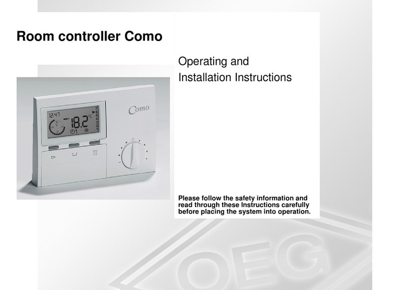
Constant temperature controller
Installation and operating instructions
GB
Régulateur à valeur constante
Notice de montage et d’utilisation
FR
Regolatore di temperatura costante
Istruzioni per il montaggio e l´uso
Vaste waarde regelaar
Montage- en bedieningshandleiding
IT
NL

22
ContentsGB Introduction
Appearance of the controller
Initial controller setup
Step -
Language selection
Step -
Hydraulic scheme selection
Step -
Opening of the mixing valve
Graphic LCD display
Description and design
of the main display
Descpription of symbols
on the display
Controler mode symbols
Temperature and other
data symbols
Symbols for notices
and warnings
Display for help,
notices and warnings
Menu entry and navigation
Menu structure
and description
.
.
.
.
.
.
.
.
.
.
.
.
.
.
.
Temperature settings
Operation mode
Manual mode
Heating or cooling operation
mode selector
Basic settings
Data overview
Controller parameter
Basic parameters
Controller parameters and
auxiliary tools
Service parameters
Factory settings
Operation mode by
sensor Failure
Controller installation
Controller’s electric
connection
Technical data
Disposal of old electrical
& electronic equipment
Hydraulic schemes
.
.
.
.
.
.
.
.
.
.
.
.
.
.
.
.
.
Constant temperature controller
GB
Introduction1.0 Controllers FWR, FWR are modern designed, microprocessor-driven devices made with
digital and SMT technology.
The controller are provided as a constant temperature controller with actuator designed
for heating applications. The most common use is to control the return temperature in the
boiler. Controller FWR besides controlling the actuator also controls the circulating
pump.
Note: For initial setup see Initial controller setup, page .

Constant temperature controller
23
Appearance of
the controller
2
GB
. Graphic display
. Clutch for manual operation.
. Button Return back.
. Button Move to left, decreasing.
. Button Menu entry, confirmation of selection.
. Button Move to right, increasing.
. Button Help.
. LED indication - valve rotation right.
. LED indication red - fault, error.
. LED indication - valve rotation left.

Constant temperature controllers are equipped with an innovative solution, which allows
initial setup of the controller in only three steps.
When you connect the controller to the power supply for the first time, the software ver-
sion is shown. Next, the first step appears on the screen.
Note: Selected hydraulic scheme can be later changed with service parameter S..
24
Initial controller setup3.0
Step -
Language selection
3.1 Using buttons and you select the required
language.
Press the button to confirm the selected
language. After selecting the language, the control-
ler requires confirmation of the selection by pres-
sing the button .
If you accidentally selected the wrong language, go
back to reset the language by pressing button .
Step -
Hydraulic scheme selection
3.2 Next, you select a hydraulic scheme for the control-
ler function. Move between schemes by means of
buttons and .
Confirm the selected scheme by pressing the
button .
After you selected the scheme, the controller requi-
res confirmation of the selection by pressing the
button .
If you accidentally selected the wrong scheme, go
back to reset the scheme by pressing button .
Note: Selected mixing valve opening direction can be later changed with service
parameter S..
Step -
Opening of the mixing valve
3.3 Press icon which indicates the proper direction of
mixing valve opening direction. Between icons you
can move with buttons and .
After you selected the correct direction, the control-
ler requires confirmation of the selection by pres-
sing the button .
If you accidentally selected the wrong mixing valve
opening direction, go back to reset the the selection
by pressing button .
Constant temperature controller
GB

25
Graphic LCD display 1.04
Description and design
of the main display
4.1
All important data of controller operation are shown on the graphic LCD display.
Display of information on the screen:
The controller mode, notifications and warnings are displayed in the upper third of the
display. For switching between basic display and display of the hydraulic scheme use the
button .
To check the temperature and other data, use buttons and . The number of sensors
and other data, which can be listed on the display, depends on the selected hydraulic
scheme and controller settings.
Note: If you would like to have a specific data display to appear after you stop using
the keyboard then select the desired data with buttons and . Confirm
the selected screen by pressing the button for seconds.
Note: When you press the button for seconds, then the display of the temperature
will change from one to two rows and vice versa. On the two line
temperature display, the measured temperature is displayed in the first row
and the required or calculated temperatire in the second row.
Controller mode. Controller mode.
Temperature, protection functions and
overview of other data.
Notifications
and warnings.
Constant temperature controller GB

26
Descpription of symbols
on the display
5.2
Controler mode symbols5.1
Temperature and other
data symbols
5.2
Symbols for notices
and warnings
5.3
Symbol Description
Heating
Cooling
Automatic mode
Stand by
Manual mode
Symbol Description
Measured temperature
Set point or calculated temperature
Supply temperature
Boiler temperature
Stand- pipe temperature
Boiler return temperature
Temperature measured by the sensor T, T
T1, T2
Symbol Description
Notifications
In case of exceeding the maximum temperature or activation of protection
function, the controller indicates the event with flashing symbol on the display.
If the maximum temperature is no longer exceeded or if the protection
function is turned off, a lited symbol indicates a recent event.
Press to open the screen to check notifications.
Warning
In the event of sensor failure, the controller indicates the failure with
flashing symbol on the display. If the issue is resolved or no longer
present, a lited symbol indicates a recent event.
Press to open the screen to check warnings.
Constant temperature controller
GB

27
By pressing the button the screen for help, messages and warnings will be oppened in
which the following icons are available.
Short manual
Short manual for use of the controller.
Controller version
Overview of controller type and software version.
Notifications
Log of exceeded maximum temperatures and activated protection functions.
By pressing the buttons and move through the list of notifications.
Press to exit the list.
Warnings
Log of sensors, pump or flow meter failures.
By pressing the buttons and move through the list of warnings.
Press to exit the list.
Delete warning and notification logs
By pressing the button will erase notification and warning log. All sensors
that are not connected will be deleted from the list of failures.
Note: Failures of sensors that are required for controller operation can not
be deleted.
Display for help,
notices and warnings
6
To enter the menu, press the button .
Move around the menu using the buttons and , with the button you confirm your
selection.
By pressing the button you return to the previous screen.
Note: If some time no button is pressed, the backlight turns off or is reduced according
to the setting.
Menu entry and
navigation
7
Constant temperature controller GB

28
Menu structure
and description
8.0
TEMPERATURE SETTINGS
OPERATION MODE
BASIC PARAMETERS
Set-point temperature
Automatic operation
Switch-off
Select Heating Cooling mode
Manual operation
Language selection
Time and date
Duration of active display illumination
and menu autoexit
DISPLAY SETTINGS
DATA OVERVIEW
CONTROLLER PARAMETERS
SERVICE PARAMETERS
FACTORY SETTINGS
Diagrams of measured temperatures by days for last week
Diagrams of measured temperatures for current day
Output operation time counter*
Special service data
Basic settings
Settings for the heating circuit*
Basic settings
Settings for the heating circuit
Settings for heat source
Reset of all controller parameters
Reset of all controller settings and restart of initial setup
Save user settings
Load user settings
* Not available
Settings for heat source*
Constant temperature controller
GB

In this menu the operating mode of the controller is selected.
Select the operaion mode with buttons , and confirm with button .
Exit the settings by pressing the button .
29
Operation mode 8.2
In the menu only the temperatures are displayed, where you can set the
set-point temperature by the selected hydraulic scheme.
By pressing buttons , and you choose the required temperature, and a new
window opens:
Set the set-point temperature with buttons , and confirm with button .
Exit the settings by pressing the button .
Temperature settings 8.1
Current value
of set-point
temperature
(numeric mode)
Graphic review
of settings
Current value of
set-point temperature
(analogue mode)
Value of the last
confirmed setting
Default value
Setting range
Automatic operation
Controller switch-off
Heating or cooling operation mode selector
Manual mode
Constant temperature controller GB

30
Manual mode8.3
Heating or cooling operation
mode selector
9.0
This mode is used for testing the system or in case
of malfunction. Every output can be manually acti-
vated
or deactivated.
Move with the buttons and between the in-
dividual outputs R, M- or M . The output, which
you want to change is selected by pressing the but-
ton .
ON, OFF or AUTO starts flashing. Now the output
can be changed using the buttons and . The
setting is confirmed by pressing the button .
Exit the setup menu with the button.
You set the exact time and date in the following
manner:
By pressing buttons and move among
individual data. By pressing button you select
data that you want to change. When data flashes,
change it by pressing buttons , and confirm
it with the button .
Exit the settings by pressing the button .
The required user language is selected by pressing buttons , and confirmed with
button . Exit settings by pressing the button .
The menu is intended for language,
time, date and display settings
Heating operation mode is active.
Cooling operation mode is active.
Basic settings10.0
Language selection
Time and date
Constant temperature controller
GB

You change settings by pressing buttons and and confirm by pressing button .
Exit the settings by pressing button .
Note: The change of settings is carried out when you confirm it by pressing button .
By pressing buttons , and you select and confirm required setting.
A new window opens:
Note:
To view the sensor-diagrams move with buttons and between the sensors.
By pressing the button the date of displayed temperature begins to
flash. Use buttons and to move between days.
Return to the temperature selection by pressing the button .
The range of the temperature display on the graph can be changed with the
the button .
Exit the diagram overview by pressing the button .
31
Data overview 11
The following settings are available:
Time of active screen illumination and autoexit from menu to the
main screen.
current setting value
Graphic
symbol
current setting
value (graphic)
current setting value
(numeric value)
The last confirmed
value of setting
factory setting
setting range
Controller parameter 12
In this menu there are icons to access the following data on controller
performance:
DIAGRAMS OF MEASURED TEMPERATURES BY DAYS FOR LAST WEEK
The graphical representation of the temperature profile in days, for each sensor.
There are records of the temperatures for the last week of operation.
DIAGRAMS OF MEASURED TEMPERATURES FOR CURRENT DAY
Detailed graphic overview of temperature in current day for each sensor.
How often are temperatures logged is set with parameter P..
OUTPUT’S OPERATION TIME COUNTERS*
Counters of controller’s outputs operation time.
SPECIAL SERVICE DATA
Intended for diagnostics for technical service.
Constant temperature controller GB
* Not available

The setting is changed by pressing the button .
The value will start blinking and can be changed with the and . The setting is
confirmed by pressing the button .
Move with buttons and to other parameters and repeat the procedure.
Exit the parameter settings by pressing the button .
Controller parameters
and auxiliary tools
12.1
32
All additional settings and adjustments of controller performance are carried out by
means of parameters. User-, Service- and parameters are found on the second menu
screen.
Basic parameters12.2 The basic parameters are listed in one group P - basic parameters.
Content of basic parameters is displayed as follows:
Parameter mark Current
parameter value
Setting range
Parameter
description
Factory default
Constant temperature controller
GB

33
Basic parameters 12.2
Basic parameters:
Para- Function Parameter description Setting Default
meter range value
P.
P.
P.
P.
P.
TEMPERATURE ROUND
UP
You set the accuracy of displayed
temperatures.
- . °C
- . °C
- . °C
- °C
AUT. SHIFT OF CLOCK
TO SUMMERWINTER
TIME
With the help of a calendar, the control-
ler carries out the automatic changeover
between summer and winter time.
- NO
- YES
TONES By setting this field you define sound
signals of the controller.
- OFF
- KEYPAD
- ERRORS
- KEYPAD
AND ERRORS
ADVANCED
TEMPERATURE
SCREEN
Advanced screen means that while
checking temperatures you can see
measured and required or calculated
temperature.
- NO
- YES
PERIOD OF TEMPERAT.
LOGGING
By setting this field you define how
often the measured temperatures
are saved.
- min
Constant temperature controller GB

The setting is changed by pressing the button . Because the parameters are factory
locked, a new screen appears. Here you have to enter the unlock code.
Service parameters12.3
34
Service parameters are arranged in groups S - Basic parameters, S - Parame-
ters for the heating circuit. With service parameters it is possible to activate or
select many additional functions and adaptations of controller performance.
When you select the required para meter group in the menu, a new screen
opens:
Parameter
mark
Parameter value
Parameter
description
Setting range
Default value
Hydraulic scheme
By pressing buttons and you mark the num-
ber which you want to modify and press the
button .
When the number flashes you can modify it by
pressing buttons , and confirm it by pressing
button .
When the correct code is inserted, the controller
unlocks the parameters for editing and returns to
the selected group of parameters.
Return back from unlocking by pressing button .
Note: Factory set code is “”.
Constant temperature controller
GB
Modify the value of the unlocked parameter by pressing buttons and . The setting
is confirmed by pressing the button . By pressing buttons , you can move to
another parameter and repeat the procedure.
exit parameter settings by pressing the button .
Warning: Change of service and functional parameters must be carried out only by
a properly qualified expert.
35
Service parameters 12.3
Basic parameters:
Para- Function Parameter description Setting Default
meter range value
S.
S.
S.
S.
S.
S.
S.
HYDRAULIC SCHEME Selection of hydraulic scheme. -
CODE FOR
UNLOCKING THE
SERVICE SETTINGS
This setting enables the change of code
which is necessary to unlock the service
settings.
WARNING! Keep new code on a safe
place. Without this code is impossible
to change service settings.
ACTUATOR
OPENING DIRECTION
Setting of actuator turning direction -
valve opening.
- RIGHT
- LEFT
ANTI-BLOCK
FUNCTION FOR
PUMP AND VALVE
All outputs that haven’t been activated
in the last week are activated on Friday
at : for seconds.
- OFF
- ON
DISPLAY ORIENTATION Setting of display orientation. - REGULAR °
- ROTATED
°
SENSOR T
CALIBRATION
Correction of displayed measured tem-
perature for sensor T.
- K
SENSOR T
CALIBRATION
Correction of displayed measured tem-
perature for sensor T.
- K
Constant temperature controller GB

36
Service parameters12.3 Parameters for mixing circuit:
Para- Function Parameter description Setting Default
meter range value
S.
S.
S.
S.
S.
S.
S.
S.
S.
S.
MIN. SETPOINT
TEMPERATURE IN
HEATING MODE
Setting of minimal allowed setpoint
temperature in heating mode. Setpoint
temperature cannot be adjusted lower
as with this parameter.
°C
°C
MAX. SETPOINT
TEMPERATURE IN
HEATING MODE
Setting of maximal allowed setpoint
temperature in heating mode. Setpoint
temperature cannot be adjusted higher
as with this parameter.
°C
°C
MIN. SETPOINT
TEMPERATURE IN
COOLING MODE
Setting of minimal allowed setpoint
temperature in cooling mode. Setpoint
temperature cannot be adjusted lower
as with this parameter.
°C
°C
MAX. SETPOINT
TEMPERATURE IN
COOLING MODE
Setting of maximal allowed setpoint
temperature in cooling mode. Setpoint
temperature cannot be adjusted higher
as with this parameter.
°C
°C
MIXING VALVE
I - CONSTANT
Setting of mixing valve control fre-
quency - how often mixing valve posi-
tion is being controlled. Smaller value
means low frequency, higher value
means higher frequency.
, ,
MIXING VALVE
P - CONSTANT
Setting of mixing valve position
correction intensity.
Smaller value means shorter
movements, higher value means
longer movements.
, ,
BACKLASH OF
MIXING VALVE
Setting of mixing valve running time to
compensate the backlash of actuator
and mixing valve assembly, which
occours by change of rotation
direction.
Sek
MIXING VALVE
D - CONSTANT
Sensitivity of mixing valve for stand-pipe
temperature changes. Smaller value
means low sensitivity, higher value
means high sensitivity.
, ,
BOILER CIRCULATION
PUMP - TIME OF BOILER
TEMPERATURE
INCREASE (SECONDS)
This function is used in regulation of re-
turn in solid fuel boiler. In the set time,
the regulator determines temperature
increase of the boiler by °C. If an in-
crease in the boiler is determined, the
regulator activates the circular pump.
seconds
BOILER CIRCULATION
PUMP
OPERATION
. STANDARD
. PERMANENT
The setting informs us about the opera-
tion of the circular pump of the boiler:
-STANDARD menas that the pump is
operating according to the minimum
set temperature of the system, and
when the difference between the boiler
and return line.
-PERMANENT means that the pump is
operating continuously when boiler
temperature is higher than
the set minimum set temperature of
the boiler. This mode is used for pellet
boilers when there is no sensor
available in the thermal storage.
- STANDARD
- PERMA-
NENT
Constant temperature controller
GB

37
Service parameters 12.3
Wartungseinstellungen für den Mischerkreis:
Para- Function Parameter description Setting Default
meter range value
S.
S.
S.
S.
BOILER CIRCULATION
PUMP - SWITCH-OFF
DELAY (SECONDS)
Setting of delayed circulation pump
switch-off when there is no require-
ment for heating.
seconds
BOILER CIRCULATION
PUMP - SHUTDOWN
DIFFERENCE
T-T (°C)
This setting determines the difference
between sensors T and T which shuts
down circular pump of the boiler.
. . °C
.
INITIAL VALVE
MOVEMENT FROM
OPEN POSITION
(SECONDS)
Setting of initial valve movement dura-
tion when moving from open position.
With this setting the valve is moved to
its control range and immediate con-
troller respond at startup of system.
seconds
INITIAL VALVE
MOVEMENT FROM
CLOSED POSITION
(SECONDS)
Setting of initial valve movement dura-
tion when moving from closed position.
With this setting the valve is moved to
its control range and immediate con-
troller respond at startup of system.
seconds
Parameters for heat source:
Para- Function Parameter description Setting Default
meter range value
S.
S.
S.
SYSTEM PROTECTION
IN HEATING MODE
- SENSOR T
Setting of controller respond in case if T
sensor is installed. If T temperature is
lower as paremeter S., the controller
fully closes the valve. If T is higher as
parameter S., the controller fully
opens the valve.
- Sensor T is not used for system pro-
tection.
- Only minimal temperature is respec-
ted for system protection (parameter
S.).
- Only maximal temperature is respected
for system protection (parameter S.).
- Minimal and maximal temperature is
respected for system protection (para-
meter S. in S.).
- WITHOUT
- TMIN
- TMAX
- TMIN IN
TMAX
MIN. SYSTEM
TEMPERATURE IN
HEATING MODE
Setting of minimal temperature at
which the controller fully closes the
valve.
, ,
°C
MAX. SYSTEM
TEMPERATURE IN
HEATING MODE
Setting of maximal temperature at
which the controller fully opens the
valve.
, ,
°C
Constant temperature controller GB

38
Parameters for heat source:
Para- Parameterbezeichnung Beschreibung des Parameters Einstellungs- Übernommener
meter bereich Wert
S.
S.
S.
SYSTEM PROTECTION
IN COOLING MODE
- SENSOR T
Setting of controller respond in case if
T sensor is installed. If T temperature
is lower as paremeter S., the control-
ler fully closes the valve. If T is higher
as parameter S., the controller fully
opens the valve.
- Sensor T is not used for system
protection.
- Only minimal temperature is respected
for system protection (parameter S.).
- Only maximal temperature is respec-
ted for system protection (parameter
S.).
- Minimal and maximal temperature is
respected for system protection (pa-
rameter S. in S.).
- WITHOUT
- TMIN
- TMAX
- TMIN IN
TMAX
MIN. SYSTEM
TEMPERATURE IN
COOLING MODE
Setting of minimal temperature at
which the controller fully closes the
valve.
°C
MAX. SYSTEM
TEMPERATURE IN
COOLING MODE
Setting of maximal temperature at
which the controller fully opens the
valve.
°C
Service parameters12.3
In the menu there are software tools to help with setting the controller.
Restoring the controller settings are made through the selection of:
Factory settings13.0
RESET OF ALL CONTROLLER PARAMETERS
Restores all settings of parameters P, S (except S.) and S.
RESET OF ALL CONTROLLER SETTINGS AND RESTART INITIAL SETUP
Restores all parameters to default values and starts the initial setup.
LOAD USER‘S SETTINGS
Load previously saved user‘s settings.
Note: Before performing of the commands stated above, the controller requires
a confirmation of the selected command.
SAVE USER‘S SETTINGS
Save current parameter values as user‘s settings.
Constant temperature controller
GB

39
Operation mode by
sensor Failure
14
Stand pipe temperature sensor isn’t connected or has a malfunction.
Mixing valve opens.
TABLE: Resistance values for temperature sensors type Pt-
Temp. [°C] Resist. [] Temp. [°C] Resist. [] Temp. [°C] Resist. [] Temp. [°C] Resist. []
-
-
-
-
Controller installation 15
Install the regulator inside in a dry place, where it is not exposed to any strong
electromagnetic fields.
Controller’s electric
connection
16
Warning:
Each project with constant temperature controller needs to base exclusively on customer
design and calculations and needs to be in compliance with valid rules and regulations.
Pictures, diagrams and text in this manual are intended solely as an example and the ma-
nufacturer does not accept any responsibility for them. If you use content of this manual
as a base for your project, then you carry also full responsibility for it. Responsibility of
publisher for unprofessional, wrong and false information and consecutive damage are
explicitly excluded. We retain the right for technical errors, mistakes, changes and correc-
tions without prior notice.
Installation of controlling devices should be done by an expert with suitable qualifications
or by an authorised organisation. Before you deal with the main wiring, make sure that the
main switch is switched off.
You have to follow the rules for low-voltage installations IEC and VDE , law
prescriptions for prevention of accidents, law prescriptions for environmental protection
and other national regulations.
Constant temperature controller GB

40
Controller’s electric
connection
16.0
Esbe, Seltron, Somatherm, Acaso, Afriso,
IVAR, PAW, Hora, BRV, IMIT, Barberi,
LK Armatur, Vexve, Olymp, Hoval
Centra DR/ZR
Centra DRU
Siemens VBI / VBF / VBG / VCI
Meibes, Wita
ASCAVMSA
ASCAVMSC
ASCAVMSD
ASCAVMSE
ASCAVMSF
Esbe VRG
Honeywell V544.., V543..
Danfoss HRB3...
FIRŠT Rotomix
PAW K32, K33, K34
Lovato HV3, MK3
ASCAVMSG
ASCAVMSI
ASCAVMSK
ASCAVMSH
ASCAVMSJ
ASCAVMSU
R1*
T1
230 VAC,
50 Hz
T2*
* FWR
Technical data17.0 General technical data - controller
Dimensions (w x h x d) .................................................... x x mm
Weight .................................................................................~ g
Housing...............................................................................PC - thermoplastic
Power supply ..................................................................... V ~ , Hz
Consumption ....................................................................., VA
Degree of protection .......................................................IP acc. to EN
Safety class.........................................................................I acc. to EN -
Permissible ambient temperature ................................ °C to °C
Permissible relative humidity ........................................max. rH at °C
Storage temperature........................................................- °C to °C
Accuracy of the installed cloc........................................ min year
Program class.....................................................................A
Data storage without power supply.............................min. years
Technical characteristics - sensors
Temperature sensor type................................................Pt
Sensor resistance.............................................................. Ohm at °C
Temperature scope of use ..............................................- °C, IP
Min. cross-sectional area of sensor cables .................. mm
Max. length of sensor cables .........................................max. m
Constant temperature controller
GB
This manual suits for next models
1
Table of contents
Other OEG Temperature Controllers manuals
Popular Temperature Controllers manuals by other brands

Athena
Athena 6075 series instruction manual

Bair Hugger
Bair Hugger 750 Operator's manual

Stanford Research Systems
Stanford Research Systems PTC10 user manual

Biddle
Biddle DF Series manual

Mazurczak
Mazurczak MTR 3000 Installation and operating instructions

Inova
Inova Activent User manual and installation guide