OEM CYCLONE User manual

O.E.M. PRODUCTS INC.
CYCLONE
OPERATIONS AND MAINTENANCE
MANUAL FOR THE CYCLONE AND CYCLONE SS
Rev 4.2020

2
TABLE OF CONTENTS
SECTION I GENERAL DESCRIPTION
SECTION II SPECIFICATIONS
SECTION III SAFETY AND PRECAUTIONS
SECTION IV INSTRUMENTS AND CONTROLS
SECTION V START-UP AND MACHINE OPERATION
SECTION VI CHARGERS AND BATTERIES
SECTION VII PREVENTIVE MAINTAINANCE

3
OPERATIONS AND MAINTENANCE MANUAL
______________________________
CUSTOMER
______________________________
SERIAL NUMBER
______________________________
DATE SHIPPED

4
SECTION I
GENERAL DESCRIPTION
CYCLONE SS
The CYCLONE SS is powered by an electric motor, driving a tandem
hydrostatic pump system, creating a (skid-steer) zero turn radius drivetrain.
Surface coverings and coatings are removed by lowering a weighted blade
onto the surface and moving forward under a high torque drive system. The
surface coating is removed by a flexible sharpened blade conforming to the
floor surface, with the weight of the machine holding the blade firmly to the
floor. The weight does not allow the blade to lift or ride over well adhered
surface coating material, thus lifting off the floor covering material.

5
SECTION II
SPECIFICATIONS
Weight
2,850 lbs.
Removable weight
720 lbs. from taking out 6 batteries –
for transport only
Height
63 inches
Width
26 inches
Length
52 inches
Max Ground Speed SS Model
350 ft./min.
Hydraulic tank fluid capacity
3 gallons
Oil for hydraulics
15w-50 full synthetic motor oil
SECTION III
SAFETY AND PRECAUTIONS
Before operating the CYCLONE please read the entire operation and safety
manual with complete understanding of the safety section. If you have any
questions on safety and/or precautions, please call 1-866-636-7763.
A regular schedule of Preventive Maintenance on your equipment is the best
protection against unpleasant surprises that could slow production and/or result in
injuries. Here are a few suggested safety, operating, and maintenance tips.
●Maintenance or inspection - Before performing any maintenance or repairs.
○Make sure the STOP button is pushed down.
○Remove the cutting blade or lower it to the floor.
○Chock the rear wheels.

6
●Wear proper eye and ear protection. Always wear heavy-duty work gloves,
especially when changing blades or attachments.
●Check machine daily for loose bolts or nuts and torque to the correct torque
specifications. For example, the center rear wheel motor axle nut should be
torqued to at least 200 ft/lbs. Not doing this could cause the wheel and hub
to fall off and would also cause the wheel motor axle to be damaged,
resulting in high replacement costs.
●Replace worn parts when necessary.
●Do not reach into blade or control arm areas while machine is in operation.
●Be sure a qualified electrician does all electrical inspections or changes.
●Loose surface coating can cause dangerous footing. Always be alert and
careful.
●After replacing parts, make sure all tools used are removed from the
machine.
●Always lower blade to the ground when the machine is unoccupied by the
operator to prevent unintentional bodily harm with the blade.
●Never allow unauthorized personnel or the general public into the work area.
●The work area should be barricaded off to adequately keep all untrained
persons out of the work site. If an unauthorized person enters the work area,
stop the machine immediately and do not restart the machinery until they
have left the work area.
●Always allow a buffer safety zone around all surface preparation activity.
●The CYCLONE is not a toy. All operators must be over 18 years of age and
must have read and reviewed the safety and procedures manual before
operating the machinery.
●The CYCLONE is designed for surface preparation ONLY. It is not
intended for towing, pushing, or any other procedure not described in this
manual.
●No smoking or open flame is allowed while machinery is running or within
50 feet of the machine.
●Operator must be sober, not under the influence of drugs or medication, and
under full control of all bodily senses while operating this machinery.
●Always park the CYCLONE on a level surface and chock the wheels. Not
doing this could lead to the machine rolling away.
●Make sure to unplug ALL power cords before operating the CYCLONE.

7
WARNING: Exposure to dust may cause respiratory ailments.
Potential Hazard
■Possible employee exposure to nuisance dust during cutting, grinding,
machining, polishing, sanding, scraping, and so forth.
Possible Solutions
■Identify exposure scenarios and perform appropriate evaluations.
○Perform exposure measurements for the compounds used.
○Keep exposures below acceptable exposure levels.
■Use wet operations when possible to reduce airborne dust concentrations.
■Provide appropriate ventilation to reduce dust concentration levels in the
air.
■Use respiratory protection when necessary to further reduce exposure and
protect employees. [29 CFR 1910.134]
■Maintain adequate housekeeping to remove unwanted dust and reduce
concentration levels.

8
SECTION IV
INSTRUMENTS AND CONTROLS
TOP VIEW OF CONTROL AREA
Steering
Joystick
On/Off
switch
Display
Monitor
Blade
Positioning
Joystick
Throttle or
RPM dial

9
SECTION V
START-UP AND MACHINE OPERATION
Pre-Start-Up
The Cyclone has been safety tested and run at the factory prior to shipping. The
factory topped off the hydraulic fluid, but it should be checked just in case
something happened along the way. The fluid level should be about 2” from the
top of the tank. Overfilling will result in fluid seeping out of the hydraulic tank
cap. Inspect for major hydraulic oil leaks. Snug any loose hydraulic fittings using
two wrenches if a leak is present. Use caution not to over tighten. Make sure your
lug bolts are torqued between 85-100 ft. lbs. and the axle nut is torqued to at least
200 ft. lbs.
Start-Up
Operator must be in the seat before the electric motor will start. While you are
sitting in the seat there is a red knob on your left side, behind the blade control
joystick. Pull that red knob up and you may hear the electric motor start turning.
The battery gauge is behind the red knob and will first display the hours recorded
on the gauge. The CYCLONE SS model will have a black throttle dial on the left
side as well. This should be set to the “OFF” position while initially pulling the
red knob up. The electric motor will still turn while in this position. Then turn the
black dial clockwise until desired motor speed is achieved. Note the machine is
much slower when the dial is at a low #. This is desirable while loading or
unloading the CYCLONE SS from a trailer or while driving through a doorway or
tight space.
Operation
Even though the CYCLONE surface prep machine is very easy to drive and
operate, it is recommended that all operators familiarize themselves with this
equipment before attempting to use machine on a jobsite or removal situation. Use
the left-hand joystick to position the blade where you would like it before moving.
Move left joystick lever forward to lower blade bar assembly down. Move lever
back to raise blade bar assembly off the floor. Pushing the left-hand lever left or
right adjusts the blade pitch. Push the joystick on your right side in the direction
you want to go to get moving. You always want to start out scraping with the
blade or Tile Tooth as parallel to the floor as possible while still being able to stay
under the material being taken up. You then increase the pitch of the blade or

10
tooth as necessary to maintain productivity. Make sure you retract the front caster
wheels and keep them off the floor while scraping. This ensures maximum weight
on the front blade as well as extending the life of your front caster wheels.
Remember, when you push down the red button to stop the machine for parking, to
make sure it is on a level surface and chock the wheels to prevent the machine
from rolling away. Operators should lower the blade by pressing the left-hand
lever forward each time they get off the machine. This safety practice eliminates
possible bodily injury from lowering the blade by unauthorized operators. Do not
transport machine with front of machine off the surface of floor higher than 1/2".
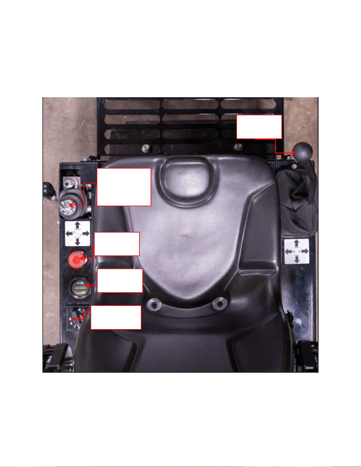
As battery voltage is consumed through machine use, the voltage meter (left side
instrument panel) will display the battery percentage. This is similar to a gas
gauge but when the readout reaches 20% the machine will go into limp mode (slow
the RPMs down) to let the operator know it needs to be driven to where it will be
charged or loaded up on a trailer. The machine must be charged to begin scraping
again. To charge the batteries with the stand-alone charger:
1. Park machine on a level surface
2. Turn machine off (push red Emergency Stop button down)
3. Plug DC connector from the stand-alone battery charger (Gray connector)
into receptacle on front left side of the machine.
4. Insert AC electrical plug from stand-alone charger into wall outlet
conforming to the voltage of the charger being used.
Your Cyclone is equipped with wheel scrapers that scrape whatever debris you run
over like VCT off the tires. If you notice your Cyclone isn’t getting traction or is
carrying debris around you may have to loosen 2 bolts on the wheel scrapers and
slide them against the tires and retighten.
Change Scraping Blades
Lift blade bar to full UP position. Place a block under blade bar assembly for
safety purposes. Push the red button down to stop the electric motor. Loosen the
pinch or clamp bolt at the rear of the blade holder block using a ¾” wrench. Slide
the dull blade out and insert a new blade up against the shoulder stop. Retighten
the pinch bolt, remove wood block for safety, and resume scraping. The large 1-
1/8” blade holder bolt should not need to be more that hand tight. With a little
practice you should be able to change blades in 15 seconds. Dull blades can be
sharpened and reused many times.

11
SECTION VI
CHARGERS AND BATTERIES
BATTERY CHARGER INFORMATION
Summit II Series 1425W Switch Mode Industrial Battery Charger
The charger features Bluetooth wireless communication, which can be accessed
using an Apple® or Android™ smart phone, tablet, or similar device. Download
the ChargerConnect app for your device by scanning the QR code on the charger
or visiting the App Store® or the Google Play™ store and searching for
"ChargerConnect".

12
The charger communication electronics are DC powered, so the charger must be
connected to the battery pack in order to communicate with it via Bluetooth. The
charger was connected to the battery pack from the manufacturer. Open the
ChargerConnect app and select the charger from the list of available units the app
is able to communicate with. The Charger ID has been previously changed via the
app to reflect the serial # of your Cyclone SS. While connected, the Red, Yellow,
and Green LEDs on the charger will slowly blink at the same time until the
Bluetooth communication is disconnected form the charger.
On-Board Charger Operation
1. Ensure that your Cyclone SS that the charger is mounted on is turned off by
pushing the red Emergency Stop button down.
2. Connect the charger AC power cord to an appropriate live AC outlet which
is indicated by the blue “AC PRESENT”LED turning on. The charger will
start automatically as indicated by the yellow “CHARGE STATUS”LED
beginning to blink slowly.
3. Do not disconnect the charger from the batteries while a charge cycle is in
progress.
4. The charge cycle 80% point is indicated by the yellow LED beginning to
blink quickly.
5. The Finish charge cycle phase is indicated by the solid illumination of the
yellow LED.
6. An extended Balance/Equalize charge cycle phase is indicated by the green
“CHARGE COMPLETE”LED beginning to blink quickly.
7. The charger automatically terminates the charge cycle when a battery
reaches full charge, which is indicated by the solid illumination of the green
LED or the green LED beginning to blink slowly indicating a post-charge
phase. Before operating the Cyclone, disconnect the charger AC power cord
from the outlet.
8. Do NOT disconnect the charger from the batteries or from the AC power
until your Cyclone is needed for use. Disconnecting and reconnecting the
charger from the batteries or AC power may start a charge cycle, but
disconnection disrupts the storage mode so optimum battery maintenance is
not achieved.
Storage Mode is designed to keep your battery maintained during storage periods
that last a few weeks to several months at a time. Leaving the on-board charger
plugged in will not harm the batteries and is preferred as they will maintain and
charge the batteries when needed. The Lifeline® AGM batteries in your machine

13
discharge 1 to 3% per month and you do not want to store batteries for an extended
period of time without them being fully charged. The higher the temperature, the
faster the battery will self-discharge.
The Summit on-board charger in your machine has been programmed to charge the
Lifeline® AGM sealed batteries that were installed originally from the factory. If
any other type of battery is installed on the CYCLONE, your charger profile may
need to be changed.
Quick Charge Stand Alone Charger
This model has a changeover tap to
accommodate 208 or 230/240 volt input.
You must check that your incoming power
to the charger matches where the
changeover tap is placed for the charger to
work correctly. Always use a qualified
electrician to install correct AC
connections.
Do not disconnect the plug from the
Cyclone when the stand-alone charger is
on. The resulting arcing could cause the
batteries to explode. Do not expose this
charger to rain if possible.
Make sure the AC cord, DC output leads,
terminals, and connectors are all in good
working condition. Do not use the charger
if there are any signs of stress or damage,
or if wires are cut or have damaged insulation. Using this charger with any of
these symptoms could result in a fire, property damage, or personal injury. Have a
qualified service person make the necessary repairs. See the Quick Charge
Corporation Operating Instructions for additional information and FAQs.
Please see additional information in charger manuals!

14
BATTERY CARE AND MAINTENANCE
DANGER OF EXPLODING BATTERIES
Lead acid batteries can produce explosive mixtures of hydrogen and oxygen. Take
the following precautions:
●Never leave batteries in an airtight or sealed enclosure.
●Charge batteries in accordance with the instructions given in this manual.
●Keep all sparks, flames and cigarettes away from batteries.
●Make sure cables are tightly connected to terminals to avoid sparks.
●Wear proper eye and face protection when installing and servicing batteries.
DANGER OF CHEMICAL BURNS
Lead acid batteries contain sulphuric acid electrolyte which can cause severe burns
to body tissue. Take the following precautions:
●Avoid contact of the electrolyte with skin, eyes or clothing.
●Never remove or damage vent valves.
●In the event of an accident, flush with water and call a physician
immediately.
DANGER OF BURNS IF TERMINALS ARE SHORTED
Lead acid batteries are capable of delivering high currents if the external terminals
are short circuited. The resulting heat can cause severe burns and is a potential fire
hazard. Take the following precautions:
●Do not place metal objects across battery terminals.
●Remove all metallic items such as belt buckles, watches, bracelets and rings
when installing or servicing batteries.
●Wear insulating gloves when installing or servicing batteries.
●Use insulated tools when installing or servicing batteries.
DANGER OF THERMAL RUNAWAY
Thermal runaway is a condition in which the battery temperature increases rapidly
resulting in extreme overheating of the battery. Under rare conditions, the battery
can melt, catch on fire, or even explode. Thermal runaway can only occur if the

15
battery is at high ambient temperature and/or the charging voltage is set too high.
Take the following precautions:
●Charge batteries in accordance with the instructions given in this manual.
●Do not install batteries near heat sources or in direct sunlight that may
artificially elevate their temperature.
●Never use another charger not designated by the manufacturer - OEM
Products Inc.
As of this writing, Concorde does not know of any Lifeline® AGM batteries that
have failed due to thermal runaway. See the LIFELINE® TECHNICAL
MANUAL for full SAFETY INFORMATION.
TEMPERATURE CONSIDERATIONS
The temperature of the battery has a significant impact on its performance and life
capability. Battery capacity is reduced significantly in cold temperatures.
It should be realized that the temperature of the battery itself and ambient
temperature can be vastly different. While ambient temperatures can change very
quickly, battery temperature change is much slower. It takes time for the battery to
absorb temperature and it takes time for the battery to relinquish temperature.
If the battery is exposed to cold climates, the state of charge should be kept at a
maximum to prevent freezing of the electrolyte. A fully charged battery will not
freeze even under the coldest weather conditions, but a discharged battery will
freeze even when moderately cold.
Frozen batteries are not capable of charging or discharging except at very low
rates, and may be permanently damaged by expansion of the electrolyte. A battery
pack with a state of charge of 25% can freeze at 9 degrees Fahrenheit or a battery
pack ran all the way down to cutoff can freeze at 21 degrees Fahrenheit. A 100%
charged battery pack would have to get colder than -94 degrees Fahrenheit to
freeze. SERVICING
Lifeline® AGM batteries do not need electrolyte additions as do flooded lead-acid
batteries, but periodic servicing is essential to assure continued integrity of the
battery system. Servicing should include good record keeping documenting the
life history of the battery system and to identify whether corrective action needs to

16
be taken. See the LIFELINE® TECHNICAL MANUAL for full Servicing
schedule.
CHARGING
You cannot short charge your batteries (like at lunchtime) without long-term
effects on your batteries. It is important to charge batteries back to 100% each and
every time you plug a charger in.
When you have a fully charged battery it is lead and sulfuric acid (Active
material). When you start discharging a battery, the chemical reaction between lead
and sulfuric acid provides energy for your application. The byproduct of this
reaction is lead sulfate. Lead sulfate is a soft material that naturally covers the
plates, both positive and negative, when the battery is being discharged. The
deeper the discharge, the more lead sulfate will cover the plates. Once the load is
turned off and it is time to recharge, lead sulfate is easily converted back into lead
and sulfuric acid. This is why it is important to charge batteries back to 100%. If
you don’t you will not convert all the lead sulfate back into the active material. If a
lead acid battery is not immediately recharged, the lead sulfate will begin to form
hard crystals, which cannot be reconverted by standard charging voltages. The
longer this goes on, the harder it is to get all of your capacity back.

17
SECTION VII
MAINTENANCE SCHEDULES
EVERYDAY MAINTENANCE:
1. Check hydraulic oil level and make sure it is within 2” of the top of the
tank
2. Torque wheel lug bolts to 100 ft. /lbs. and wheel hub nuts (axle nuts) to
at least 200 ft./lbs.
3. Inspect all hydraulic components and hoses for leaks and correct leaks
immediately
EVERY 100 HOUR MAINTENANCE:
1. Grease front caster wheel assemblies (2 places to grease) and inspect for
damage
2. Grease blade bar shaft (behind blade holder assembly)
3. Check and tighten all hydraulic fittings
4. Inspect and tighten all joystick steering linkages
5. Equalize the battery pack by charging to 100% then unplugging power
source and plugging back in to start another charge cycle until
complete.
EVERY 250 HOUR MAINTENANCE:
1. Drain and replace hydraulic oil and filter
BE AWARE OF THE EFFECTS OF HARSH ENVIRONMENTS TO
THE SCRAPER EQUIPMENT.
A. The constant and continuous impacts of ceramic tile removal
could cause premature loosening of bolts and nuts over the entire
machine
B. Use of non-marking (white) tires on ceramic tile, marble, or
sharp-edged debris will result in extreme tire damage. Black tires
are recommended
C. Carpet removal will generally result in front transport casters
being wrapped with stray carpet strings. Remove debris from
front and rear wheels daily to prevent irreparable damage to
bearings and seals.

18
PARTS, OLD AND NEW
CYCLONE JOYSTICK ASSEMBLY
KEY
DESCRIPTION
QTY
PART NUMBER
1
Ball knob
1
CSJ-101
2
Shifter handle
1
CSJ-102
3
Shifter boot
1
CSJ-103
4
Boot clamp
1
CSJ-104
5
Pivot bracket
1
CSJ-105
6
¼” rod end no/stud
4
CSJ-106
7
4-way pivot
1
CSJ-107
8
¼” rod end w/stud
4
CSJ-108
9
Mount, upper cable
1
CSJ-109
11
Switch retainer bolts
2
CSJ-111
12
Switch retainer nuts
2
CSJ-112
13
Back Up alarm switch
1
CYE-109
15
Back up alarm switch mount
1
CSJ-114
18
Cable, left pump -- 52” front
1
CSJ-118
19
Cable, right mount --72” rear
1
CSJ-119
20
Bell Crank assembly with bearings
1
CSJ-120
21
Tube, Linkage 18" lt & rt hand thread
1
CSJ-121
22
Rod end w/stud left hand threads
2
CSJ-122
23
Rod end w/stud right hand threads
2
CSJ-123
24
Link, Pump Control (long)
1
CSJ-124
25
Link, Pump Control (short)
1
CSJ-125
26
Link, Pump Control long 22” aluminum SS model
1
CSJ-124-SS
27
Link, Pump Control short 15.5” aluminum SS model
1
CSJ-125-SS
28
Rod End, Male 5/16” Right hand thread SS model
2
CSJ-129-SS
29
Rod End, Male 5/16” Left hand thread SS model
2
CSJ-130-SS

19
CYCLONE FRAME AND COWLINGS
KEY
DESCRIPTION
QTY
PART NUMBER
1
Caster, front
2
CYF-101
2
Caster wheel, front only
2
CYF-102
3
Tire, Rear Drive Wheel 14 x 4-1/2 x 8 Non Marking
2
CYF-103
4
Tire, Rear Drive Wheel 14 x 4-1/2 x 8 Black
2
CYF-104
5
Cover, front
1
CYF-105
6
Foot Step
1
CYF-106
7
Pins, pivot 1”
2
CYF-107
8
Seat
1
CYF-108
9
Mount plate, seat
1
CYF-109
10
Hinge, seat
1
CYF-110
11
Cover, oil cooler front
1
CYF-111
Cover, oil cooler back
1
CYF-112
12
Cover, oil tank
1
CYF-115
13
Cover, Battery left side
1
CYF-116
14
Cover, Battery right side
1
CYF-117
D-Ring
1
CYF-118
16
Frame
1
CYF-119
19
Weight hangers 2” round bar
4
CYF-122
20
Weight cover, lower left
1
CYF-123
21
Weight cover, lower right
1
CYF-124
22
Blade Bar Mount Plate
1
CYF-125
24
Blade Bar Bottom 24”
1
CYF-126
25
Blade Bar Top 24”
1
CYF-127
26
Blade Bar Top “mount bolts” ¾-10 x 2 ¼”
2
CYF-128
27
Blade Bar Top “clamp bolts” ½-13 x 1 ½
2
CYF-129
28
Blade Bar assembly 8”
1
CYF-130
29
Blade Bar Top 8”
1
CYF-131
30
Blade Bar Mounting Bolts ½-13 x 2
2
CYF-132
31
Blade Bar Pivot Pins
2
CYF-133
32
Bolts, lug, holds wheel to hub
10
CYF-134

20
CYCLONE HYDRAULIC DRIVE COMPONENTS
DESCRIPTION
QTY
PART NUMBER
Pump, front/left hydrostat
1
CYH-101
Pump, rear/right hydrostat
1
CYH-102
Pump, Tandem Hydrostat for SS model
1
CYH-201
Motor, wheel drive
2
CYH-103
Filter, 10 micron element
2 (1 on SS model)
CYH-104
Filter, 3/8” spin on head
2 (1 on SS model)
CYH-105
Cap, hydraulic tank
1
CYH-106
Cylinder, tilt 2x4 (old model)
1
CYH-107
Cylinder, tilt 3x6 (current)
1
CYH-107B
Pins, Tilt Cylinder
4
CYH-108
Cylinder, Lift 3x3x2
2
CYH-109
Pins, Lift Cylinder
2
CYH-110
Cooler, hydraulic oil
1
CYH-111
CYCLONE ELECTRICAL COMPONENTS
DESCRIPTON
QTY
PART NUMBER
36 Volt Electric Motor
1
CYE-101
36 Volt Electric SS Motor
1
CYE-201
6 Volt 400 AH AGM
1
CYE-102
On/Off switch –keyed
1
CYE-103
Key
1
CYE-103A
Solenoid, 36V
1
CYE-104
Meter, Battery 36V Gauge
1
CYE-105
Meter, Battery Engage 36v
1
CYE-105E
Display, Curtis Controller monitor
1 (SS model)
CYE-105-SS
Meter, Hour
1
CYE-106
Beacon, yellow
1
CYE-107
Alarm, Back-up
1
CYE-108
Switch, Back Up Alarm
1
CYE-109
Diode
1
CYE-110
Connector, gray 175
1
CYE-111
Contact, 175
2
CYE-112
Call for charger information
2
Various
This manual suits for next models
1
Table of contents
Popular Floor Machine manuals by other brands

Nilfisk-Advance
Nilfisk-Advance Advance ET610 Instructions for use

HSS Hire
HSS Hire Hire Shops 918 Operating & safety guide

Sapphire Audio
Sapphire Audio 85s user manual

StoneAge
StoneAge FC-SG Operation and maintenance manual

Alto
Alto American-Lincoln 6150 Operator's manual & parts list

HAKO
HAKO PowerBoss Armadillo 6X user manual