OEM ITX-945GC3B N330 User manual

OEM ITX-945GC3B N330 Motherboard
The ownership of all parts of this product, including the
accessories and software, is enjoyed by OEM production
Electronics Co. Ltd. Imitating, replicating, abstracting or
transferring of the product is not permitted without the
consent of OEM. The product specifications and other in-
formation provided in this Manual are only used for refer-
ence and shall be subject to change without prior notice.
The names mentioned in this Manual are only used for
purpose of identification. Some of them may be the trade-
marks of other companies, or their copyrights are owned
by those companies.
We will be appreciate if we are informed about any error
or ambiguous description in whichever part of this Manual,
including that of the hardware and software.
User’ s Manual V1.0
All rights reserved.
Service hot line (US): 800-664-8917
Email: info@OEMproduction.com

1. Gratitude 1
2. Accessories 1
3. Picture of the motherboard 2
4. Features 3
System processor
System memory
System BIOS
Interface of peripheral equipment
Power management
Expansion slot
1. Layout of motherboard 6
2. Installing memory card 7
3. Installing extension interface card 8
Installing PCIE video card
4. Setting motherboard’s jump wire and inserts 9
SATA1/SATA2/SATA3/SATA4 (Serial ATA wire-harness receptacle)
CPU_FAN1/SYS_FAN1(CPU fan’s receptacle / system fan’s receptacle)
CLR_CMOS(CMOS pin)
F_USB1/ F_USB2(Frond-end USB pin)
F_ AU DI O(Pin for front-end sound card)
A TX 24 P(Power receptacle)
F_ PA NE L(Front-end control panel)
I D E 1 (Wire-harness receptacle for hard disk)
5. Rear interfaces of motherboard 14
1. Main menu 16
2. Standard CMOS setup 18
3. Advanced BIOS setup 18
CPU Configuration 18
IDE Configuration 19
IO Chip Configure 20
PC Health Configuration 21
4. Power management 22
5. BOOT setup 23
6. Security setup 25
I. About the product
II. Installing hardware
III. BIOS Setup
Contents

IV. Installing software
7. Chipset setup 26
8. Exit 28
1. Installing driver for motherboard 29
Installing driver for main chip 30
Installing driver for sound card 30
Installing driver for on-board network interface card 31
Installing driver for video card 31
2. HD-AUDIO sound card setup 32

1
Thank you for purchasing ITX-945GC3B N330 Motherboard made by OEM.
Employing INTEL 945GC+ICH7 and on-board IN TELA tom N330 CPU,
this product supports front-end wire harness 1066MHz, dual-channel
memory standards of DDR II 667/533 and USB2.0, and is built with on-
board HD-AUIO sound card.
Your Mini ATOM N330 Motherboard consists of the following accessories.
If any of them is missing, please contact your local distributor as soon as
possible.
1
1.1 Gratitude
1.2 Accessories
Chapter I
About the Product
1. ITX-945GC3B N330 Motherboard
2. User’s Manual V1.0 for Mini ATOM N330 Motherboard
3. Warranty Card/QA Card
4. Data cable for hard disk (80-Pin)
5. SATA hard disk cable
6. Driver’s disk
One piece
One copy
One for each
One piece
One piece
One piece

2
22
3. Picture of the motherboard
Note: The above figure is the picture of ITX-94GC3B motherboard.
This picture is only used for reference and the physical object
shall prevail.

3
4. Features
System processor
1) Built with on-board INTELAtom N330 CPU
System memory
1) Supports one 240-Pin DDR II 667/533 memory;
2) Supports 2GB of memory at maximum;
3) Supports single-channel memory mode.
System BIOS
1) Supports PNP, APM and ATAPI;
2) Supports ACPI and DMI;
3) Automatic detection and supporting hard disk the LBAmode
of which is over 160G;
4) Easy for end-users to upgrading the motherboard with BIOS.
Interface of peripheral equipment
1) One quick IDE port, supporting DMA33/66/100 hard disk,
CD-ROM, ZIP, LS120 and other drivers;
2) Integrated with PCIE kilo-mega network interface card
(RTL8111C);
3) One 16650-compatible UART serial interface;
4) Supports 4 SATA II hard disk interface;
5) 6 high-speed transmission ports (max. 480Mb/s) which sup-
port USB2.0, compatible with USB1.1;
6) One PS/2 keyboard connector;
7) One PS/2 mouse connector;
8) One CMOS pin;
9) One receptacle for system fan;
10) One interface for case panel, compatible with HDD LED and
Speaker.

4
44
11) On-board HD-AUDIO sound card:
(1) Integrating HD-AUDIO sound-effect controller;
(2) Supports Director Sound and Sound Blaster;
(3) Supports NPN and APM 1.2;
(4) Supports Win2000/XP/Vista driver;
(5) Supports Line-in, Line-out and Mic-in;
(6) Supports front audio ports.
Power management
1) Supports APM and ACPT;
2) Compatible with “Green PC”.
Extended interface
One PCI Express x16 graphics card interface.

5
Chapter II
Installing Hardware
Warning
The motherboard consists of a great number of ICs and other
components. These ICs are apt to be damaged by the static
charge. Therefore, the user must make the following prepara-
tions before formal installation:
1. Turn off the power of the computer. It is preferable
the power cord be unplugged.
2. Take care not to contact the metal wires and theirs
joints on the motherboard when handling it.
3. It is preferable that the anti-static wrist strap be worn.
4. Before the ICs are installed, the components of the
motherboard should be placed on the anti-static mat
or bag.
5. When you remove the plug on the ATX power sup-
ply of the motherboard, make sure the switch of the
power supply is in OFF state.
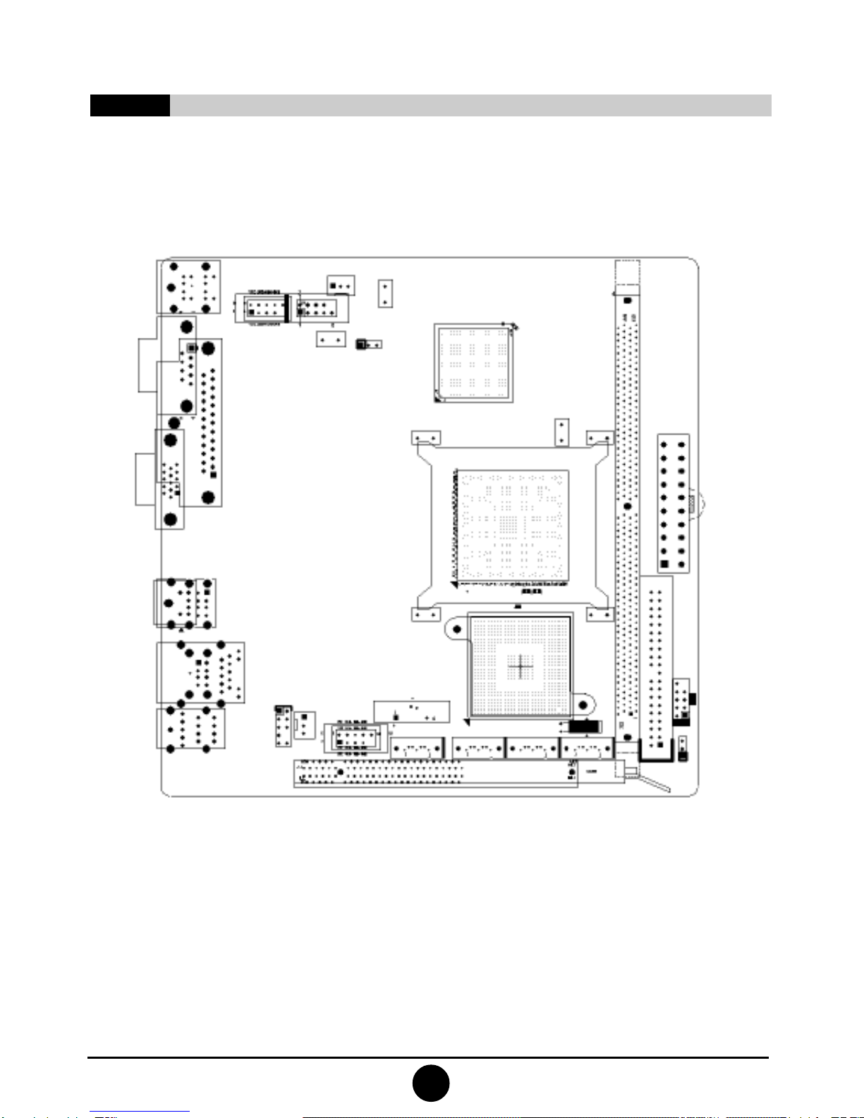
Installing the motherboard onto the computer case:
For most of the computer cases, the multiple fixing holes left
on their bottoms can be used for securing the motherboard and
no short circuit can occur therefrom. During your operation,
take care not to allow the screws to contact any circuit or part
on PCB. When circuits on the surface of the motherboard get
close to the fixing holes, you can use the plastic sheet to sepa-
rate the screws from the board surface so as to avoid damage or
failure of the motherboard.

6
66
1. Layout of motherboard

7
2. Installing memory card
Remove outward the white tenon at
the two ends of the interface slot for
module of the memory card.
Please install the memory card in accordance with the following
procedures:
1) Remove the white tenon at the two ends of the interface slot for
the memory card;
2) Align the golden finger of the memory card to the throve of the
interface slot and pay attention the concave hole of golden finger
should be aligned to the convex point of the slot;
3) Finally, insert the memory card into the interface slot gentlely. If
no error occurs at the moment, insert the card forward in the slot
till the white buckle is automatically engaged in the concave hole
at the two sides of the memory card.
Note
In order to avoid damages to the motherboard or the components,
the user must make sure the power supply to the computer is
turned off before the memory card or other system component is
installed or removed. As the throve is set at the golden finger of the
DDR DIMM memory card, the memory card can only be inserted
into the slot with one direction. During installation, the user only
needs to align the golden finger and the dual-channel throve of the
interface slot and insert it gentlely. To avoid damage, never apply
excessive force in that process.

88
Installing graphics card
This motherboard provides one interface slot for PCIEx 16 graphics
card. When you install the PCIE graphics card, you should note that
throve of the golden finger must be exactly engaged into the interface
slot. In that process, it is preferable that you be in grounded state, and
you should carefully take out the graphics card from the anti-static
bag. Then align the graphics card to the PCIE interface slot and insert
it. After that, tighten the screw on the metal baffle.
3. Installing extension interface card
Bracket
Screw
Graphics
card
Motherboard

9
1) SATA1/SATA2/SATA3/SATA4 (SerialATA wire-harness receptacle)
Serial ATA receptacle can offer a transmission speed of 300MB/sec.
You can connect the Serial ATAdevices to this receptacle.
2) CPU_FAN1/SYS_FAN1(CPU fan’s receptacle)
This receptacle can be used for connecting CPU/system fan.
Its pins’ function are defined below. The user shall make sure
the fan is conforming.
4. Setting motherboard’s jump wire and inserts
Note
The user should note that all receptacles are marked with PIN1. The
symbol “#” indicates the ex-factory default value of the motherboard.

110
3) CLR_CMOS(CMOS port)
The correct time, system hardware and other information are saved in the
CMOS memory of the motherboard. The shutoff the computer’s power
supply won’t cause the loss of this information, for the CMOS is powered
by the battery on the motherboard. Its settings are seen below:
1
Definition
Normal
Clear CMOS
Pin
1-2#
2-3

011
4) F_USB1/ F_USB2(frond-end USB port)
In case the USB ports on the rear panel of the machine case are insufficient,
the user can use the extension USB ports provided by this motherboard.
These ports support USB 2.0 devices. The definitions of the ports are
described below:
Definition
MIC
MIC-BIAS
Output of right channel
Ground
Output of left channel
Pin
2
4
6
8
10
Definition
Ground
5V
-
Empty
-
Pin
1
3
5
7
9
5) F_AU DI O(Port for front-end sound card)
These sound card ports allow you to connect to the wire harness of
the sound card. After connection, you can easily control the audio
output/microphone through the front panel of the host (Note: Don’t
connect the wire to Pin 4).
The definitions of the ports are described below:

112
6) A TX 24 P(Power receptacle)
This receptacle is used for connecting the 24-pin outlet of the power supply.
The definitions of the ports are described below (when power supply with 20-
pin outlet is used, please make sure the numbers are matched correctly):

213
8) I D E 1 (Wire-harness receptacle for hard disk)
One IDE wire-harness receptacle is set on this motherboard. Each receptacle
can be connected to one IDE wire harness and each wire harness can be
connected to two IDE devices. Insert the blue plug of the wire harness into the
IDE1 receptacle on the mother board, and insert the other end into the IDE
device. Normally, Pin 1 of the wire harness is marked with red color. Please
insert into corresponding Pin 1 of this receptacle.
7) F_ PA NE L(Front-end control panel) (Wire-harness receptacle for floppy drive)
This receptacle is used for connecting one end of the wire harness of the floppy
drive. The other end of the wire harness will be connected to the floppy drive.
Normally, Pin 1 of the wire harness is marked with red color. Please insert into
corresponding Pin 1 of this receptacle.

114
1) Receptacle for PS/2 keyboard and PS/2 mouse
This motherboard provides two receptacles respectively for PS/2
keyboard and PS/2 mouse. You can connect the PS/2 devices through
these receptacles.
2) COM interface\VGA interface.
3) LPT interface.
4) USB interface.
5) USB interface/RJ45 network card interface.
6) Audio interface.
5. Rear interfaces of motherboard

415
Chapter III
BIOS Setup
Note
The descriptions relating to BIOS in this Manual can only be used for reference as the
BIOS version of the motherboard is upgraded continuously. OEM provides no guarantee
that the contents in this Manual be consistent with the information you acquire.
BIOS is a basic I/O control program saved in the Flash Memory. Bridging the
motherboard and the operating system, BIOS is used for managing the setup of the
related parameters between them. When the computer is activated, the system is
first controlled by the BIOS program. First, a self-detection called POST is per-
formed to check all hard devices and confirm the parameters of the synchronous
hardware. Once all detections are completed, BIOS will hand over the controlling to
the operating system (OS). The correct setup of BIOS plays a key role in stably
running the system and optimizing its performance.
The CMOS Setup will save the set parameters in the built-in CMOS SRAM on the
motherboard. When the power is shut off, the lithium battery on the motherboard
will supply power CMOS SRAM continuously. The BIOS setup program will
allow you to configure the following items:
1. HD drive, floppy drive and peripheral devices;
2. Video display type and display items;
3. Password protection;
4. Power management characteristics.
A. State of BIOS Setup
When the computer is started up, BIOS will run the self-detection (Post) program.
This program includes series of diagnosis fixed in BIOS. When this program is
executed, the following information will appear if any error is found:
Press F1 to Run Setup
Press F 2 to Load default values and continue
To enter BIOS, you can press F1; to load the default values and enter the system,
you can press F2.After the self-detection process is completed, you can press DEL
to enter the BIOS interface if no error is found. If the indicative information disap-
pears before you can act, you can shut off the computer and turn on it again, or you
can press the key RESET on the machine case. To restart your computer, you can
also simultaneously press <Ctrl>+<Alt>+<Delete>.

116
B. Keys and functions
C.Auxiliary information
Main interface
When the system enters the main interface of Setup, the major selected contents
will be displayed at the lower part of the interface with the change of the options.
Set interface
When you set the value for each column, you can view the preset value of the
column and the values that can be set if you press F1, for example, the BIOS
defaultvaluesor CMOS Setup values.To exit theinterface for auxiliary information,
press [ESC].
When the system enters the interface of CMOS Setup menu, you can see the main
menu on the upper part of the screen, as shown in Figure 3.1. In this main menu, you
can use the left and right direction keys to select the setup items. Once the item is
selected, the lower part of the computer screen will show the details of setting.
Key
(Up key)
(Down key)
(Left key)
(Right key)
ESC
Page Up
Page Down
F1
F7
F8
F9
F10
3.1 Main menu
Function
Move to the previous item
Move to the next item
Move to the left item
Move to the right item
Exit the current interface
Change the setup state, or add the values
Change the setup state, or deduct the values
Display the information of the current setup
Load the set values of previous time
Load the safest values
Load the optimized values
Save the set values and exit the CMOS SETUP state

617
(The selections and their contents may be different from the actual
selections, so they are only used for reference).
Figure 3.1
1. Main (standard CMOS setup)
This item is used for setting the date, time, specifications of hard
disk and floppy disk and type of monitor.
2.Advanced (advanced BIOS setup)
This item is used for setting the advanced functions provided by
BIOS, such as the virus alarm and priority order of disks for startup
process.
3. Power (ACPI ) (power management)
This item is used for settingACPI advanced configuration and power
management.
4. Boot (startup configuration characteristics)
5. Security (setting the administrator/user password)
6. Chipset (setting the performance of the chips)
This item is used for setting the voltage, frequency and other items
of Northbridge, Southbridge, USB and other devices.
7. Exit (option of exit)
This item includes load optimal defaults/load failsafe defaults value/
discard changes/ discard changes and exit.
This manual suits for next models
1
Table of contents
Other OEM Motherboard manuals