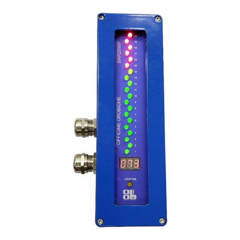
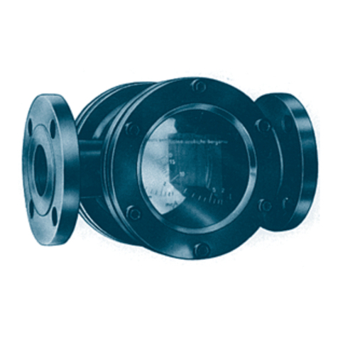
OFFICINE OROBICHE TLQ Series User manual

OFFICINE OROBICHE S.p.A. 1/9
INSTRUCTION MANUAL FOR DIAL-TYPE LEVEL INDICATORS
SERIES TLQ
24010 Ponteranica (Bergamo) ITALY - via Serena, 10 - Phone 0039/035/4530211 - Fax 0039/035/570546 - www.officineorobiche.it-e-mail:info@officineorobiche.it
*****************************************************************************************************************************************************************
MAR.’13 Information subject to change without notice IST/164-I
1. INSTRUMENT DESCRIPTION
Mechanical dial-type level indicators have been designed to measure the level of fluids in small, medium and large
vessels.
The main assets are: great reliability and sturdiness, quick and easy installation and easy-readable level due to the dial
size.
The instrument does not require any power supply.
2. MODEL IDENTIFICATION
TLQ.
TRANSMITTER
Hart Transmitter
Hart/Exia Transmitter
Exia IIC T6 transmitter
No trasmitter
Std. Transmitter
TX
T0
TS
TE
GAS thread
NPT thread
UNI flange
ANSI flange
TG
TN
FU
FA
3
Aisi 316
DIN flange
Carb. Steel
Aisi 316
CONN. MATERIAL
A
J
FLOAT
FD
MEASUR. RANGE
03
05
10
0-3 m single scale
0-5 m double scale
0-10 m double scale
0-20 m double scale
4
5
6
brass
O
J
EXTENSION MATERIAL
PROCESS CONNECTION
1
Special float
S
H
up to 5 m
up to 20 m
20
AISI 316L Ø85x110mm
AISI 316L Ø105mm
AISI 316L Ø140mm
AISI 316L Ø300mm
TH
1-2 Exd IIC T6 alarms
1-4 NPN proximity alarms
ALARMS
No alarms
CS1-4
CE1-2
1-4 Standard alarms
C0
T0
CP1-4
CN1-4
1-4 PNP proximity alarms
C0
XX
VERSION
CR1-4
1-4 NAMUR proximity alarms
S
N0N-STANDARD VERSION
03
O
TG
A
1

OFFICINE OROBICHE S.p.A. 2/9
24010 Ponteranica (Bergamo) ITALY - via Serena, 10 - Phone 0039/035/4530211 - Fax 0039/035/570546 - www.officineorobiche.it-e-mail:info@officineorobiche.it
******************************************************************************************************************************************************************
MAR.’13 Information subject to change without notice IST/164-I
3. OPERATING PRINCIPLE
Operation is based on the buoyancy principle.
The float is combined with a very high-precision clockworks gear-operated
system, which assure an accurate and repeatable level measurement in the
vessel.
The float (1), which contains a permanent magnet (2), slides along a rod (3)
that holds inside a further magnet (4) connected to a rod (5).
The float’s movement, which follows the fluid’s level, causes the inner
magnet (4) to move (by magnetic coupling).
The movement of the rope, which is wound around a pulley (6) with a
return device, causes the hands of the clockworks assembly to move and
indicate the fluid’s level in the vessel.
4. INSTALLATION
4.1 ASSEMBLING
Before installation, ensure the vessel connection is compatible with that of the instrument and that use is compatible with
data printed on the rating plate (pressure, temperature, density and the like.).
The device shall never be used with fluids tending to adhere or crystallzie, as that would block the float that slides along
the sliding rod.
The TLQ-series level indicator shall be installed in the upright position. (3° maximum angle).
The device is typically mounted on top, for both TLQ-S and TLQ-H models (fig.A). The device can also have the dial
mounted in the bottom part of the vessel (fig.B) (for model TLQ-H only).
FIG. A FIG. B

OFFICINE OROBICHE S.p.A. 3/9
24010 Ponteranica (Bergamo) ITALY - via Serena, 10 - Phone 0039/035/4530211 - Fax 0039/035/570546 - www.officineorobiche.it-e-mail:info@officineorobiche.it
******************************************************************************************************************************************************************
MAR.’13 Information subject to change without notice IST/164-I
Assembling sequence:
1. Insert the float into the rod with the reference text (“TOP”) upwards,
then place the retainer in the dedicated seat located at the lower end of
the rod.
2. Insert the rod with the float into the vessel and secure the whole set. In
cases when the float is larger than the diameter of the inlet nozzle, insert
it through the manhole on a vessel's side.
3. Unwind the rope from the head piece connected to the inner magnet (1),
and slowly make it run inside the rod until it meets the buffing action
exerted by the float’s inside magnet (2). Pull back some 30-40 cm of
wire and drop the magnet which, by its own weight will win the float’s
magnetic field and will place itself right below it (see side picture).
Make sure the coupling has been properly made by slightly pulling the
wire, which will offer some resistance due to the repulsion between the
magnets.
4. Release the wire very slowly. It will wind round the pulley until it gets
tightened.
5. Screw the instrument’s neck onto the coupling flange.
6Remove the round cover opposite to the pointers.
7Remove the LOCK SCREW to release the cable, set the BRAKE
SCREW to allow the right sliding. (See Fig.1)
Fig.1
The instrument has a “dead zone” where no level
measurement can be made (L1).
This is due to the distance between the floating point of the
float and the vessel bottom.
The measurement scales provided on the dial are of 4 types:
-0-3m with hand and single scale; STD graduation 10mm
-0-5m with two hands and two scales; a 0-100 centimetre scale (external black
sector) and a 0-5 metre scale (internal red sector))
-0-10m with two hands and two scales; a 0-100 centimetre scale (external black
sector) and a and a 0-10 metre scale (internal red sector)
-0-20m with two hands and two scales; a 0-100 centimetre scale (external black
sector) and a 0-20 metre scale (internal red sector).
In cases when the level to be measured is e.g. 4.5 m, the internal metre hand
shall never reach 100% on the dial, but a little above ¾ , in spite of the fact that
4.5 metres make up 100% of the measurement required. This occurs because
the instrument used has a fixed range, in this case equalling 5 m. (see picture
beside).

OFFICINE OROBICHE S.p.A. 4/9
24010 Ponteranica (Bergamo) ITALY - via Serena, 10 - Phone 0039/035/4530211 - Fax 0039/035/570546 - www.officineorobiche.it-e-mail:info@officineorobiche.it
******************************************************************************************************************************************************************
MAR.’13 Information subject to change without notice IST/164-I
4.2 WIRING
The wiring shall be performed in accordance with the diagrams provided, and the cables shall suit the intended use of the
instrument (as regards temperature, environment and the like).
The electrical wiring shall be carried out in accordance with the regulations in force in the country of installation.
Shielded cables are to be preferred to ordinary ones to avoid failures caused by peak currents.
After wiring, carefully close the housing and the cable gland.
Sensors are located in the rear of the dial, where you can easily accede by unscrewing the rear cover.
Notes for environments featuring explosion risks (Ex)
The connections shall be made through cable entrances or tube piping in compliance with the EN 60079-14 standard.
The cable entrance shall not affect the specific properties of the protection method as indicated in the EN 60079-1
When the cable inlet is made by using a cable gland, the latter shall be correctly chosen as a function of the system
type and of the cable type. The cable gland shall be screwed tight to allow the sealing rings to exert the required
pressure.
The ground connection must be connected to the general system ground with a conductor of suitable section (normally
the same section as the mains connection).
- ALLARMS WITH MICROSWITCH Series CS (Standard type)
- ALLARMS WITH MICROSWITCH Series CE (Exd type)
The microswitches have been developed for use in hazardous areas
(Exd). The instrument case only provides mechanical protection
whereas the miniature switch and its cable are melted into a single
component. The miniature switch cable that exits the case shall be
wired in accordance with EN60079-14.
- ALARMS WITH PROXIMITY SENSOR
NAMUR TYPE Series CR PNP TYPE Series CP NPN TYPE Series CN

OFFICINE OROBICHE S.p.A. 5/9
24010 Ponteranica (Bergamo) ITALY - via Serena, 10 - Phone 0039/035/4530211 - Fax 0039/035/570546 - www.officineorobiche.it-e-mail:info@officineorobiche.it
******************************************************************************************************************************************************************
MAR.’13 Information subject to change without notice IST/164-I
-TRANSMITTER 4/20mA series TS-TE-T4-TX
x TS-T4 x TE-TX
wiring
5 SETTING AT WORK
Make sure that the use of the instrument does not exceed the intended use (i.e. pressure and temperature values and the
like) and ensure the measurement made is correct by changing a few times the level of the fluid in the vessel.
If this cannot be done, you can move the float by hand.
As far as the version with transmitter is concerned, series connect an ammeter in the line to check it for proper
operation.
The standard setting ranges from 4mA = 0% to 20mA = 100% (on request, the setting can be reversed).
Comply with the power supply value 10-35 Volt for standard models and d10-28 Volt for explosion-proof models.
The maximum load is given by the following formula:
RLOAD = (V SUPPLY –8) / 0.023
The instrument shall never work close to strong magnetic fields (minimum distance: 1 m)
It can only be used with special feeders or indicators.
As far as the version with alarms is concerned, check the alarms for proper operation by making the float slowly slide
along the rod to make sure the alarm switching takes place.
6.CALIBRATION
Adjusting the pointing head
Make sure the float is in the “minimum level” position, then remove the front lid and loosen the hand fastening screw
located beneath the latter. Align the hand on the “ZERO” or minimum level position if other than zero); tighten the
locking pins taking care not to damage the hand.
IN the models equipped with two hands, (RED HAND = metres and BLACK hand = centimetres), in tightening the
locking pins, take care to maintain the hands on the fastening pin correctly spaced from one another, to prevent them from
locking out while turning.

OFFICINE OROBICHE S.p.A. 6/9
24010 Ponteranica (Bergamo) ITALY - via Serena, 10 - Phone 0039/035/4530211 - Fax 0039/035/570546 - www.officineorobiche.it-e-mail:info@officineorobiche.it
******************************************************************************************************************************************************************
MAR.’13 Information subject to change without notice IST/164-I
Calibrating alarm contacts
Alarm contacts are generally factory pre-set.
In case of unexpected calibration to be performed at the building stage, take the following actions:
-remove the rear cover and loosen the cam block screws;
-place the float at the desired heights and turn the cams until the contact operates the switching;
as regards the maximum level actuation, turn the upper cam in the counter-clockwise direction;
as regards the minimum level actuation, turn the lower cam clockwise.
-tighten the cam block screws and ensure the contact operates at the desired point by manually sliding the float along the
slide rod.
Calibrating the 4/20 ma transmitter
The version with the 4/20mA transmitter is already factory set and does not require any further settings. They are
generally calibrated to send a 4 mA signal when the vessel is empty and a 20 mA one when the vessel is full.
Notes for Environments featuring explosion risks (Ex)
The testing equipment for the functional test shall be appropriate or certified for use in dangerous areas. Only qualified
persons can carry out this work. The competent technical staff shall connect and disconnect the electrical lines.
7.MAINTENANCE
Mechanical dial-type level indicators do not generally require any scheduled maintenance.
Periodically check, once every six months approximately, that the rod and the float are clean and the instrument operates
properly.
Notes for Environments featuring explosions risks (Ex)
Tests and maintenance over explosion proof sensors shall be carried out according to the criteria set forth in the EN
60079-17 standard.
-Terminals and wiring well tightened to avoid overheating.
-All replacement parts shall be original spare parts.
-Repairs of broken parts are not allowed.
7.1 WARNINGS
- NEVER open the lid without ascertaining that voltage has been disconnected;
- NEVER leave the housing without its own lid for longer than the inspection time:
- NEVER use the instrument at a temperature or a pressure that exceeds the values specified on the rating plate;
- NEVER perform settings or replace parts without having read the instructions beforehand; in case of doubts, please
contact our customer service department;
-NEVER lubricate any part of the instrument;
- If the instrument is used with very low or high temperatures, take all precautionary measures required to guarantee
personal protection to the personnel on duty during the various maintenance stages.
7.2 FLOAT REPLACEMENT
-Dismount the instrument and extract the rod and float assembly;
-Take care not to bend or hit the rod in a violent manner;
-Extract the float by unscrewing the retainer located on the rod bottom;
-Insert the new float (maintain the TOP position of the rod).
-Reassemble the instrument.
-Go through the steps described in paragraph Assembling sequence.

OFFICINE OROBICHE S.p.A. 7/9
24010 Ponteranica (Bergamo) ITALY - via Serena, 10 - Phone 0039/035/4530211 - Fax 0039/035/570546 - www.officineorobiche.it-e-mail:info@officineorobiche.it
******************************************************************************************************************************************************************
MAR.’13 Information subject to change without notice IST/164-I
8 DIMENSIONAL DRAWING
Dimensioning values required
C=Connections
L=Range
E=Extension
F=Float
D=Extension connection
9. SPARE PARTS
ATHREADED THREADED
FTHREADED THREADED
FLANGED FLANGED
TLQ-H
TLQ-S
Ø160
Ø220
UNI DN 20-150 PN10-16
1.1/4" GAS-F
FLANGED
UNI DN 32-150 PN10-16
ANSI 3/4" - 6" ANSI 150
Ø85x110 / Ø105
UNI DN 20-25 PN10-16
ANSI 3/4" - 1" ANSI 150
FLANGED
3/4 GAS-M
ANSI 3/4" - 1" ANSI 150
UNI DN 20-25 PN10-16
ANSI 1"1/4 - 6" ANSI 150
0-10 m
0-20 m
Ø140 / Ø300
C
L
D
0-3 m
0-5 m

OFFICINE OROBICHE S.p.A. 8/9
24010 Ponteranica (Bergamo) ITALY - via Serena, 10 - Phone 0039/035/4530211 - Fax 0039/035/570546 - www.officineorobiche.it-e-mail:info@officineorobiche.it
******************************************************************************************************************************************************************
MAR.’13 Information subject to change without notice IST/164-I
Always mention the instrument serial number in
your request for spare parts.
This number is provided on the instrument rating
plate that is fastened to the bottom of the unit and
is a five-digit number preceded by the letter
”F”(e.g..:F45678).
10. TROUBLESHOOTING
Level indicators of the TLQ series are not normally exposed to faults.
In cases when the measurement is not taken, carry out the test as described
in paragraph 7 MAINTENANCE
11. DISPOSAL
When the instruments have come to the end of their service life, they need to undergo disposal. Always comply with the
applicable regulations in force.
During the disposal stages, specially mind the polymers, resins and rubbers used in the manufacture (such as PVC,
PTFE, PP, PVDF, neoprene, Viton, etc.).
Separate the mechanical part from the electronics, which need to undergo disposal in compliance with thaw regulations
in force.
All metal parts, after removal of seals and gaskets, special protective coatings requested by the customer and all other
plastic parts, can be recycled.
12. GUARANTEE
All level indicators are guaranteed to be free from manufacturing faults over a period of 12 months from the date of shipment.
In the event of failures, implying return of goods within the limit specified above, OFFICINE OROBICHE will replace
(shipment fees not included) all damaged parts free, provided that the failure does not ensue from incorrect use.
OFFICINE OROBICHE shall never be held responsible for any incorrect use of their products when these are used for
purposes other than those mentioned in the specifications approved at the order stage.
In these cases, no complaints will ever be taken into consideration.
No damage and/or fee, whether direct or indirect, ensuing from an incorrect installation or use shall ever be debited to
OFFICINE OROBICHE.
The instrument can be used for a maximum life period of 10 years dating from delivery.
When this period is over, there are two alternative options:
1) Replace it with a new instrument.
2) Have the old instrument overhauled by OFFICINE OROBICHE
INSTRUMENT RETURN PROCEDURE
The instrument returning to the factory shall bear, in attachment, the following data:

OFFICINE OROBICHE S.p.A. 9/9
24010 Ponteranica (Bergamo) ITALY - via Serena, 10 - Phone 0039/035/4530211 - Fax 0039/035/570546 - www.officineorobiche.it-e-mail:info@officineorobiche.it
******************************************************************************************************************************************************************
MAR.’13 Information subject to change without notice IST/164-I
1) Buyer’s name.
2) Description of the material.
3) Detected fault.
4) Process data.
5) Specification of the fluids that have been used with the instrument.
The instrument shall be returned perfectly clean and free from dust or deposits. Otherwise, OFFICINE OROBICHE
reserves the right not to carry out the servicing and return the instrument to the sender.
FINAL REMARKS
Each instrument is supplied fully assembled and equipped with all the needed accessories.
Some parts are sold separately under special circumstances only.
Therefore, we warn you to carefully inspect the supply and notify us at once if discrepancies are found.
N.B. IN CASES WHEN THE INSTRUMENTS ARE MEANT TO BE USED IN AREAS FEATURING
POTENTIALLY EXPLOSIVE ATHMOSPHERES, THE USER SHALL COMPLY WITH THE ADDITIONAL
SAFETY INSTRUCTIONS ATTACHED TO THE STANDARD ONES.
This manual suits for next models
2
Table of contents
Other OFFICINE OROBICHE Measuring Instrument manuals