OfiTE 700-410 User manual

OFITE Spectral Gamma Ray Logger
Part No.: 700-410
Instruction Manual
Updated 9/6/2022
Ver. 2
OFI Testing Equipment, Inc.
11302 Steeplecrest Dr. · Houston, Texas · 77065 · U.S.A.
Tele: 832.320.7300 · Fax: 713.880.9886 · www.ote.com
©Copyright OFITE 2014

OFITE, 11302 Steeplecrest Dr., Houston, TX 77065 USA / Tel: 832-320-7300 / Fax: 713-880-9886 / www.ote.com 1
Introduction.....................................................................................2
Description......................................................................................2
Specications .................................................................................2
Components ...................................................................................2
Quick Start ......................................................................................3
Operation.........................................................................................4
Data Export .....................................................................................7
Manual
Control.............................................................................................8
Calibration.....................................................................................10
Spectral.....................................................................................10
Belt............................................................................................15
Software Setup .............................................................................16
Troubleshooting ...........................................................................20
Belt Adjustment .........................................................................20
Idler Adjustment ........................................................................21
Limit Switch...............................................................................21
Belt Speed ................................................................................22
Maintenance..................................................................................23
Warranty and Return Policy ........................................................24
Table of
Contents

OFITE, 11302 Steeplecrest Dr., Houston, TX 77065 USA / Tel: 832-320-7300 / Fax: 713-880-9886 / www.ote.com 2
The natural gamma ray radiation emitted from rocks varies with the lithology.
The radiation comes from the radioactive decay of Potassium, Uranium, and
Thorium, which are present as trace elements. Shale typically contains more
of these elements than clean sandstone or limestone. Generally, formations
with higher shale content release more radiation.
A gamma ray well log is a recording of the natural gamma radiation of the
formation around the well bore and is almost always run in conjunction with
other well logs. Because the gamma ray log does not change with well treat-
ment or production, it can be used to correlate the depths of the other well
logs and the core gamma ray log from the same hole.
The OFITE Gamma Ray Core Logger measures the energy level and quan-
tity of the radiation emitted from a core sample and calculates the quantity of
each of the elements. The amounts of each of these elements and the total
gamma-ray count are then plotted as a function of depth.
To begin a test, the operator arranges the core samples onto the conveyor
belt in order of depth. The unit will record background radiation for 15 minutes
in order to establish a base reading. Then the conveyor belt pulls the samples
through the machine while the computer shows the results on the screen. At
the end of the test, the results are graphed and can be printed or exported.
The total gamma-ray log is also available.
Maximum Core Diameter: 6" (15.2 cm)
Maximum Belt Speed: 7 fpm (2.1 mpm)
System Dimensions: 23.6" × 47.2" × 118.1" (60 cm × 120 cm × 300 cm)
System Weight: 992 lbs (450 kg)
Gamma Ray Detector
Type and Size: NaI 3" × 3" (7.6 cm × 7.6 cm)
#120-00-033 Pillow Block Bearings, Qty: 3
#700-400-014 Conveyor Belt
#700-400-018 Photo Sensor, Qty: 2
#700-410-068 Calibration Gauge, Sample Size 4.5
#700-410-069 Calibration Gauge, Sample Size 2.375
#700-410-401 Calibration Standard, Potassium
#700-410-402 Calibration Standard, Thorium
#700-410-403 Calibration Standard, Uranium
#700-410-404 Calibration Standard, Background
#900-1908 Desktop Computer
#900-2202 Computer Monitor
Replacement Parts:
#700-400-017 Distance Sensor
#700-400-021 Motor
#700-410-001 Multi-Channel Analyzer
Introduction
Description
Components
Specications
OFITE, 11302 Steeplecrest Dr., Houston, TX 77065 USA / Tel: 832-320-7300 / Fax: 713-880-9886 / www.ote.com 3
Quick Start 1. Always run a spectral calibration the night before running a Spectral Log
test. A spectral calibration is not necessary for the Total Gamma Log test.
2. Place the rst core on the belt directly under the sensor. Start with the
most shallow core rst. Orient the core so that the shallow end goes
under the shield rst.
3. Click the “Start Test” button on the Main Screen.
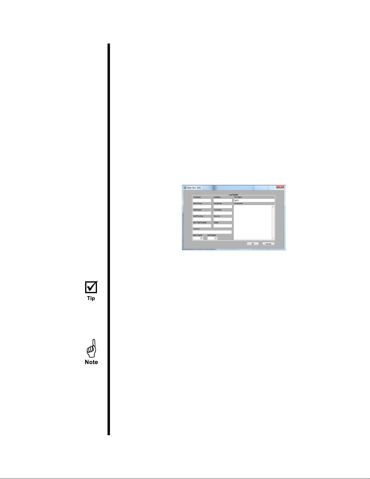
4. Enter the well information. This information will print on the well log at the
end of the test.
5. Enter the start and end depth.
6. Enter a le name and click OK.
7. Continue to load cores onto the belt.
8. Remove cores as they emerge from the shield. Be sure to replace the
core in the proper box and in the correct orientation.
9. When the last core sample has left the shield, click the “Stop” button.
If a core reaches the end of the conveyor, an electronic eye will stop the belt.
The software will continue to collect data and correct for the elapsed time.
OFITE, 11302 Steeplecrest Dr., Houston, TX 77065 USA / Tel: 832-320-7300 / Fax: 713-880-9886 / www.ote.com 4
Operation Always run a spectral calibration the night before running a Spectral Log test.
A spectral calibration is not necessary for a Total Gamma Log test.
1. Place the rst core on the belt directly under the sensor. Start with the
most shallow core rst. Orient the core so that the shallow end goes
under the shield rst.
2. Click the “Start Test” button on the Main Screen.
3. Enter the well information. This information will print on the well log at the
end of the test.
4. Enter the start and end depth.
5. Enter a le name and click OK.
6. Continue to load cores onto the belt.
Make sure each core is properly aligned on the belt according to its depth
in the log. For example, if six inches are missing from the bottom of a
core, leave six inches of empty space on the belt between that core and
the next.
7. Remove cores as they emerge from the shield. Be sure to replace the
core in the proper box and in the correct orientation.
If a core reaches the end of the conveyor, an electronic eye will stop the
belt. The software will continue to collect data and correct for the elapsed
time.
8. When the last core sample has left the shield, click the “Stop” button.

OFITE, 11302 Steeplecrest Dr., Houston, TX 77065 USA / Tel: 832-320-7300 / Fax: 713-880-9886 / www.ote.com 5
Log Header: This displays the information entered on the Start Test screen.
Drive Controls: These options provide manual control of the belt. Manual
control is disabled as soon as a test is started.
- Drive Mode:
- Position: Moves the belt a specied number of feet at maximum
velocity.
- Velocity: Moves the belt at the specied velocity until stopped.
- Vel (ft/min): The velocity of the belt when Drive Mode is set to Velocity.
- Pos (rel-ft): The distance to move the belt when Drive Mode is set to
Position.
- Execute: Check this box to begin moving the belt. Uncheck it to stop
the belt.

OFITE, 11302 Steeplecrest Dr., Houston, TX 77065 USA / Tel: 832-320-7300 / Fax: 713-880-9886 / www.ote.com 6
Scan Type: These options specify what type of test to run.
- Total Gamma: The belt will move at one foot per minute and the
graph will only show total gamma.
- Spectral Gamma: The belt will move at one foot per ve minutes and
the graph will show both total and spectral gamma.
- Custom Scan: Allows you to specify a custom test.
- Average Time: The amount of time to accumulate data before
recording a data point.
- Vel (ft/min): The speed of the belt during the test.
Sensor Values:
Sample Height: Displays the height of the current core
Current Depth: Displays the calculated depth based on the start depth
entered at the beginning of the test
End of Travel Trip: Indicates the sensor at the end of the belt has been
triggered and the motor has stopped
Data:
Total Gamma (cps): Total gamma measurement (in Counts per Second)
Potassium (%): Concentration of Potassium in the sample
Uranium (ppm): Concentration of Uranium in the sample
Thorium (ppm): Concentration of Thorium in the sample
Plot Segment Settings:
Oset: Move the slider to scroll to dierent points on the gamma log.
Window Size: Move the slider to show more or less data points on the
gamma log.
Pause: Check this box to pause the test. The unit will stop collecting data
and the belt will stop moving the samples.
OFITE, 11302 Steeplecrest Dr., Houston, TX 77065 USA / Tel: 832-320-7300 / Fax: 713-880-9886 / www.ote.com 7
Data Export At the end of a test, the test data will automatically be saved in a le on the
computer hard drive. This le can then be imported into the Log Plot software
installed on the computer.
For more information, refer to the Log Plot documentation.
1. After the test is complete, open the Log Plot software.
2. Select “Open” from the “File” menu.
3. In the “Files of Type” eld select “Log Design (*.ldfx)”. Find the le
“Gamma Plot.ldfx” and open it.
4. Select “Open” from the “File” menu again.
5. Find the le “Form.dat” and open it.
6. Open Microsoft Excel and open the data le from the Gamma Ray Logger
software. The data le is located in the folder specied on the options
screen. See page 16 for details.
7. Select all of the data in the data le and copy it to the clipboard.
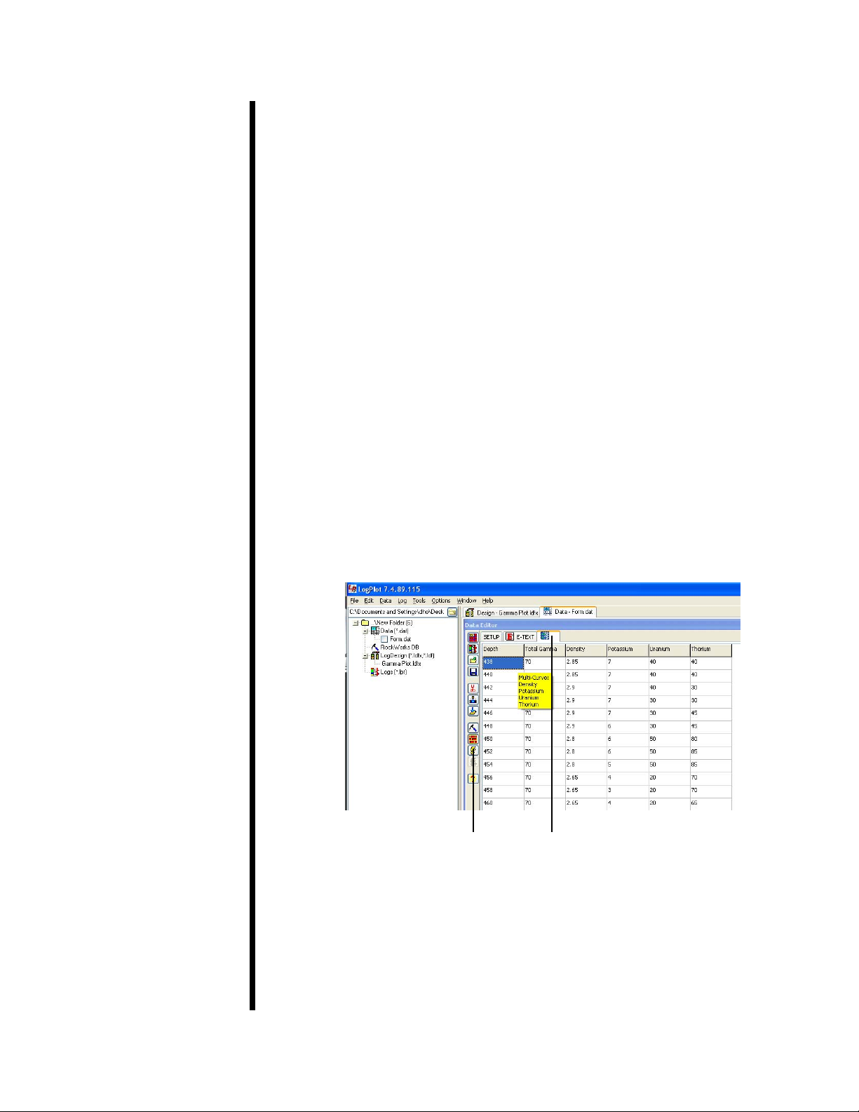
8. In the Log Plot software, click the form tab and paste the test data into the
form.
9. Click the “Compile a Log” button.
10. Enter the starting depth in the “Top of Interval” eld. Enter the ending
depth in the “Bottom of Interval” eld. Make sure the “Positive Depths”
eld is checked.
11. Click OK to compile the log.
Compile Log Button Form Tab

OFITE, 11302 Steeplecrest Dr., Houston, TX 77065 USA / Tel: 832-320-7300 / Fax: 713-880-9886 / www.ote.com 8
Manual
Control
The Gamma Ray Logger can also be used to take manual measurements of
a single core sample.
1. Select “DigiBASE Manual Control” from the “Options” menu.
2. Place the core under the shield.
3. Click the “Start” button.
DigiBASE Info: This information comes from the DigiBASE scanner within
the Gamma Ray Logger. This information is for debugging purposes only.
DigiBASE Realtime: This information shows the current runtime parameters
for the DigiBASE scanner. This information is for debugging purposes only.
True Time: The scanner accumulates data over a specied period of time.
At the end of this interval, the data is recorded as a single data point and the
process starts over. This is called True Time. To set the True Time, enter a
value in this eld and click the “Set True Time” button.
High Voltage Setting: This is the amount of voltage being sent to the photo
multiplier.
Gain Fine: The amplier gain.
Get Versions: Populates the “DigiBASE Info” box

OFITE, 11302 Steeplecrest Dr., Houston, TX 77065 USA / Tel: 832-320-7300 / Fax: 713-880-9886 / www.ote.com 9
Enable HV: Turns High Voltage mode on
Disable HV: Turns High Voltage mode o. When High Voltage mode is o,
the scanner will not collect any data.
Clear: Clears data from the graphs
Start: Starts logging data. Logging will stop at the end of the True Time
interval.
Stop: Stop logging data.
Standard: Choose a standard for a manual calibration.
Export Standard: Save the current data as a calibration for the selected
standard.
Table of contents


