INSTRUCTION MANUAL
9
*If the water network doesn’t reach that recommended pressure, you can use a water
pump (see the FAQ section for more information).
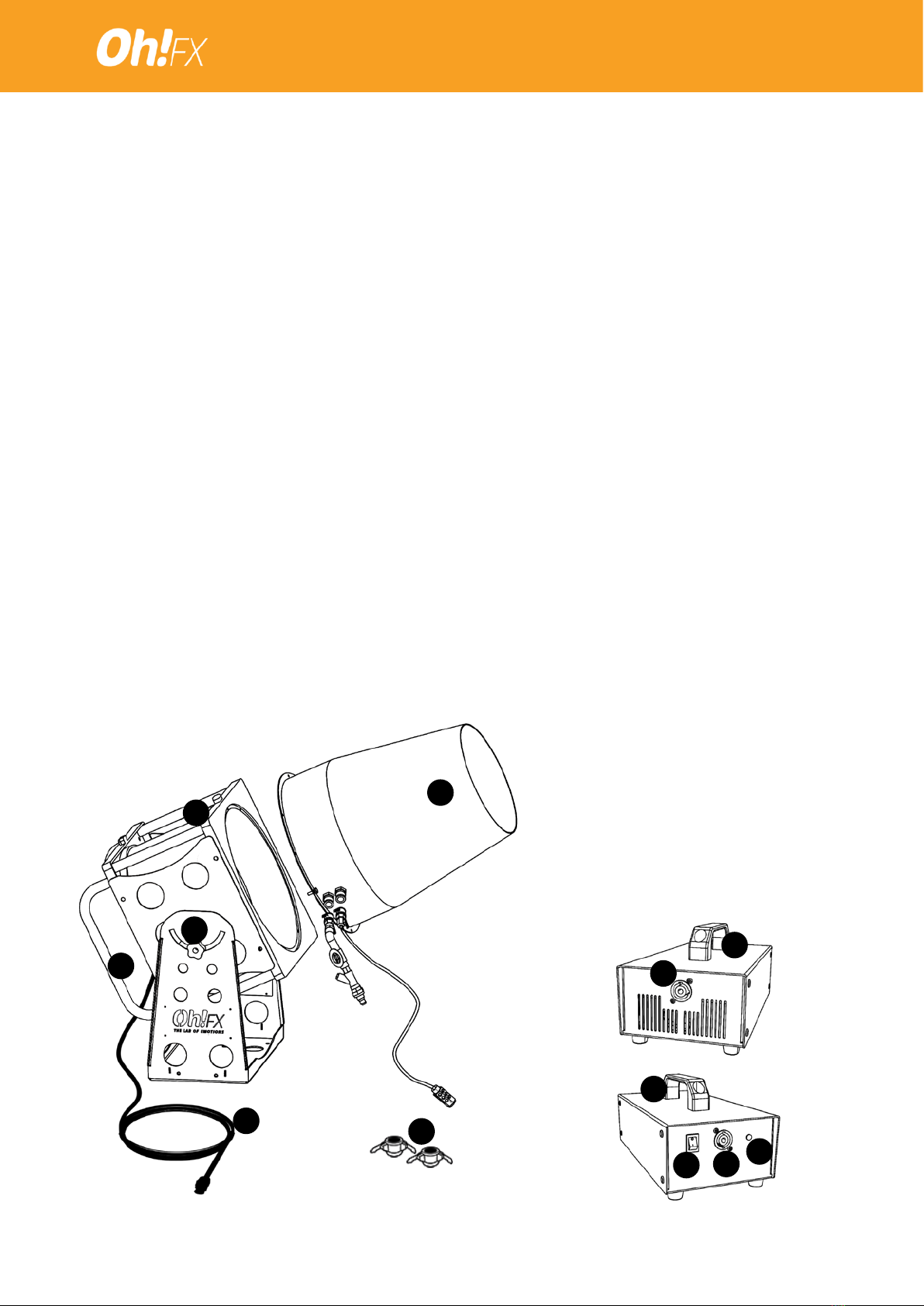
3.1.1. Connect the inlet water tap (17) to the machine’s water connection
(WATER) (13).
3.1.2. With the inlet water tap (17) in “closed” position, connect a water hose to the
free socket of the inlet water tap (17) and turn on the general tap of its water point
(water network or pump).
3.1.3. The PREMIX connection (15) must be covered with a stopper cap (16).
*The PREMIX connection is only used to work with a pump and a tank with a mixture
of water and foam uid (premix).
3.1.4. Connect the foam uid absorption tube (18) to the foam uid connection
(FLUID) (14).
3.1.5. Insert the lter at the end of the foam uid absorption tube (18) into the ready-
to-use foam uid container and check that the inlet foam uid tap (19) is fully open.
3.2. Connecting the SIROCCO machine with PREMIX:
*The machine is fed with the nal mixture (water + foam uid) directly by means of a pump.
See the FAQ section for the specications of the recommended pump.
3.2.1. Connect the inlet water tap (17) to the machine’s PREMIX connection (15).
3.2.2. With the inlet water tap (17) in “closed” position, connect the hose coming
from the PREMIX tank to the free socket of the inlet water tap (17) and turn on the
pump (not included).
3.2.3. The water connection (WATER) (13) and foam uid connection (FLUID) (14)
must be covered with the stopper caps (16) supplied.
4. ELECTRICAL CONNECTION:
4.1. Position the power supply (1) so that it is protected and covered from water and
cannot get wet.
4.2. Connect the power supply (1) to the electric current by means of the power input (2).
4.3. Make sure that the power socket is earthed.
4.4. Turn on the power supply switch (3) and check that the indicator LED (4) is on.
4.5. Connect the SIROCCO power cord (7) to the low voltage power output (5) of the
power supply.
5. OPERATION:
5.1. Turn the speed regulator and switch (8) to maximum.
5.2. Once the motor is at full speed, open the inlet water tap (17).
5.3- The machine will draw a little water and immediately after that it will start to produce
foam.
5.4. You can adjust the distance and density of the foam by adjusting the speed regulator
and switch (8) and the inlet water tap(17).
6. STOPPING AND DISASSEMBLY:
6.1. Close the inlet water tap (17).
6.2. Turn the speed regulator and switch (8) to zero to turn o the motor.
6.3. Turn o the power supply (1) and disconnect the machine.