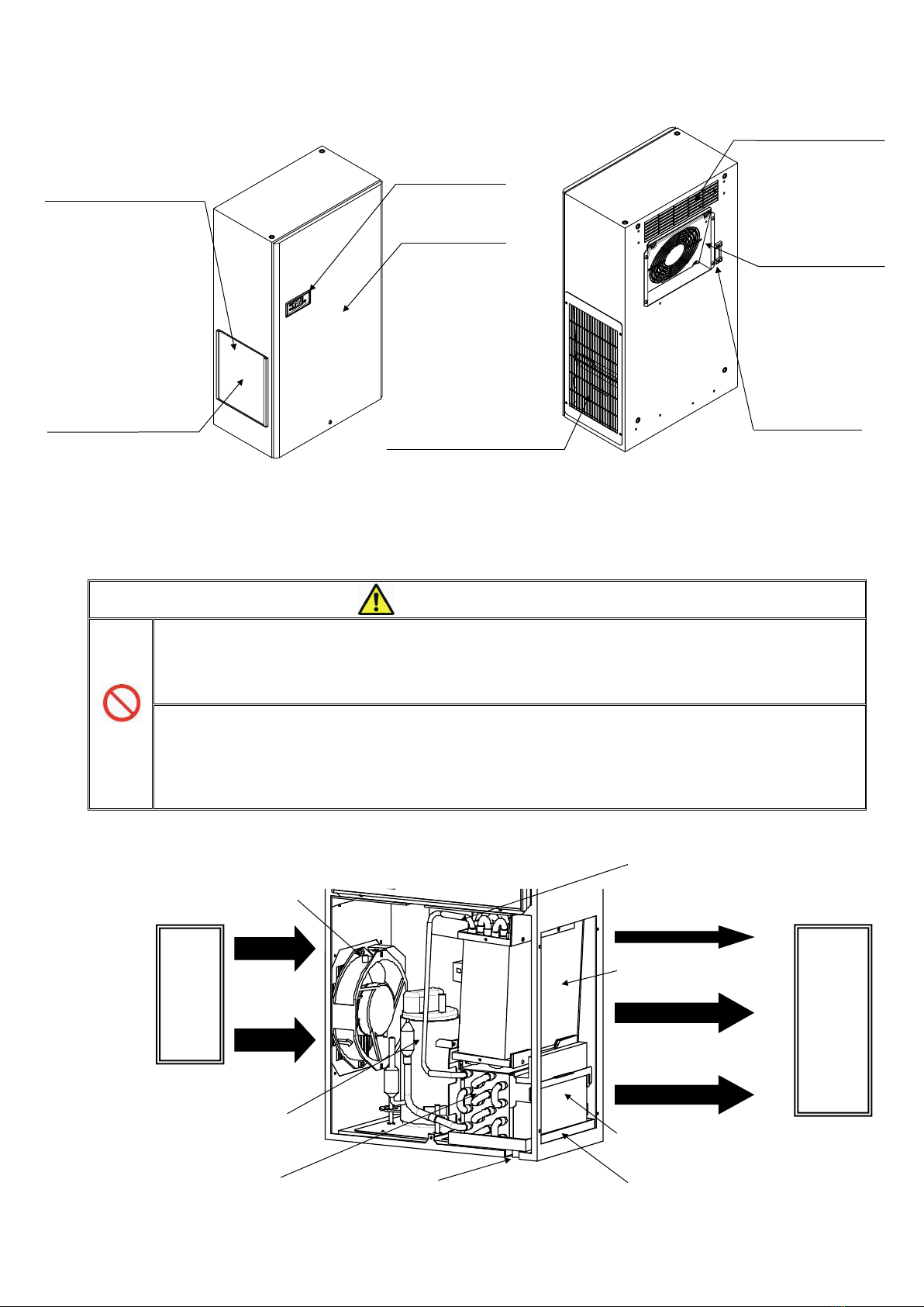
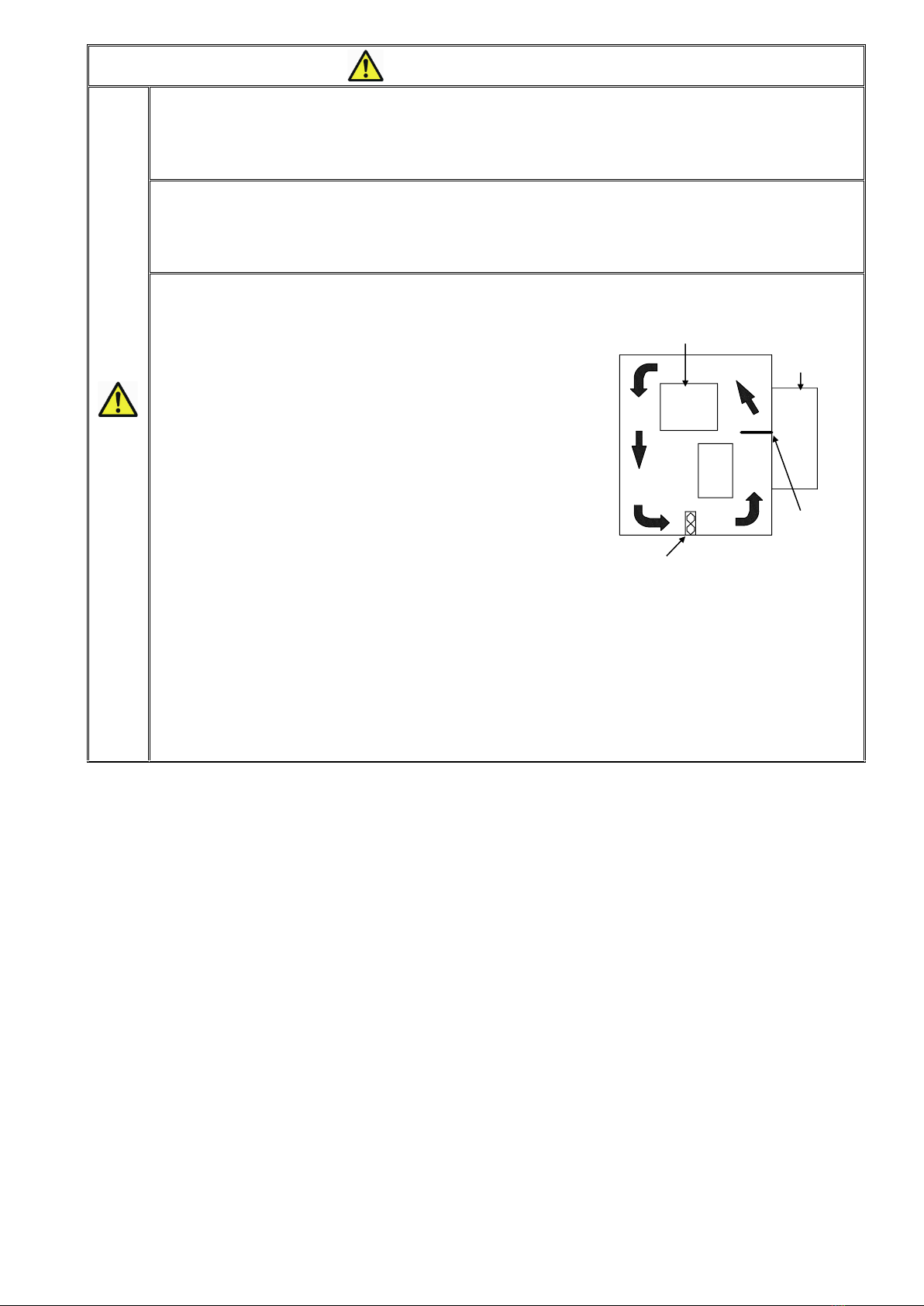
制御盤内で除湿されたドレン水は、以下の方法で蒸発されます。
①制御盤内で除湿され発生したドレン水は、ドレン水蒸発皿に溜まります。
ドレン水蒸発皿内部には、蒸発コイルがあり、温められたドレン水が上部を通過する
盤外空気により気化し、外部へ蒸発します。一方、蒸発コイルが冷たいドレン水により
冷却されるため、冷凍回路の放熱効率が上がります。
Condensate water generated inside an enclosure will evaporates as described below.
Water resulted from dehumidification that took place in an enclosure will pool
in the Evaporation pan. Evaporation coil is equipped in the pan to heat up the water.
Heated water will vaporize by the external air that passes above the pan and goes out.
Meanwhile, the evaporation coil is cooled by cold drain water,
and thus heat radiation rate increases.
②ドレン水蒸発皿で蒸発されないドレン水は、ドレン水蒸発フィンへ流れていきます。
高温のドレン水蒸発フィンにより、さらに温められたドレン水は、フィンを通過する
盤外空気により気化し、外部へ蒸発します。この蒸発の際に、ドレン水が周りから
熱(気化熱)を奪うため、冷凍回路の放熱効率が上がります。
Residue water in the Evaporation pan will flow to the Evaporation fin.
By the high-temperature Evaporation fin and the external air that passes through
the fin, the water vaporizes into the atmosphere. Meanwhile, such evaporation takes
heat away from the surroundings and it brings about higher heat radiation rate.
③ ドレン水蒸発フィンで蒸発されないドレン水は、ドレン水蒸発シートへ給水されます。
コンプレッサの熱とコンデンサの熱で温度上昇した盤外空気により気化し、外部へ蒸発します。
As the final step, the Evaporation sheet absorbs the water not evaporated
in the Evaporation fin to evaporate it by the hot external air heated
by the compressor and the capacitor.
④ 盤内・盤外温湿度:35℃、85%RH 以下で発生するドレン水は 3つの蒸発機構により
蒸発されますが、ノンドレン機能の仕様範囲外で発生するドレン水は、ドレンパイプより
盤外へ排水される構造となっています。
This product is designed to process condensate by the above 3-step evaporation
mechanism on condition that both internal and external temperature
and humidity conditions are under 35 deg. C, 85% RH. Condensate water produced
outside the above range is to be discharged through the drain pipe.
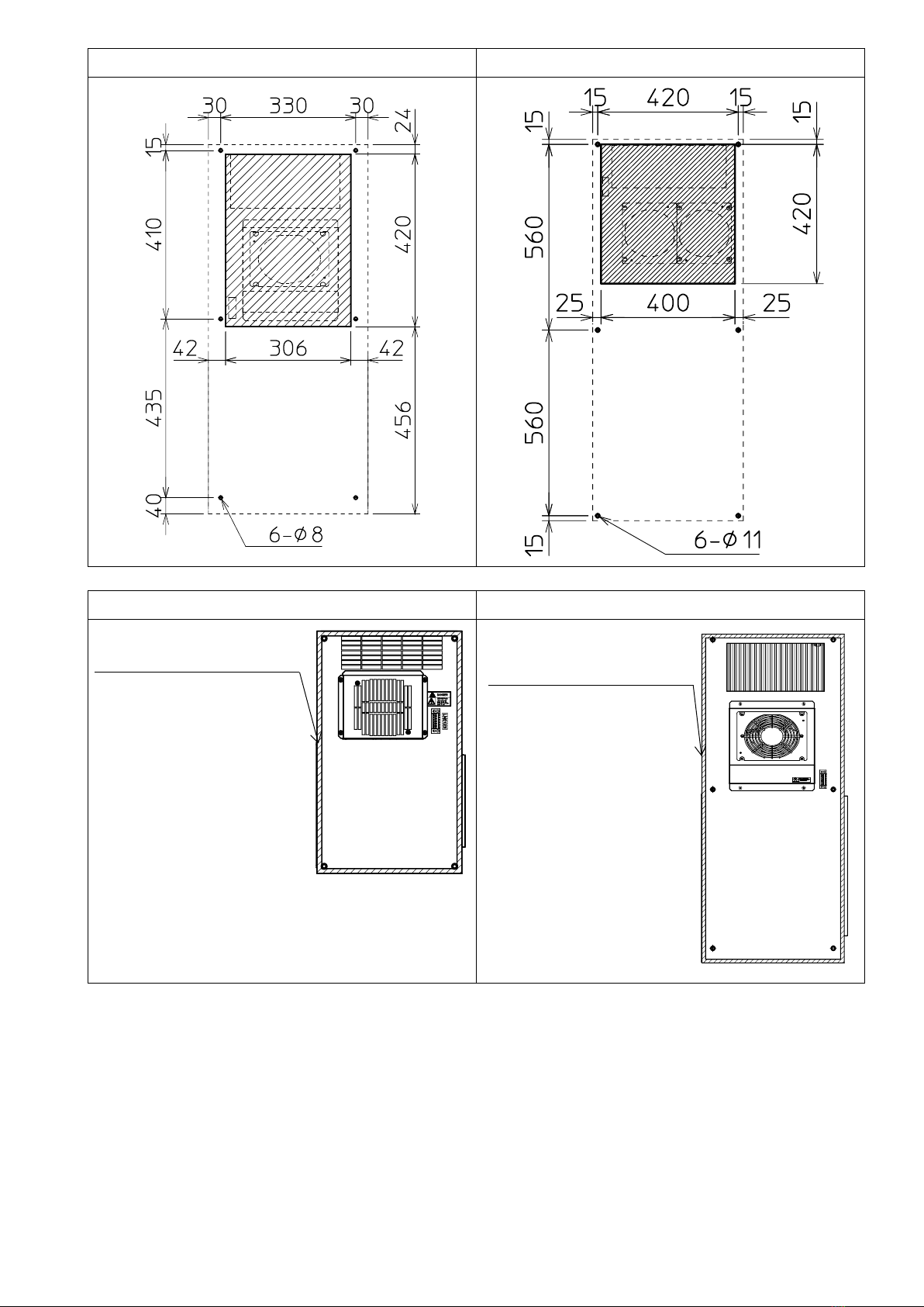
3.制御盤への取付け方法 Mounting
3-1 取付けに関するご注意 Caution
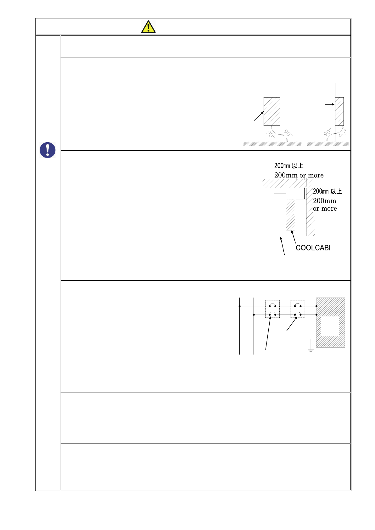
取付穴(M6)に直接回転力が加わるような使い方はしないでください。
→取付穴にはカシメ袋ナットを採用しているため空転する恐れがあります。
In case screws are used for installation instead of the original bolts, put a plate
between the screw and the cap nut so as the direct torque not to be transmitted.
Or, the cap nut may cause slipping.