OHNIYOU GLXCF-016X User manual

OHNIYOU
ENERGY SAVING LIFE
Ceiling Fan With Light
User Manual
GLXCF-016X


Package Includes
1
1.Wood Screw
2.Expansion Screws
Ceiling Fan
Body
Hand-Held
Remote
Check to see that you have received the following parts:
2Hanging Plate
3
5
4
1
1H
2H
4H
R/F
STOP
LOW
MED
HI
LIGHT
ON/OFF
Wiring outlet box and box connectors must be of
type required by the local code. The minimum wire
would be a 3-conductor(2-wire with ground) of the
following size:
Installed Wire Length Wire Size A.W.G
Up to 50 ft 14
50-100 ft 12
NOTE: Place the parts from the loose parts bags in a
small container to keep them from being lost. If any
parts are missing contact your local retailer.
Materials
This manual is designed to make it as easy as possible for you to assemble, install,
operate and maintain your ceiling fan.
⚠WARNING
Before assembling your ceiling fan, refer
your fan (page 10). If you feel you do not
have enough wiring knowledge or experi-
ence, have your fan installed by a
licensed electrician.

Ceiling Fan performance and energy savings rely heavily on the proper
installa�on and use of the ceiling fan . Giving some �ps to ensure
efficient product performance.
Choosing the Appropriate Moun�ng Loca�on
Turn OffWhen Not in the Room
Using the Ceiling Fan Year Round
Energy Efficient Use of Ceiling Fans
2
Electrical and Structural Requirements
Ceiling fans should be installed, or mounted, in the middle of the room and at
ceiling fan to save energy.
Summer Season:
cooler. Select a fan speed that provides a comfortable breeze, lower speeds
consume less energy.
Winter Season: Reverse the motor and operate the ceiling fan at low speed in
warm air near the ceiling down into the occupied space.Remember to adjust
savings could be realized with this simple step!
Your new ceiling fan will require a grounded electrical supply line of 120 volts AC,
60 HZ, 15 Amp Circuit. Electrical code requires use of a fan-rated outlet box to
will be labeled as such and typically supports up to a 70lbs ceiling fan. Fan-Rated
box meet the requirements for the ceiling fan being installed.

3
INSTALL THE MOUNTING BRACKET
⚠WARNING
possible electrical shock, be sure electricity is
Local codes and the ceiling fan must be properly
-
cal shock.
⚠WARNING
personal injury, mount fan to outlet box
(35 Ibs) or less.Use screws supplied with outlet
box. Most outlet boxes commonly used for
fan support and may need to be replaced.
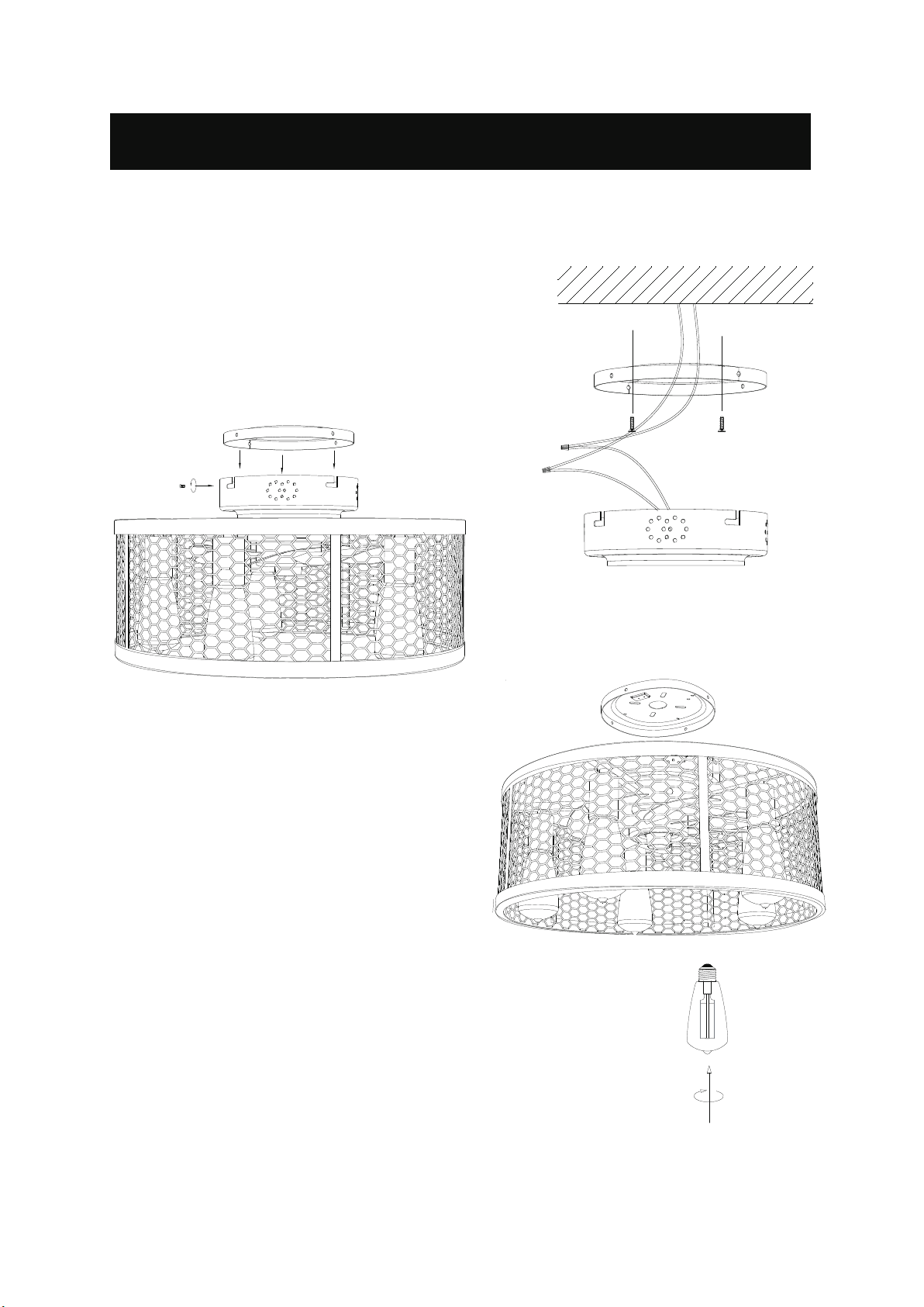
in the ceiling to aid in securing ceiling
bracket with four expansion screws provid-
building structure with four expansion
(If
appearance, you can also only make two
screws.)(Fig.1)
-
ing bracket to the building structure with
four wood screws provided.(Fig.2)
⚠WARNING
Do not operate this fan with a
variable(Rh-eostat) wall controller or
dimmer switch.Doing so could result in
damage to the ceiling fan's remote
control unit.

4
Figure 1,2
Figure 3
Figure 4
How to Install Your Ceiling Fan
1
2
5-E26
ceiling fan body in the side of the
ceiling plate. (Figure 3)
zero line with the power cable. (Figure 2)
1. Pass the wire and through the middle hole of the chassis.
2. Using the wood screws or expansion screws to
(Figure 1)
5. Install light bulbs into sockets by
(Figure 4)

How to Wire Your Ceiling Fan
5
Figure 2
Receiver
Wlack Wire
From Receiver
Black Wire
From Receiver
Black Wire
From Supply
White Wire
From Supply
Green Wire
(Ground)
Green Wire
(Ground) From
Hanger Ball
Household
Supply
Listed Outlet Box
Figure 1
Black
Black
White
White to Motor
Blue to Light
Brown to Motor
Black to Motor
Listed Outlet Box
Green Wire
(Ground)
Green Wire
(Ground) From
Hanger Ball
White
Blue
Brown BLK-ANT
1.Connect green wires from hanger ball to
bare (ground) wire using wire connector.-
Connect black wire from receiver unit
using wire connector. Connect white wire
white supply wire using wire con-nector.
Connect white wire from receiver unit
fan using wire connector supplied with
receiver unit. Connect black wire from
black wire from fan using wire connector
supplied with receiver unit. Connect brown
wire from receiver unit to brown wire from
fan using wire connector supplied with
receiver unit. Lastly, connect blue wire
from receiver unit to the blue fan light wire
using wire connector supplied with receiv-
er unit.(Figure 1)
the receiver into the hanger bracket, taking
care not to pinch the wires and put the
white and green leads to one side and the
black leads towards the other side, the
carefully push leads into the outlet box.
The wires should be spread apart with the
grounded conductor and the equip-
ment-grounding conductor on one side of
the outlet box and the ungrounded
conductor on the other side. (Figure 2)
CAUTION: INCORRECT WIRE CONNECTION WILL DAMAGE THIS RECEIVER.
NOTE: If you feel that you do not have enough electrical wiring knowledge or
experience, have your fan installed by a licensed electrician.

Season Rotation Direction
Summer Counterclockwise
Winter Clockwise
3. To make fan operational, install
AAA/1.5V battery (not included) in
hand-held remote. Store the remote away
from excessive heat or humidly.
4. Remote functions: (Figure 3)
MED Fan Speed Medium
LOW Fan Speed Low
HI Fan Speed High
STOP Fan Stop
LIGHT Light On/Off
1H Fan Stops After 1 Hour
2H Fan Stops After 2 Hour
4H Fan Stops After 4 Hour
R/F Motor Reverse
5. If airflow is desired in the opposite
direction, directly tap the R/F button on
the remote and the fan will stop then
rotate in the opposite clockwise direction.
6
1H
2H
4H
R/F
STOP
LOW
MED
HI
LIGHT
ON/OFF
1H
2H
4H
R/F
STOP
LOW
MED
HI
LIGHT
ON/OFF
Figure 3
Figure 1
How to Operate Your Ceiling Fan
How to Install Your Remote Control
plate using the two provided screws.

7
Trouble Probable Cause Suggested Remedy
1. FAN WILL NOT START
1. Fuse or circuit breaker blown.
2. Loose power line connections
to the fan, or loose switch wire
connections in the switch
housing.
3. Dead battery in remote control.
4. Reversing switch in neutral
position.
1. Check main and branch circuit
fuses or circuit breakers.
2. Check line wire connections to fan
and switch wire connections in the
switch housings.
CAUTION: Make sure main power is
turned off !
3. Replace with new battery.
4. Make sure reversing switch
position is all the way to one side.
2. FAN SOUNDS NOISY
1. Loose screws in motor housing.
2. Wire connectors inside housing
rattling.
3. Motor noise caused by solid
state variable speed control.
1. Check to make sure all screws in
motor housing are snug (do not
overtighten).
2. Check to make sure wire
connectors in switch housing are not
rattling against each other or against
the interior wall of the switch
housing.
CAUTION: Make sure main power is
turned off!
3. Some fan motors are sensitive to
signals from solid-state variable speed
controls. Solid-state control are not
recommended, choose an alternative
control method.
3. FAN WOBBLES
EXCESSIVELY
1. Setscrew in downrod support is
loose.
2. Setscrew in downrod/hanger
ball assembly is loose.
3. Hanger bracket and/or ceiling
outlet box is not securely
fastened.
1. Tighten both setscrews securely in
downrod support.
2. Tighten the setscrew in the
hanging plate assembly.
3. Tighten the hanger bracket screws
to the outlet box, and secure outlet
box.
⚠WARNING
For your own safety turn off power at fuse box or circuit breaker before trouble shooting.
Troubleshoo�ng

Maintenance
1. Periodic cleaning of your new ceiling fan is the only maintenance that is needed.
When cleaning use only a sobrush or lint free cloth to avoid scratching the nish.
Abrasive cleaning agents are not required and should be avoided to prevent
damage to nish.
8
Please feel free to contact us:
Warranty
Dear Customer:
OHNIYOU warrants that this product is free from defects in materials and workmanship
for a period of 1 years from the day of purchase. If the product has been misused,
damaged by accident or in any other way of improper use, this warranty becomes void.
CAUTION
Do not use water to cleaning your ceiling fan. It
could damage the motor or the nish and create the
possibility of electrical shock.
Table of contents
Other OHNIYOU Fan manuals