Oki ML2502 User manual

OKI ML2502 Demo Board
1
ML2502 Demo Board 1999.03.19 ver1.0
INSTRUCTION MANUAL PRELIMINARY version
GENERAL DESCRIPTION
The ML2502 demonstration board is intended as a familiarisation and
demonstration tool to help design-in the ML2502 analog storage recorder LSI.
BOARD LAYOUT
SWITCHES DESCRIPTION
(1) POWER Turn on the POWER and LED (12).
(2) ERASE Erase –enable signal input switch, used together with the
REC1 (6) and/or the REC2 (5).
(3) PLAY2 Input start-playback signal for Phrase 2 to this switch.
(4) PLAY1 Input start-playback signal for Phrase 1 to this switch.
(5) REC2 Input start-recording signal for Phrase 2 to this switch.
(6) REC1 Input start-recording signal for Phrase 1 to this switch.
(2)
ERASE PLAY2 PLAY1 REC2 REC1
MICROPHONE
SPEAKER
SP.GAIN
ML2502
SAM1
SAM2
ON
OFF
+3V
GND
POWER MON
(1)
(12)
(7)
(9)
(10)
(11)
(8)
(3)
(4)
(5)
(6)
OFF
1 2 3 4
R.PHR
P.PHR

OKI ML2502 Demo Board
2
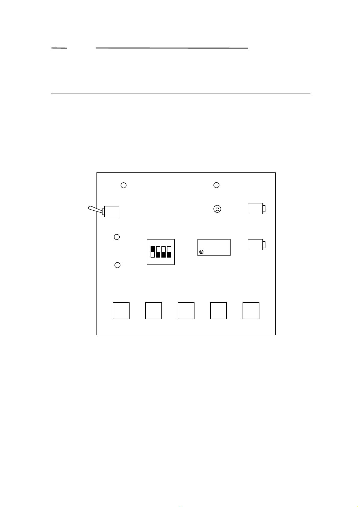
(7) SAM2, SAM1, R.PHR, and P.PHR
SAM2 and SAM1 switches are used to select a sampling frequency.
SAM2 L L H H
SAM1 LHLH
Fsam (kHz) 4.0 5.3 6.4 Disable
The Board Layout shows that SAM2 is “L”and SAM1 is “H”, and
shows 5.3 kHz is set.
P.PHR switch is used to select Dual Phrase Playback-mode or Single
Phrase Playback-mode. The Board Layout shows that P.PHR is “L”,
and shows the Dual Phrase Playback-mode is set.
R.PHR switch is used to select Dual Phrase Recording-mode or Single
Phrase Recording-mode. The Board Layout shows that R.PHR is “L”,
and shows the Dual Phrase Recording-mode is set.
(8) SP.GAIN
When Turn right, the volume is increase.
(9) SPEAKER
Connect the speaker.
(10) MICROPHONE
Connect the microphone.
(11) MON
During recording and playback, turn on the LED.
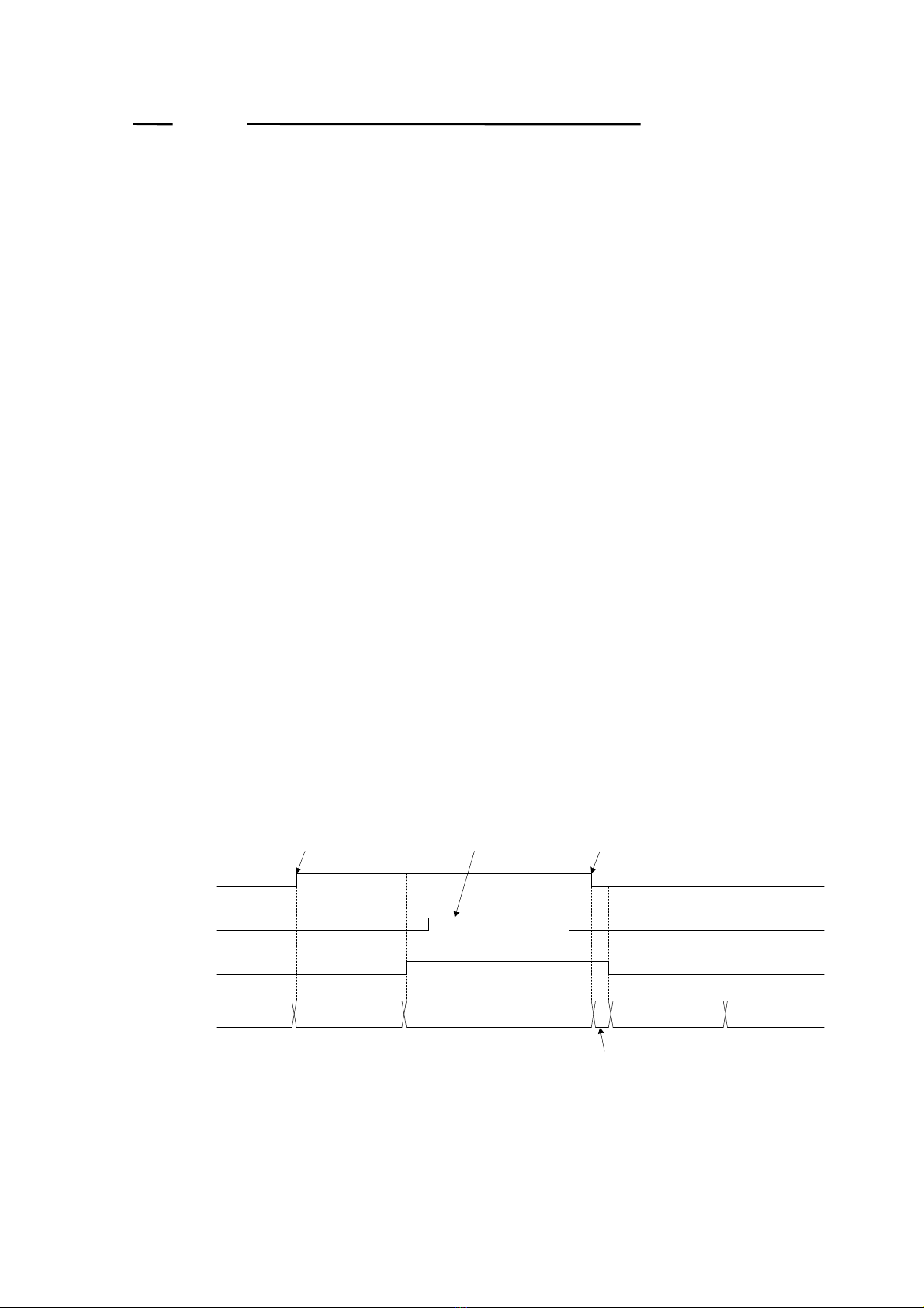
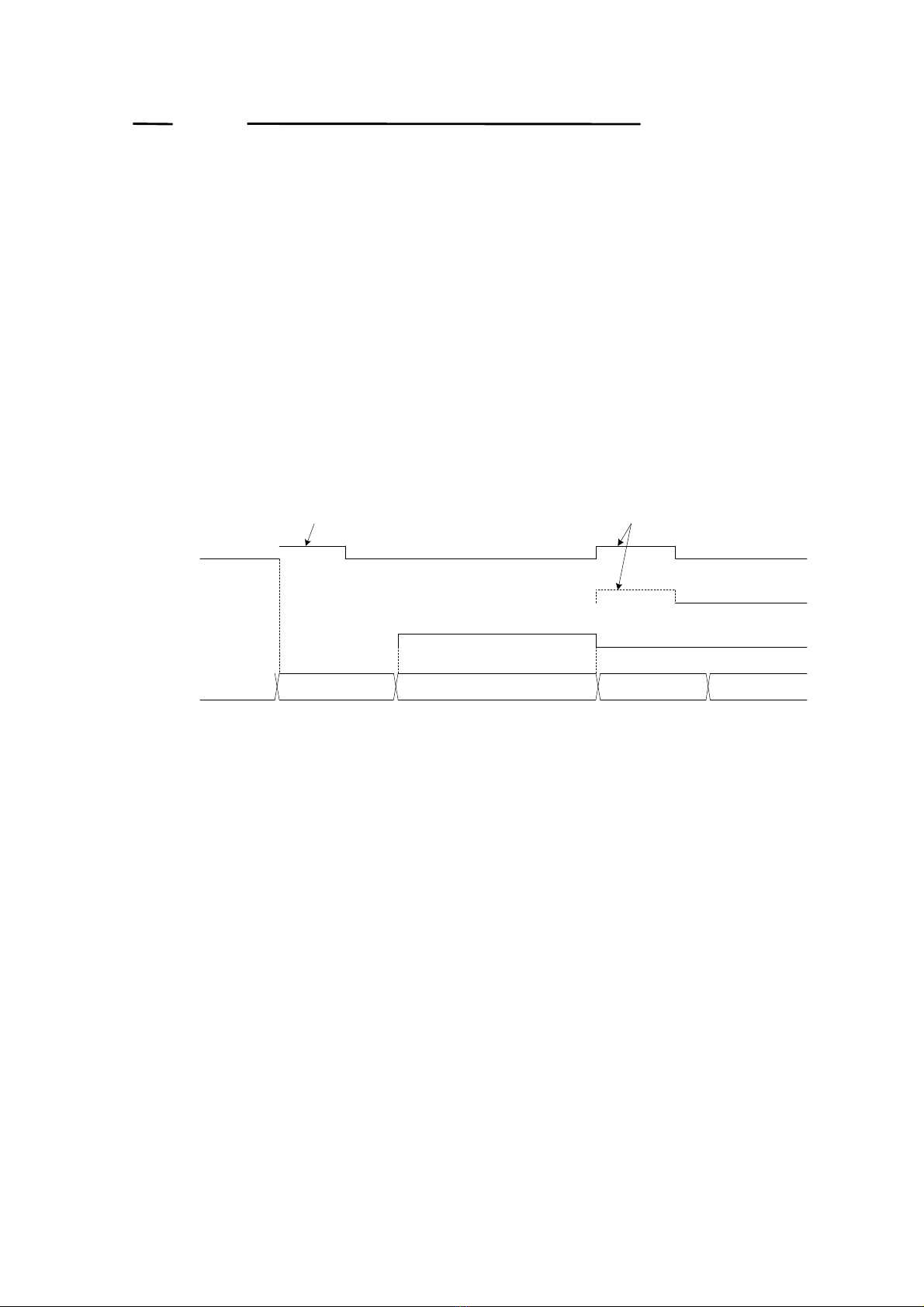
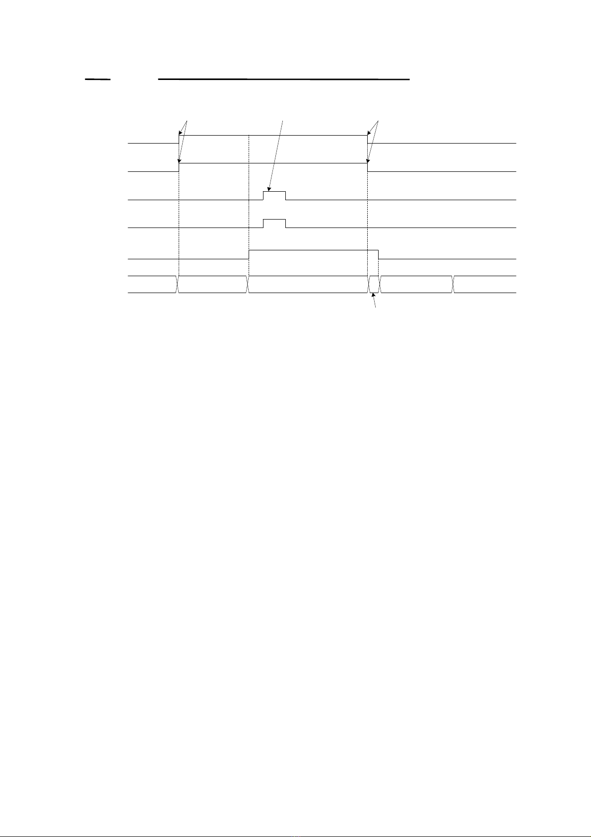
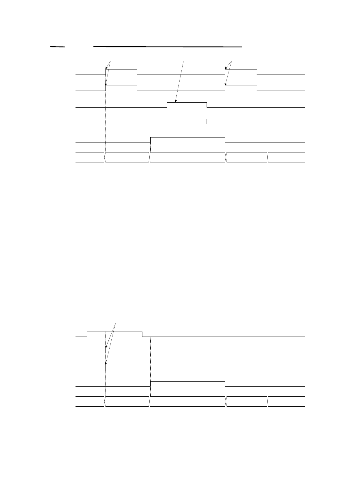
RECORD and PLAYBACK OPERATION
ML2502 has two record/playback modes, Dual-phrase record/playback mode and
Single-phrase record/playback mode. While in Dual-phrase record/playback mode the
total memory space is divided evenly into two areas for 2-phrase record/playback, the
entire memory space is used for one phrase record/playback in Single-phrase
record/playback mode.
In Dual-phrase record/playback mode the first half of the memory, i.e. from the top
address up to the center address, is assigned to Phrase 1, and the second half, i.e. from
the center address to the last address, is assigned to Phrase 2. Record/playback of

OKI ML2502 Demo Board
3
Phrase 1 can be controlled via the REC1 and PLAY1 pins, while Phrase 2 can be
controlled via the REC2 and PLAY2 pins respectively.
In Single-phrase mode record/playback must be performed with the REC1 being
connected to the REC2 pin and the PLAY1 being connected to the PLAY2 pin
respectively.
In both playback modes repetitive playback function for the same phrase is available.
1.
Dual-Phrase Record/Playback Mode
1-1. Phrase 1 Recording Operation
(1) Keep on inputting “H”level to the REC1 pin to power up and start recording
from the top address of the memory. Recording goes on while the REC1 pin
being held “H”level.
(2) The LSI automatically ends recording when the center address has been
reached.
(3) The LSI automatically shifts to low-power consumption mode after recording
ends.
(4) To stop recording for phrase 1 before reaching the center address, bring the
REC1 pin down to “L”level. The LSI automatically shifts to low-power
consumption mode after recording stops.
(5) During recording operation any signal input to other pins than the REC1 is
disregarded.
Note: Re-recording always causes to overwrite the existing recording data for a given
phrase.
Figure 1.1 Timing Chart for Phrase 1 Recording Operation
Start StopInvalid Input
Stopping Process
Power Down Powering Up Recording Power DownPowering Down
MON
REC2
REC1
Status

OKI ML2502 Demo Board
4
1-2.
Phrase 1 Playback Operation
(1) Input a “H”pulse to the PLAY1 pin to power up and start playback from the top
address of the memory.
(2) The LSI automatically ends playback when the last address of the recorded
phrase has been reached.
(3) The LSI automatically shifts to low-power consumption mode after playback
ends.
(4) To stop playback of phrase 1 before reaching the last address, input a “H”pulse
again to the PLAY1 or PLAY2 pin. This will cause the LSI to stop playback and
then automatically shift to low-power consumption mode.
(5) During playback operation signal input to the PLAY1 or PLAY2 pin only is valid,
any other signal input is disregarded
Figure 1.2 Timing Chart for Phrase 1 Playback Operation
Start Pulse Stop Pulse
Power Down Powering Up Playing Back Power DownPowering Down
MON
PLAY2
PLAY1
Status

OKI ML2502 Demo Board
5
1-3. Phrase 1 Erasing Operation
(1) While inputting “H”level to the ERASE pin, input a “H”pulse to the REC1 pin to
start erasing Phrase 1.
(2) After Phrase 1 having been erased, the LSI automatically shifts to power-down
mode for low-power consumption.
Note: Erasing operation cannot be abandoned in the middle once getting started.
Internally, the LSI performs erasing Phrase 1 by recording “Silence”from the
top address to address 250. Therefore, if you attempt to playback the erased
phrase, the playback starts at the top address of the memory and ends at
address 250.
Figure 1.3 Timing Chart for Phrase 1 Erasing Operation
1-4. Phrase 2 Recording Operation
(1) Keep on inputting “H”level to the REC2 pin to power up and start recording from
the top address of the memory. Recording goes on while the REC2 pin being
held “H”level.
(2) The LSI automatically ends recording when the last address of the memory has
been reached.
(3) The LSI automatically shifts to low-power consumption mode after recording
ends.
(4) To stop recording for Phrase 2 before reaching the last address, bring the REC2
pin down to “L”level. The LSI automatically shifts to low-power consumption
mode after recording stops.
(5) During recording operation any signal input to other pins than the REC2 is
disregarded.
Note: Re-recording always causes to overwrite the existing recording data for a given
phrase.
Start Pulse
Power Down Powering Up Erasing Power DownPowering Down
MON
REC1
ERASE
Status

OKI ML2502 Demo Board
6
Figure 1.4 Timing Chart for Phrase 2 Recording Operation
1-5. Phrase 2 Playback Operation
(1) Input a “H”pulse to the PLAY2 pin to power up and start playback from the
center address of the memory.
(2) The LSI automatically ends playback when the last address of the recorded
phrase has been reached.
(3) The LSI automatically shifts to low-power consumption mode after playback
ends.
(4) To stop playback of Phrase 2 before reaching its last address, input a “H”pulse
again to the PLAY1 or PLAY2 pin. This will cause the LSI to stop playback and
then automatically shift to low-power consumption mode.
(5) During playback operation signal input to the PLAY1 or PLAY2 pin only is valid,
any other signal input is disregarded
Figure 1.5 Timing Chart for Phrase 2 Playback Operation
1.6 Phrase 2 Erasing Operation
(1) While inputting “H”level to the ERASE pin, input a “H”pulse to the REC2 pin to
start erasing Phrase 2.
Start StopInvalid Input
Stopping Process
Power Down Powering Up Recording Power DownPowering Down
MON
REC2
REC1
Status
Start Pulse Stop Pulse
Power Down Powering Up Playing Back Power DownPowering Down
MON
PLAY2
PLAY1
Status
Stop

OKI ML2502 Demo Board
7
(2) After Phrase 2 having been erased, the LSI automatically shifts to power-down
mode for low-power consumption.
Note: Erasing operation cannot be abandoned in the middle once getting started.
Internally, the LSI performs erasing Phrase 2 by recording “Silence”from the
center address as far as to address 250. Therefore, if you attempt to playback
the erased phrase, the playback starts at the center address of the memory and
ends at address 250.
Figure 1.6 Timing Chart for Phrase 2 Erasing Operation
2. Single-phrase Record/Playback Mode
2-1. Recording Operation
(1) In this mode the REC1 has to be connected with the REC2 pin.
Keep on inputting “H”level to the REC1 and the REC2 pin to power up and start
recording from the top address of the memory. Recording goes on while the
REC1 and the REC2 pin being held at “H”level.
(2) The LSI automatically ends recording when the last address of the memory has
been reached.
(3) The LSI automatically shifts to low-power consumption mode after recording
ends.
(4) To stop recording before reaching the last address, bring the REC1 and the REC2
pin down to “L”level. The LSI automatically shifts to low-power consumption
mode after recording stops.
(5) During recording operation any signal input to other pins than the REC1 and the
REC2 is disregarded.
Note: Re-recording always causes to overwrite the existing recording data for a given
phrase.
Start Pulse
Power Down Powering Up Erasing Power DownPowering Down
MON
REC2
ERASE
Status

OKI ML2502 Demo Board
8
Figure 2.1 Timing Chart for Single-phrase Recording Operati
on
2-2. Playing Back Operation
(1) Input “H”pulses to the PLAY1 and the PLAY2 pins simultaneously to power up
and start playback from the top address of the memory.
(2) The LSI automatically ends playback when the last address of the recorded
phrase has been reached.
(3) The LSI automatically shifts to low-power consumption mode after playback
ends.
(4) To stop playback of the phrase before reaching its last address, input “H”pulses
again to the PLAY1 and the PLAY2 pins simultaneously. This will cause the
LSI to stop playback and then automatically shift to low-power consumption
mode.
(5) During playback operation signal input to the PLAY1 or PLAY2 pin only is valid,
any other signal input is disregarded.
Start StopInvalid Input
Stopping Process
Power Down Powering Up Recording Power DownPowering Down
MON
REC2
REC1
Status
PLAY2
PLAY1

OKI ML2502 Demo Board
9
Figure 2.2 Timing Chart for Single-phrase Playback Operation
2-3. Erasing the Phrase 2
(1) While inputting “H”level to the ERASE pin, input “H”pulses to the REC1 and
REC2 pins simultaneously to start erasing the phrase.
(2) After the phrase having been erased, the LSI automatically shifts to power-down
mode for low-power consumption.
Note: Erasing operation cannot be abandoned in the middle once getting started.
Internally, the LSI performs erasing by recording “Silence”from the top
address as far as to address 250. Therefore, if you attempt to playback the
erased phrase, the playback starts at the top address of the memory and ends
at address 250.
Figure 2.3 Timing Chart for Single-phrase Erasing Operation.
Start Pulse Stop PulseInvalid Input
Power Down Powering Up Playing Back Power DownPowering Down
MON
REC2
REC1
Status
PLAY2
PLAY1
Start Pulse
Power Down Powering Up Erasing Power DownPowering Down
MON
REC1
ERASE
Status
REC2

OKI ML2502 Demo Board
10
3. Repeating Playback Operation
(1) To repeat playback of the same phrase, keep on inputting “H”level to the PLAY1
or PLAY2 pin. “H”level input to the PLAY1 or PLAY2 causes the LSI to power
up and start playback.
(2) The LSI automatically restarts playback when the last address of the phrase has
been reached.
(3) When the playback reaches to the last address of the phrase, with the PLAY1 or
PLAY2 pin being held “L”level, the LSI automatically ends playback.
(4) The LSI automatically powers down after playback ends.
(5) To stop playback before repetitive playback session ends, bring the PLAY1 or
PLAY2 pin down to “L”level once, and then re-input a “H”pulse to the PLAY1 or
PLAY2 pin. The LSI automatically shifts to low-power consumption mode after
playback stops.
Figure 3.1 Timing Chart for Repetitive Playback Operation
Start Pulse Stop Pulse
Power Down Powering Up Playing Back Power DownPowering Down
MON
PLAY2
PLAY1
Status Interval Playing Back
End Playing Resume Plaing

OKI ML2502 Demo Board
11
CIRCUIT DIAGRAM
5.1kΩ
DGND
0.1µF
100µF
1001
AGND
AVDD
DVDD
REC1
REC2
PLAY1
PLAY2
ERASE
MIN
DGND
LOUT
LIN
MOUT
0.1µF
SAM1
TEST
SPOUT-
AGND
SPIN
AOUT
MON
SAM2
ROSC
ML2502MB
DVDD
51pF
200kΩ
0.47µF
10kΩ
From Microphone
0.47µF
2
3
1
HSJ-
0785
3
4
5
6
8
11
10
9
1nF
20kΩ
0.47µF
50kΩ
DGND
To Speaker
2
3
1
HSJ-
0785
VR1
5.1kΩ
DGND
30kΩ
DGND
DGND
DVDD
DIP
SW
SPOUT+
26
17
19
29
28
27
21
20
24
14
18
2
12
13
0.1µF
DVDD
AVDD
100kΩ
100kΩ
7
25
µPC2933NF
0.1µF
22µF
2
3
1
DIP
SW
Table of contents
Other Oki Motherboard manuals