Oldfield Treco 63 User manual

GARDEN SHEDS
63, 65, 67, 69, 83, 85, 87, 89, 103, 105, 107 & 109
TRECO SHEDS ARE MANUFACTURED TO COMPLY WITH ALL AUSTRALIAN STANDARDS
8’
6’
10’
Please visit the manuals section at our website for any updates or corrections to this manual
www.oldfields.com.au/treco/index.htm X16 - 11/06

BEFORE YOU START, IT IS IMPORTANT THAT YOU READ THE FOLLOWING INSTRUCTIONS.
• When selecting a site, choose an area that is firm and level yet allows drainage away from the site.
• Although this shed when installed according to instructions, is designed to withstand greater wind loads than
other conventional sheds, do not install it in areas subject to high winds or erect on a windy day. Any
building left partially constructed may be seriously damaged if left in this state. It is your responsibility to safely
and securely anchor the shed, having regard to the windiest conditions in the area. The shed could possibly blow
away causing damage and possible injury if not properly attached to the ground foundation.
• Do not backfill against the walls or base of the shed as this will cause corrosion and void the warranty.
• The prevention of condensation inside the shed will assist in keeping the contents dry as well as minimising any
possible corrosion of the shed itself, the following hints may prove useful.
There is always dampness in soil, and this may rise into the shed if there is no barrier. A heavy duty polythene
sheet may be placed under the concrete slab to prevent evaporation into the shed, (illustrated in Step A).
Seal the space between the bottom frame and the concrete slab with a mastic (except at the front corners) which
does not completely dry out. The front corners are not sealed to enable drainage out of the ends of the front base
rail.
If condensation still presents a problem, panels of polystyrene (5cm thick) may be glued to the interior of the roof
between the supports. Use a glue that is resistant to moisture and temperature. This has the further advantage
of keeping your shed cooler on hot summer days.
• Check the labels on the packs to ensure you have the model shed you ordered and the correct number of
packs.
• You will need a few tools, and some extra equipment which may prove useful to make assembly faster and
easier (these are indicated in the section HOW TO READ THIS MANUAL). All holes for screws are predrilled. A
power screw driver or cordless drill equipped with a magnetic Philips tip will hasten assembly. Take care not to
over-tighten self-tapping screws.
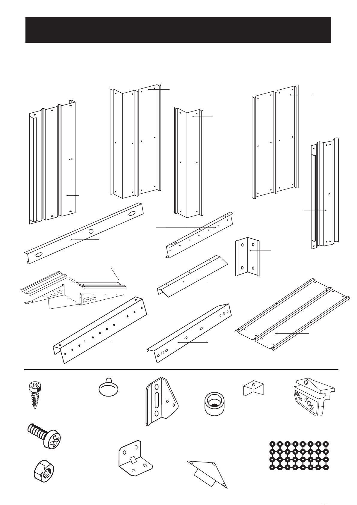
• Sort, separate and identify all parts and hardware before construction. Check against the illustrations shown at
the top of each step illustrated in this manual. Pieces are labelled except for panels, check with the labelling on
the diagrams shown. Not all drawings are to scale since some have been enlarged to enable easier viewing in
comparison to other pieces.
• Since this manual is used to instruct installation of varying sizes of shed, Labelling of Parts in the diagrams has
been simplified as follows:
All the frame work components have the same system of part numbers but indicate different lengths, these part
numbers are stamped into the component.
e.g. Roof Beams 9 foot length = P9, 7 foot length = P7, 5 foot length = P5, 3 foot length = P3
Therefore, in the diagrams the Roof Beam is labelled P.
e.g. Rear Midwall Brace 10 foot length = G1A, 6 foot length = G6A
Therefore, in the diagrams the Rear Midwall Brace is labelled G.A.
• Most helpful of all, get a friend or family member to help you.
When you first unpack your shed, construction may look complicated ... but it really isn’t. Simply follow the
illustrated instructions and your Garden Shed will be erected quickly and accurately.
MODEL (feet) (millimetres) (inches) (millimetres) (feet) (millimetres)
63 6’ x 3’ 1830 x 920 75 1930 5’7” x 2’9” 1710 x 820
65 6’ x 5’ 1830 x 1540 75 1930 5’7” x 4’9” 1710 x 1440
67 6’ x 7’ 1830 x 2160 75 1930 5’7” x 6’9” 1710 x 2060
69 6’ x 9’ 1830 x 2780 75 1930 5’7” x 8’9” 1710 x 2680
83 8’ x 3’ 2450 x 920 77 1980 7’7” x 2’9” 2330 x 820
85 8’ x 5’ 2450 x 1540 77 1980 7’7” x 4’9” 2330 x 1440
87 8’ x 7’ 2450 x 2160 77 1980 7’7” x 6’9” 2330 x 2060
89 8’ x 9’ 2450 x 2780 77 1980 7’7” x 8’9” 2330 x 2680
103 10’ x 3’ 3070 x 920 79 2030 9’8” x 2’9” 2950 x 820
105 10’ x 5’ 3077 x 1540 79 2030 9’8” x 4’9” 2950 x 1440
107 10’ x 7’ 3077 x 2160 79 2030 9’8” x 6’9” 2950 x 2060
109 10’ x 9’ 3077 x 2780 79 2030 9’8” x 8’9” 2950 x 2680
1
THIS MANUAL WILL BE USED FOR THE FOLLOWING GARDEN SHED MODEL NUMBERS
APPROX. ROOF DIMENSIONS OVERALL HEIGHT APPROX. BASE DIMENSIONS
INSTALLATION ADVICE

Note: All the tools listed are required for the erection of the garden shed.
These tools should be at hand before starting work.
1. Step ladder
2. Spanner
3. Tape measure
4. Cordless power screw driver or power drill
5. Dyna bolts (not supplied) 6.5mm x 36mm recommended
6. Multi grips
7. Philips-head screw driver bit (P2)
6
2
4
3
5
1
7
TOOLS REQUIRED
2
SORT, SEPERATE AND IDENTIFY ALL PARTS AND
HARDWARE BEFORE CONSTRUCTION.
CHECK AGAINST THE PART ILLUSTRATIONS
SHOWN ON PAGES 5 AND 6.

IMPORTANT INSTRUCTIONS
STEP A - FOUNDATION
A solid foundation is required. Construct a level concrete slab, reinforced with 5mm diameter x 200mm
grid wire mesh. Allow 7 days minimum curing time before erecting your shed. You may select other
methods of constructing a solid base using paving slabs or timber if desired, but please ensure it is
level and provides secure anchorage.
1 BASE RAILS
Two corner gussets (X20) are used to attach the base rails in the rear corners only. Ensure that the base is
square.
2 CORNER PANELS
Bend the corner panels carefully to 90° angle. Ensure that the longer side of the panel is pointing along the
width (i.e. front / back) side of your shed.
3 TOP RAILS / DOOR GLIDES
Ensure wheels face inside of shed.
4 MIDWALL BRACES
Use corner gussets (X20) on the back corners only.
5 WALL PANELS
Assemble all panels shown. No wall panels are used on the front of the shed (door side).
6 GABLES
Assemble the roof beam brackets (X15A for all 10' Models), onto the gables in the positions and direction
shown.
7 ROOFBEAMS
Position 2 roof beam sections 'P' back to back and connect. Ensure roof panel holes are parallel.
8 ROOF END PANELS
Fasten the roof end panels to the gables. Then fasten them to the roof beam using the self tapping screws
and plastic washers. Fasten in order shown in diagram.
9 ROOF PANELS
Fasten the roof panels ensuring that you work down along one side of the roof. Then, starting at the other
side, fix one roof panel, followed by a ridge capping, continuing until the roof is complete. Be sure to use the
plastic washers.
10 ROOF EDGE TRIM AND ACCESSORIES
Connect the roof accessories to cover sharp edges.
11 ANCHORING
Your shed must be anchored down. Ensure that your shed is square. Using a masonry drill bit (6.5mm
diameter), drill through the holes provided in the base rails. Anchor your shed using 6.5mm diameter x 40mm
long dyna bolts. Before fixing doors.
NOTE: These bolts are not supplied with the hardware kit.
12 DOORS
Both the door panels are identical - it is the assembly that makes them left and right handed. Lay the doors
on the ground so that the handle position holes are facing each other (i.e. at the centre, as they would be
when assembled). Note that the ribbing on the doors faces towards the inside of the shed (i.e. they are the
opposite of the wall panels). Use the three holes on the door glides to adjust the door alignment.
3

PARTS LIST
Qty Qty Qty
Corner panel F 2 4 4
Half Corner panel F6 2 - -
Door Brace W 4 4 4
Door Fascia J 1 1 1
Door Jamb L 2 2 2
Door panel V 2 2 2
Entry/Exit Ramp E 2 2 2
Front Base Zed D 2 2 2
Front Mid-Wall brace M 2 2 2
Hardware:
Kit Bag X 1 1 1
Corner Gusset X20 4 4 4
Door Glide X6 4 4 4
Door Glide Wheel X9 4 4 4
Door handle TR01031Q 2 2 2
Door Spacer X17 4 4 4
Door Track Bracket X26 NA NA NA
Owner’s Manual X16 1 1 1
Ridge End Cap X10 2 2 2
Roof Corner Cap X8 4 4 4
Roof Washer Sheet X11 4 4 4
10’ Roof Beam Bracket X15A - - 4
Self Tapping Screws X12 400 400 400
3/16” Dia. Bolts & Nuts X13 150 150 150
Left-hand Gable N 2 2 2
Roof End Panel RQ 4 4 4
Right-hand Gable O 2 2 2
Roof Panel S 4 2 4
Wall panel K 5 4 7
Door Track/Rear Top Rail I 2 2 2
Front Base Rail C 1 1 1
Rear Base Rail A 1 1 1
Rear Mid-Wall Brace GA 1 1 1
Ridge Cover End Capping U3 2 2 2
Ridge Cover Inter Capping U2 - - -
Roof Beam P 2 2 4
Roof Edge Trim T 2 2 2
Side Base Rail B 2 2 2
Side Mid-Wall Brace HA 2 2 2
Side Top Rail H 2 2 2
PART 6' 8' 10'
4
Variable
Variable
Variable
Variable
Note: Part codes may be
followed with a number
eg: H7, B7. The numbers
refer to width and depth
of shed. Therefore a 87
shed will have C8 and B7.

63, 65, 67, 69, 83, 85, 87, 89, 103, 105, 107 & 109
5
Refer to parts listing for 6', 8' & 10' model shed labels, sizes and quantities.
PARTS - Pack 'A'
K
Wall Panel
F
Corner Panel
F6
Corner Panel
63, 65,
67 & 69
models
only
X 12
SCREW
3/16” x 3/8”
X 13B
NUT 3/16”
X 13A
BOLT 3/16” x 3/8”
X11
Washers
S
Roof Sheet
E
Entry / Exit Ramp
L
Door
Jamb
M
Front Mid-
Wall Brace
X26
Door Track
Bracket
W
Door Brace
D1
Front Base Z
X15A
Gable Bracket
10ft sheds only
J
Door Fascia
V
Door Panel
O
RQ
N
Left/Right
Gables
RQ
Roof End
X9
Door Glide
Wheel TR01031Q
Door
Handle
X8
Roof Corner
Cap
X17
Door
Spacer
X6
Door
Glide
X20
Corner
Gusset

6
6
P
Roof Beam
A
Rear Base Rail
B
Side Base Rail
T
Roof Edge Trim
U2
Ridge Cover Intermediate
Roof Capping
U3
Ridge Cover
End Roof Capping
GA
Rear Mid-Wall Brace
I
Front/Rear Top Rail
63, 65, 67, 69, 83, 85, 87, 89, 103, 105, 107 & 109
Refer to parts listing for 6', 8' & 10' model shed labels, sizes and quantities.
C
Front Base Rail
PARTS - Pack 'B'
H
Side Top Rail
HA
Side Mid-Wall Brace

Door
100mm
C
D
E
D
X
Door
Y
E
100mm
S 7 14 21 28
M 1 8 15 22 29
T 2 9 16 23 30
W 3 10 17 24
T 4 11 18 25
F 5 12 19 26
S 6 13 20 27
CALENDAR
FOUNDATIONS
Add 100mm
to roof size
depth
Add 100mm
to roof size
width
Add 7 days
for concrete
to cure
7

X6
X9
I
Door Glide (x4)
X9
X6
Inside
of Shed
Outside
of Shed
INSIDE
OF SHED
X9
X6
I
X12
X13A
X26
X13B
O
N
I
X6 + X9
Door Glide
1. Insert 'X9' into 'X6' as shown and repeat 4
times to create 4 x 'Door Glide'.
2. Insert 4 x 'Door Glide' into part 'I' as shown.
Front Gable
PRE-ASSEMBLE FRONT AND BACK GABLES, ROOF BEAMS AND FRONT
BASE RAIL - BEFORE ERECTING SHED.
STEP 1
8
Note: Do not fix
'X12' to end holes
Outside of shed
'I' has holes for
wall panel
'I' has no holes
facing inside of shed

X13A
X13B
Back Gable
Only tighten with 1 x
'X13A + X13B' for all
6'and 8' shed models
Tighten with 2 x
'X13A + X13B' for all
10' shed models.
I
O
N
STEP 1 - Continued
9
Screw Gables to top rail as shown for front gable.
Note: There is no X26 brackets for back gable assembly.

STEP 1 - Continued
P
X13A
Quantity of part 'P' = 2 for 6' and 8' shed models.
Join 2 x 'P' to create centre roof beam.
Quantity of part 'P' = 4 for 10' shed models.
Join 2 x 'P' for centre roof beam
Leave 2 x 'P' = 'P singles' for left and right roof beams.
Roof Beam
P
X13B
Note: Top
holes for roof
fixing must be
parallel
Note: X15A Gable Brackets
for 10' Wide Shed only
10
X13
X13B
Note: Leave
the three slots
at each end
empty

1111
E
E
D
D
B
B
A
C
A
B
X20
X20
X20
B
D
C
BASE FRAME ASSEMBLY
Front Base Rail
Side Base Rails
Back Base Rail
Corner Gussets
E
E
C
D
X12
D
X12
X12
STEP 2

Note: All corner panels must be screwed
to base rails according to the order and
position in the diagrams shown.
1
2 3 4
F1
2
F6
Corners 'F' and half corners 'F6' supplied with 45° degree bend. With a supporter,
bend the panels 90° degrees manually. (Do not over bend).
F
F
Supporter
Use 'F6' (front half corner panel)
for 6' shed models only.
F6
F6
Supporter
INSTALLING CORNER PANELS, MID & TOP WALL BRACES AND WALL PANELS
Corner Panels
A
B
F or F6
B
1. Fix corner panel
with short side of
corner panel to
side base rail 'B'.
X20
X20
1
4
3
2
Use 'F' for all 8' and 10' shed models.
STEP 3
12

Corner Panels
Mid-Wall Brace
Top-Wall Brace
1Fix top rail 'H' and mid-wall rail
'HA' to front corner 'F'(or 'F6')
to stabilise front corner before
fitting back corners.
F or F6
H
H = Top Rail
Curved side of H rail
for roof fixing, flat side
for wall fixing
HA
HA = Midwall Rail
H
HA
B
A
B
X20
X20
Note: brace mid-
wall rail 'HA' and
top rail 'H' against
ground surface
to stabilise front
corner panel.
HA
2Fix back corner panel 'F' to back side of shed with
short side of corner panel 'F' to side base rail 'B' and
use 4 x 'X12' to fix to base rail 'B' and 'A'. Follow
'X12' fixing order diagrams.
H
1
4
3
2
X12
X12
A
B
B
F
STEP 3 - Continued
13
F or F6

H
K
HA
K
K
F or F6
F
14
3Lift mid & top wall (braces) 'H' & 'HA' into
position and fix corner panel 'F' to 'H' &
'HA' rails with 2 x 'X12'.
Wall Panels
4Fix wall sheet 'K' to the side of shed overlapping
the back corner sheet. Continue to fix wall
sheets 'K' towards front of shed with the last
sheet underlapping the front corner panel.
REPEAT
STEPS 1 - 3
FOR OPPOSITE
SIDE OF SHED
HA
H
F or F6
F
2
1
A
B
B
A
B
B
K
X12
X12
STEP 3 - Continued

15
INSTALLING ROOF GABLES, FRONT & BACK MID-WALL RAILS & DOOR JAMBS
Corner Gussets
Gables
Back Mid-Wall Rail
1. Fix with 'X12's the front and back gables to the corner
panels 'F'. Fix with 'X12's through the top rail 'H' and
gable for each corner.
2. Fix back mid-wall rail 'GA' to each back corner panel 'F'.
3. Fix 2 x 'X20' corner gussets (brackets) to each back side
mid-wall rail 'HA' with back mid-wall rail 'GA'.
GA
X20
GA
H
HA
Front
Gable
Back
Gable
Note: 'X20'
corner brackets
are only fixed to
back base rail
and back mid-
wall frames.
HA
H
Door Glide 3
2
1
321
321
321
3
2
1
3
2
1
STEP 4
4
4
4
4

L
LM
16
Door Jambs
HA
M
Front Mid-Wall Rails
Back Wall Panels
4. Continue to fix remaining wall sheets 'K' to back of shed.
5. Fix door jambs 'L' under the front corner panel 'F' and fix with screws to the front
top rail 'I' and base rail 'C' (repeat for both door sides).
6. Fix 2 x 'M' front mid-wall rails to front side mid-
wall rails 'HA' as shown. Fix with screws in front
corner panel F or F6 and door jambs 'L'.
HA
M
K
K
K
F or F6
L
'L' fitted under
'F' or 'F6'
Front
Gable
Back Gable
H
H
HA GA
X12
X12
X12
STEP 4 - Continued

17
INSTALLING CENTRE ROOF BEAM - ALL MODELS
Centre Roof Beam
Fix pre-assembled centre roof beam 'P' to
top of back and front gables and secure
with 2 x 'X13A + X13B' for each gable.
X13B
X13A
Centre Roof
Beam 'P'
H
Front
Gable
Back
Gable
Door Glide
H
REPEAT
FOR FRONT
GABLE
LL
Back
Gable
STEP 5

Left & Right Roof Beam
Quantity of part 'P' = 4 for 10' shed models only.
Use 2 x remaining 'P singles' for left and right roof beams. Follow diagrams as
shown.
1 x 'P' single
(right roof beam)
10' models only.
1 x 'P' single
(left roof beam)
10' models only.
INSTALLING LEFT AND RIGHT ROOF BEAMS
X15A
P
X13A
X13B
X15A1
P
X13B
X13A
STEP 5.1 FOR 10' SHED MODELS ONLY
18

INSTALLING ROOF END PANELS, ROOF PANELS, ROOF CAPPING AND TRIMS
Roof End Caps
All fasteners on roof need washers 'X11' attached.
Fix roof ends 'RQ' with bolts & washers from top of appex
to the side wall, as shown in diagram.
Fix screws & washers to roof beam(s) 'P' and side rails 'H'.
X13A
X11
X13B
Panel to
Panel
3/16"
Nut & Bolt
X12
X11
Panel to
Frame
P
RQ
RQ
RQ
RQ
P
P
X12
P
X12
X11
X13B
X13A
X13B
X13A
X12
H
H
Note: Please seal
all un-used pre-
punched holes in
the roof using 3/16"
bolts and nuts
'X13A + X13B'
and plastic washers
'X11' supplied.
STEP 6
19
This manual suits for next models
11
Table of contents
Popular Lawn And Garden Equipment manuals by other brands

ABSCO SHEDS
ABSCO SHEDS 30152SK Assembly & instruction manual

Davaon
Davaon Pro 46cm Chopping Axe USER and CARE INSTRUCTIONS

ClearSpan
ClearSpan Sunblocker Pro Shade instruction manual

Stihl
Stihl FS 94 R instruction manual

Costway
Costway TL35142 user manual

Factoryfurniture
Factoryfurniture SCROLL Operation & maintenance manual