OLIJU IMTP 2.2 M-RS Manual

Motor Pump Inverter
Type
IMTP 2.2 M-RS
ITTP 2.2 M-RS
ITTP 4 M/W-RS
ITTP 5.5 M/W-RS
ITTP 7.5 W-RS
ENG - Operation and maintenance handbook

2 IMTP2.2-ITTP2.2/4/5.5/7.5 ENG
INDEX
1. SPECIFICATIONS....................................................................................................................... 3
2. WORKINGOPERATIONS........................................................................................................... 3
2.1STRUCTUREOFAFREQUENCYCONVERTER.............................................................. 3
3. WORKINGCONDITIONS.......................................................................................................... 4
4. WARNINGSANDRISKS........................................................................................................... 4
5.ASSEMBLINGANDINSTALLATION............................................................................................ 5
5.1Fixingmeasures................................................................................................................ 5
5.2 Pumphydraulicconnection............................................................................................... 6
5.3 Electricconnections.......................................................................................................... 6
5.4Motor-pumpsphasesconnection....................................................................................... 6
5.5 ElectricconnectiontoLineandMotor................................................................................ 7
5.6 Pressuretransducerconnection,ondifferenttypes........................................................... 8
5.7Connectionsontheelectronicboard................................................................................. 9
6. STARTINGANDPROGRAMMING.......................................................................................... 12
6.1FirstInverterUsingÐSelfRegulationprocedure............................................................. 12
6.2UserÕscheckafterInvertersetting................................................................................... 12
6.3 ProgrammingFunctions.................................................................................................. 13
6.4 Alarms............................................................................................................................. 16
6.5GroupFunctioning-datatransmissionviaserialbusRS485........................................... 16
6.6Replacingthebattery....................................................................................................... 17
7. SOLUTIONOFTHEMOSTCOMMONPROBLEMS................................................................ 17
8. GUARANTEE........................................................................................................................... 18
9. DICHIARAZIONEDICONFORMITAÕ/DECLARATION OF CONFORMITY............................. 19

3 IMTP2.2-ITTP2.2/4/5.5/7.5 ENG
1. SPECIFICATIONS
With this manual, we would like to give you the most important information about the correct use and
maintenanceoftheinverter.
Thedevicesdescribedinthismanualare:
§IMTP2.2M-RS:Single-phaseInverterformotorpump,max2.2kW(3Hp)
§ITTP2.2M-RS:Three-phaseInverterformotorpump,max2.2kW(3Hp)
§ITTP4.0M/W-RS:Three-phaseInverterformotorpump,max4kW(5.5Hp)
§ITTP5.5M/W-RS: Three-phaseInverterformotorpump,max5.5kW(7.5Hp)
§ITTP7.5W-RS: Three-phaseInverterformotorpump,max7.5kW(10Hp)
Thisinvertersaredevicesspeciallydesignedforpumpmotorcontrol,thankstoaperfectfeed-backpressure:it
assures a good energy saving and it has many programmable functions, that are not in the other common
directlysuppliedmotorpumps.
Thefollowinginstructionsandrulesaboutthestandardconfigurationareasfollows.
IfyourequiretechnicalassistanceregardingspecificpartsatServiceSalespleasedospecifytheexactinitials
ofthemodel,followedbytheserialnumberofthemodel.
2. WORKING OPERATIONS
ThisPumpÐInvertersystemismadeupbyacentrifugalpump,thatismovedbyanasynchronousmotor.This
system has to keep the pressure steady, independently from the flow (consistent with the maximum load
applicabletothemotor,otherwisethemaximumcurrentabsorption).
Theoutputpressureismonitoredbyapressuretransducer,with4-20mAor0-5Voutput.Thecontrollogicworks
withanoutputof5or15V(switchable),thatsuppliesthepressuretransducer.
MINIMUM FLOW WORKING PROTECTION: to prevent a closed delivery working, the control logic read the
motorÕs working point condition; if this point is under a setting value, the system switches off the pump, and
appearsonthedisplayÒMinimumFlowÓ.Attheendofthiscondition,thesystemrestartsitsnormaloperation.
Thepumpcurveisdetectedbytheinitialself-regulationcheck.
DRYWORKINGPROTECTION:Toavoidthatthepumpcancontinuetooperateafteraprobleminabsenceof
suction/intakewater,thesystemreadsomeinformationoftheelectricmotor,inatimeof40seconds,andwhen
theygobelowaminimum,turnoffthepumpandshowtherelativesignalofalarmÒDryWorkingÓ.Theinverter
triesN¡5consecutivere-startinthiscondition,onespaced15minutesofeachother.Afterthefifthconsecutive
fault,switchontheledAlarmandthere-startmustbemanuallydo,pressingSTOPfollowedbySTART.
The motor pump electric protection is controlled by the limitation of the current absorption (programmable).
When the current protection is on, an alarm appears on display. When the condition disappear, the system
restartwiththenormalfunctioning.
2.1 STRUCTURE OF A FREQUENCY CONVERTER
Figure 1: structure of a frequency converter
d.c. Directcurrent
Rec Rectifier
Int IGBTintermediatedrivercircuit
Inv IGBTbridgethree-phaseinverter
M Motor
Cont Controllogicbymicro-processor
Transm Transmissionlinetoext.
RAD
INT
INV M
CONT
TRASM
1x230V/
3x400V
3x400V
o
3x230V
c.c.
c.c.

4 IMTP2.2-ITTP2.2/4/5.5/7.5 ENG
3. WORKING CONDITIONS
Quantity Simbol Meas.
Unit
IMTP
2.2
ITTP
2.2
ITTP
4
ITTP
5.5
ITTP
7.5
Ambientworkingtemperature Tamb ¡C 0..40
Maximumrelativehumidity %(40¡C) 50
ProtectiongradeoftheInverter IP55
Nominalpumppowerconnectedto
theInverter
P2n W
Hp
2.2
3
2.2
3
4.0
5.5
5.5
7.5
7.5
10
Nominalvoltagesupplyofthe
Inverter
V1n V 1x
100..244
3x
200..460
3x
200..460
3x
200..460
3x
200..460
FrequencysupplyInverter f1 Hz 50-60
VoltageInverteroutput V2 V =V1n
FequencyInverterOutput f2 Hz 0..55
Nominalinputcurrent I1n A 11 6 11 15 19
Nominaloutputcurrent(tomotor) I2n A 9.5 5.5 10 13.5 17.5
MaximumoutputInvertercurrent
(duty=100%)
I2 A I2n+5%
Storagetemperature Tstock ¡C -20..+60
Table 1: Working conditions
· Vibrationsandhits:theymustbeavoidedbyacorrectassembling;
· Fordifferentenvironmentconditions,pleasecontactourSalesDepartment.
ThisInvertercannotbeinstalledinexplosiveenvironments.
4. WARNINGS AND RISKS
Thefollowinginstructionsgiveyouimportantinformationforcorrectassemblinganduseofthe
product.Consequently,beforeinstallingthedevice,theseinstructionsshouldbereadbypeople
whoassembleoruseit;besides,theseinstructionsshouldbeavailabletoallpersonassigned
todevicesettingandmaintenance.
Skilled workers
The installation,thestartingandthemaintenanceof the product mustbedone byskilledworkers,inorderto
avoidtherisksofanincorrectuse.
Dangers due to missed respect of the safety regulations
Failingto respect thesafetyregulations,couldendangers othersand damage thedevices, whichcan lead to
lossofwarranty.Theresultsofthenon-observanceofthesecurityrulescanbe:
· Malfunctioningofthesystem
· Dangertoothers,byelectricalandmechanicalevents
Security for the users
Alltheaccident-preventionrulesmustberespected.
Security rules for assembling and control
Assembling,controllingandservicingthedevicemustreadthismanual.Alloperationsonthisdevicemustbe
donewhenthesystemisnolongerinmotionandwithoutvoltagesupply.
Alterations and spare parts
Every machine, equipment or system alteration must be authorized by the manufacturer. For you and your
systemsecurity,itisthereforeimportanttouseonlyoriginalspareparts.The useofnon-originalcomponents
mayendangerothersandcanleadtolossofwarranty.
Wrong working conditions
The working security is guaranteed only for the conditions described in chapter 3 of this manual. The values
showncannotbeexceeded!
Forexecuteoperationontheinverterwithopencase,itisnecessarytoswitchoffthepower
supplyatleasttwominutesbefore,bythepowerinterruptororremovingthesocketfromthe
powersupply.Tobesurethecapacitorsarecompletelydischarged,youhavetowaitforthe
completeswitchingoffoftheinternalled,placedontherearpartofthelogicboard.
IMTP2.2 / ITTP2.2/ITTP5.5/ITTP5.5 inverter are professional devices; its works with a power
supplymorethan 1 kW;the skilledworkermustcommunicatetothe electricalcorporation the
devicehasbeeninstalled.
AllInvertersareuptoEMClegislationstandards.Itsworksundertheemissionlimitsinindustrialapplications,
andalsoincivilapplicationsifequippedwiththisfilters:

5 IMTP2.2-ITTP2.2/4/5.5/7.5 ENG
IMTP2.2:EMCsingle-phasefiltercommonmodesingle-stage,250VÐ10A:
· L:2x2.2mH;
·C 1:0.47F;
·C 2:2x25nF.
ITTP2.2:EMCthree-phasefiltercommonmodesingle-stage,440VÐ10A:
· L:3x0,12mH;
·C x:3x0,1mF;
·C y:22nF.
ITTP5.5/7.5:EMCthree-phasefiltercommonmodesingle-stage,440VÐ20A:
· L:3x0,12mH;
·C x:3x0,1mF;Cy:22nF.
Theinstallerhastobecarefulconnectingthegroundwiredirectlytotheinverterframe(aneyelet
terminal is preferred; for having a good contact it is important to remove the paint from the
contactsurface).Itisnecessarytoavoidgroundloop,thatislikeanantennaforEMCemission.
Powersupplymustbeadmittedon workingcondition;donÕtliftorcarrythemotorpump(orthe
motorconnectedtotheinverter)liftingitfromtheinverter.
5. ASSEMBLING AND INSTALLATION
Readthismanualandthemotorpumponebeforedeviceinstallation.
Iftheproductshowscleardamagesigns,donotinstallit,butcontacttheassistantservice.
Installthedevice inaplaceprotectedfromice,rainetc.Respectworkinglimitsandbecareful
aboutthemotorandinverterÕscooling.Followsafetyandaccident-preventionrulescarefully.
5.1 Fixing measures
Figure 2: motor fixing types

6 IMTP2.2-ITTP2.2/4/5.5/7.5 ENG
5.2 Pump hydraulic connection
Connectthehydraulicsaccordingtotheregulationsinforce.
Thisproductcanworkwhenconnectedtothewaterworksortakingwaterfromawatercistern.
If you connect the system to the waterworks, you have to respect the regulations in force issued by local
authority(Common,localauthority,etcÉ).Itisimportanttoputapressureswitchontheinletleader;itswitches
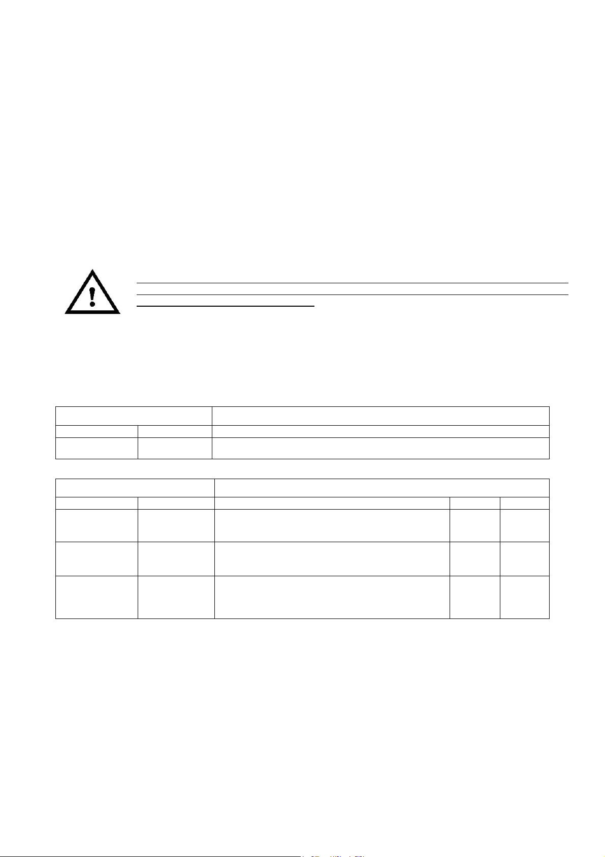
offthemotorpowerincaseoflowpressure(itisadry-workingexternalprotection).Theinverterhavetwoports
foranormally-closedgenericcontact:ENandConthelogicboard(fig.4).
Verifytheamountofpressurebetweenthewaterworksandthemaximumpumppressure,doesnotexceedthe
maximumpumppressurevalue(nominalpressure)
Besides,itisimportanttoputapressuregaugeontheoutletleader,soitispossibletoregulatethepressure
factorysettingvalue,accordingtotherealconditionsofthesystem.On the outlet leader it is necessary to install
a pressure gauge with an output signal between 0 – 5 Vdc or 4 – 20 mA; this signal is an input to the inverter.
Asaruleitwouldbebettertoinstallflexibleorrigidpipesoninletandoutletbranches,on-offvalvesoninletand
outletbranches,anoreturnvalve,amembranesurgetank.Toavoiddryingthesystemforreplacementofthe
membranesurgetank,pressuregaugeorpressuretransducer,itwouldbebettertoinstallsomeon-offvalves
betweenthetankconnectionandthesystem.Putthepressuretransducerdownstreamthenon-returnvalve,ifit
ispresent.Itwouldbebettertoinstallacock,usedduringthesystemcalibration;itisnotnecessaryifthereis
anexitnearthepump.Besurethesurgetankallowsthesystempressure.
Checkthepre-stresspressureofthesurgetankbeforeconnectingittothesystem.
5.3 Electric connections
Checkvoltageandfrequencyofthepowersupplyarethesameofthenominalvaluesofthecontrolsystem,that
arewrittenonthebox.Becertainofhavingagoodshort-circuitprotectioninyourelectricsystem.
Beforeworking,becertainallthecircuitiswithoutvoltage(alsotheconnectionsvoltageclear).Disconnectthe
inverterfromthepowersupplybeforeworkingonelectricalormechanicalpartsofthesystem.
Waitatleast2minutesafterthepowersupplydisconnectionbeforeworkingontheinverter;this
allow the capacitors discharge (in order to be sure they are completely discharged, the led
placedinsidetheinverter,ontheelectronicboard,havetobecompletelyswitchedoff).
Ifthelocalregulationaboutelectricsystemprovidesforamagneto-thermaldifferentialswitch,
installone.Selecttheprotectionwithcurveforalternativecurrentorpulsingcurrent(typeAorC).
Theunitisequippedwithallthosetechnicalarrangementsrequiredtoensureagoodfunctioningundernormal
situationsinstallation.
The control system has a entry-filter and it conforms to the EMC directive, also have a current overload
protectionwhichguaranteesabsoluteprotectionwhentheInverteriscombinedwithmotorsthatnotexceed the
maximumpower.
IMPORTANT: For EMCis necessary that thepower wires of control panel and motor power wires (when the
motorareseparatedfromtheinverter)areshieldedtype(orarmoured)withindividualconductorsofappropriate
section (current density <= 5 A/mm2). These cables must be the minimum length necessary. The screen
conductormustbeconnectedtothegroundbybothsides.Onmotorusethemetalcaseforconnectiontothe
groundofthescreen.
To avoid loops that can create mass disturbances radiated (antenna effect), the motor operated by the
frequency converter must be connected on the ground individually, always with a low-impedance using the
metallicboxofthemachine.
ThewiresfrompowersupplytofrequencyconverterandwiresfromfrequencyconverterÐmotor(ifthemotoris
separatedtotheInverter)mustbespacedasmuchaspossible,nottocreateloops,notmakethemrunparallel
lessthan50cm.
5.4 Motor-pumps phases connection
The single-phase inverter IMTP2.2 must be
installed on asynchronous three-phase motor
with 100-240Vac 50/60 Hz voltage supply.
Phases must be configured to Delta mode if
the motor is 230V / 400V (most common
case,asinFigure3).
Figure 3 – Delta motor phases connection

7 IMTP2.2-ITTP2.2/4/5.5/7.5 ENG
The three-phase inverters ITTP2.2 and
ITTP5.5/7.5mustbeinstalledonasynchronous
three-phase motor with 200-460 Vac 50/60 Hz
voltagesupply.Thephasesmustbeconnected
in star mode if the motor is 230V / 400 V
(mostcommoncase,asinFig4).
Figure 4 – Star motor phases connection
The unit is equipped with output over-current
protection; it is not necessary to install any
additionalsafetydevicebetweentheinverterandthepumpinordertoprotectthemotorincaseoffailure.
5.5 Electric connection to Line and Motor
SupplyforIMTP2.2deviceisasingle-phasevoltage100-240Vac,50/60Hz.
SupplyforITTP2.2andITTP5.5/7.5deviceisathree-phasevoltage200-460Vac,50/60Hz.
Theplanttowhichtheinverterisconnectedmustbeconformstosafetyregulationsinuse:
¥Differentialautomaticswitch:In=30mArecommendedtypeAorB(specificforInvertersload)
¥Magnetic-thermalautomaticswitchwithinterventioncurrentproportionatetothepowerof
thepumpinstalled(seeTable1)
¥Groundconnectionwithtotalresistancelessthan100½
Pumppower(kW) Magnetic-Thermalprotection(A)
0.37(0.5Hp) 4
0.75(1Hp) 6
1.5(2Hp) 12
2.2(3Hp) 16
3(4Hp) 20
4(5.5Hp) 25
5.5(7.5Hp) 32
7.5(10Hp) 40
Table 2: Magnetic-Thermal protection
Tomakeelectrical connectionsobservethefollowinginstructions(referencetoFigurefrom5to9):
· Opentheinverterboxunscrewingthe4screwsonthecover;
· WaitatleasttwominutesbeforeworkontheInvertertoensurethatthecapacitorsarefullydischarges;
· Fixthebottomoftheinverterboxtoterminalmotorcasewiththe4screws;
· Ifisnecessary,disconnectthetwocablesconnectorsfromthelogicboardJ1(26poles)eJ2(4poles)for
IMTP2.2-ITTP2.2(Figure5)orJ5(26poles)forITTP4/../7.5(Figure8);
· Connectthe3motor terminalsU,V,WonthepowerboardonIMTP2.2/ITTP2.2/../7.5(fig.6,7,9);use
theup-levelconnectorextensionforITTP4.0W,ITTP5.5W,ITTP7.5W;
· Connectthepressure transducerterminalsonthelogicboard(seeparagraph5.6);
· Optional 1 - enable contact: If possible connect the float switches or probe level (with NC contact)
betweenterminalsEN(enable,pole8ofJ9)andGND(common,pole8ofJ9)onthelogicboardofIMTP-
ITTP2.2(figure5)orbetweenEN(pole1ofJ11)andC(pole2ofJ11)onthelogicboardofITTP5.5/7.5
(figure8),replacingthewireconnectedbytheconstructor;
§ Optional2:MASTER – SLAVE Operating Mode on RS485 serial bus:inagroupofpumpscontrolledby
invertersconnectthetwowiresofRS485attheterminalJ10ofthelogicboardonIMTP-ITTP2.2oronJ2
ofthelogicboardofITTP4/../7.5,respectingthepolarityAorB;
§ Optional 3: Auxiliary ON/OFF Pump contact: for IMTP2.2 and ITTP2.2 version, there is a relay output
contact(3,4ofJ11,AUX-COM,fig.5)thatclosewhenthepressureislessthanthereferencevalueand
the motor velocity arrive to the maximum velocity, then re-open when the pressure is higher than the
referencevalue andtheflowarrivetotheminimumstopvalue; thisrelaycontactis2Ampere-250Vac
maximum,usefultodriveacontactorforasecondON-OFFpump,andworkonlywhenthecontrolgroup
mode is in Pressure mode; Warning: connect only contactors or relay coils with maximum voltage of
250Vac; For ITTP4.0/../7.5 this outputis12VDC-100mA on the poles markedwith AUX and"-"on J10
(fig.8) whichcan beconnectedto 12Vdccoil ofarelay,tocontrol asecondON / OFFpump, with the
samelogicinsertionandremovalmodelsdescribedaboveto2.2kW;

8 IMTP2.2-ITTP2.2/4/5.5/7.5 ENG
§ Optional 4 - only for IMTP-ITTP2.2: flow switch connection to detect the minimum flow stop in
mechanicalmode:connectthetwoterminalsoftheflowswitchon+15V(1ofJ8,fig.5)andPS2(3ofJ8,
fig.5)ontheLogicboard;thetwocontactcanbeinverted;
§ Optional5:forIMTP-ITTP2.2thereisrelayoutputcontact(1,4ofJ11fig.5,MOT.ON-COM)2AmpereÐ
250Vac max. that close when the motor is working; for ITTP4.0-5.5-7.5 between contacts MOTOR ON
andÒÐÒofJ10(fig.8)thereisa12Vdc200mAmax.signalwhentheMotorisworking;
§ Optional6: forIMTP-ITTP2.2there is relayoutputcontact (2, 4 ofJ11, ALARM-COM,fig.5) 2Ampere Ð
250Vacmax.thatclosewhenthereisanAlarmcondition;forITTP4.0-5.5-7.5betweencontactsALARM
andÒÐÒofJ10(fig.8)thereisa12Vdc200mAmax.signalwhenthereisanAlarm;
§ Optional7:forIMTP-ITTP2.2youcansupplya12Vdc-200mAmax.externalFan,connectingitbetween
5, 6 of J8 (FAN-GND, fig.5); for ITTP4-5.5-7.5 you can supply a 12Vdc - 200mA max. external Fan,
connectingitbetweencontactsVENTandÒÐÒofJ10(fig.8);
§ Connect the two line wiresand ground on L,N, GND for single-phase Inverter IMTP2.2(fig.6) or the
threelinewiresandgroundonL1,L2,L3,GNDforITTP2.2/../7.5(fig.7,9);usetheup-levelconnector
extensionforITTP4.0W,ITTP5.5W,ITTP7.5W;
§ Reconnect J1 and J2 connectors for IMTP-ITTP2.2 (fig.5) and J9 for ITTP4/../7.5 (fig.8) if previously
disconnected,makingsuretheyarefirmlyfixed;donÕtforgettheclamponJ9forITTP4/../7.5(fig.8);
· Replaceandclosetheboxusingthepreviouslyremovedscrews;
· Connectthepowersupplyplugtotheelectricline.
Beforeapossiblereopeningoftheinverterbox,afterfunctioning,switchoffthevoltagesupply
and wait at least 1 minute to be sure that the capacitors are completely discharged (danger:
contactwithelectrichighvoltageparts).
5.6 Pressure transducer connection, on different types
Table 3: pressure trasducer connections for IMP2.2-ITTP2.2
Table 4: pressure transducer connections for ITTP4/../7.5
StandardpressuretransducersK16andK25inuseare8Ð30VdcVoltagesupplyand4Ð20mAoutput.
TRASDUCER TYPE CONNECTIONS ON IMP-ITTP2.2 LOGIC BOARD
Supply Output Connections on J8
8Ð30Vdc 4Ð20mA 1 (+15V) Positivesupplyofthepressuretransducer(brownwireforK16orK25)
2 (PS1)Negativesupplyofthepressuretransducer(whitewireforK16orK25)
TRASDUCER TYPE CONNECTIONS ON ITTP4/../7.5 LOGIC BOARD
Supply Output Connections SW3-1 SW3-2
15Vdc 0Ð5Vdc
J6-1 (+15) Positivevoltagesupply
J6-3 (S) transducersignal
J6-6 (-)negativeVoltagesupply
OFF OFF
5Vdc 0Ð5Vdc
J6-2 (+5) Positivevoltagesupply
J6-3 (S)transducersignal
J6-6 (-)negativevoltagesupply
OFF OFF
8Ð30Vdc 4Ð20mA
J6-1 (+) Positivesupplyofthepressuretransducer
(brownwireforK16orK25)
J8-1 (S)Negativesupplyofthepressuretransducer
(whitewireforK16orK25)
ON ON

9 IMTP2.2-ITTP2.2/4/5.5/7.5 ENG
5.7 Connections on the electronic board
Figure 5: Logic board of IMTP2.2-ITTP 2.2

10 IMTP2.2-ITTP2.2/4/5.5/7.5 ENG
Figure 6: Power board of IMTP 2.2
Figure 7: Power board of ITTP 2.2

11 IMTP2.2-ITTP2.2/4/5.5/7.5 ENG
Figure 8: Logic board of ITTP 4/../7.5
Figure 9: Power board of ITTP 4/../7.5

12 IMTP2.2-ITTP2.2/4/5.5/7.5 ENG
6. STARTING AND PROGRAMMING
The starting and programming operations must be executed exclusively by experienced and
qualified staff. Use the appropriate equipment and protections. To supply voltage on the
InverterverifythattheInverterboxiscompletelyclosed,afterhavingcarefullyfollowedallthe
instructionswiringabove.
The pumpcan not run dry;functioning under theseconditions(even forashorttime) irreparably damage the
pumpitself.Forthisthecontrolsystemintervenesafteraboutaminute(usuallysufficienttimeforwaterloading
pumpduringtheinitialservice)withanalarm,stoppingthepumpasdescribedinChapter2.
Maketheairpurgingonthepump.Topreventtheentryofimpurityinthefirstputinservice,incaseofpumping
ofdrinkingwater,runanabundantrinsinganddisinfecting.
Themotor,canreachtemperaturesabove100¡C.Dangerofburnstosimplecontactwiththe
motor.
6.1 First Inverter Using – Self Regulation procedure
· PressSTARTandsetthenominal currentabsorbingforthephasesconnectioninuse(see5.3);
· PressSTARTandonrotation directionrequest,maintainingpulsedtheSTARTbuttonuntilthereadingof
electrical data measures and select the direction (0,1) with Ò+Ó and Ò-Ò buttons, finally confirming with
ENTER.
· Besurethatthepumpisfullyofwaterandclose completely the outlet of the pump.
· Pressing START for the Self-Regulation Check for the registration of the curve of the pump for the
regulationofthestopforclosedoutput.DuringtheCheckthedisplayshowÒEXECUTINGCHECKÓ;atthe
endofthechecktheInverterautomaticallysavedataandthepumpmayworknormally.
during Self-regulation Check the pump may arrive at the nominal velocity, with maximum
pressure.Ifyouneed,limitsthemaximumpressurepreviously(PumpData).
6.2 User’s check after Inverter setting
Check the pump stop for Minimum Flow: At the first installation open the output on the pump flow, press
START,waitafewsecondsfortheplantgotopressureset,thenclosetheoutputflow(slowly)andmakesure
thatthemotorstops(afterafewseconds)showingondisplay"MINIMUMFLOW".Incasethemotordoesnot
stopyoumustselectMOTORDATA-POWERSTOPandsetahighervaluethanthedefault(103%)setbythe
constructor.Theabsolutestoppowervalueisshowedatregulartimesondisplayatthetop-centralposition(see
fig.10).
Check pump dry-working: After installation, if itÕs possible, close the suction/intake of pump in order to
simulate a run dry situation; After a time of about 40 seconds (or the set delay time), the pump should stop,
displaying ÒDRY WORKING". If, after this time, the pump does not stop you must set into ADVANCED
FUNCTIONSÐPRESSURECONTROLsettingahighervalueoftheparameterCOSFILIMIT(bydefaultsetto
0.5).Savedataaftermodifying.

13 IMTP2.2-ITTP2.2/4/5.5/7.5 ENG
6.3 Programming Functions
·Display:
Figure 10: Display data
·List of command on the control panel
Command Description
FUN/MODE Toenteronmainfunctionsmenu
ENTER Toenteronthefunctionandmodifythevalues
+ Itallowsscrollinguptheitemsonthemenuorpositivechangeinthevalueofvariables;
afterthevariationpressENTER.
Encreasethereferencepressureduringfunctioning.
- Itallowsscrollingdowntheitemsonthemenuornegativechangeinthevalueof
variables;afterthevariationpressENTER.
Decreasethereferencepressureduringfunctioning.
ESC Toexittothefunctionandautomaticallysaving
START Pumpstart
STOP Pumpstop;IfpressedwiththekeyÒ-Òduring5secondsdoaRESET.
Table 5: List of commands on the control panel
·LED description
LED Description
PowerON · Greenfixed:inputvoltagesupplyON
MotorON · Greenfixed:Motorrunning;
· Greenflashing:beforestoppingforminimumflow
Alarm · Redfixed:Alarm(seeAlarmlistÐtable7).Requiremanuallyre-start
(STOP+START)
· Redflashinghighfrequency:Alarmandmotorstopwithautomaticre-start;
· Redflashinglowfrequency:ProblematthepressuresensorongroupfunctioningÐ
withoutstoppingpump
Table 6: Led description

14 IMTP2.2-ITTP2.2/4/5.5/7.5 ENG
·FUNCTIONS MENU DESCRIPTION
Main Menu Submenu Description
Lingua/Language
Italian
English
Spanish
Insertlanguagefordisplaycommand
showing.
Default:Italian
Dateadjurnment
Day
Month
Year
Hour
Minute
Second
Allowtodothedataregulation(dayÐ
monthÐyear)andthetime(hourÐminute
Ðsecond).ItIsimportanttosetinfollowing
conditions:
· SinglePumpwithprogramming;
· GroupofpumpsMaster-Slave.
ReferencePressure Referencepressure
[X.XBAR]
Pressurefollowedinfeedbackthrough
pressuresensor.
Thesameparametercanchangedirectly
duringpumpfunctioning,pushingÒ+ÓorÒ-Ò
onthecontrolpanel.
Default:3.0BAR
Motordata
(PASSWORDrequired)
Currentabsorbed[A]
Rotation[0/1]
Minimumflowpowerstop[%]
Dryworkingpowerstop[%]
Setthemotorcurrentreadingbymotor
ratingdata,accordingtothemotorphases
connectioninuse(star/triangle,see5.3).
Settherotationdirection(0/1)Ð
Default:0;
Regulationoftheminimumflowpowerfor
themotorstopinclosedoutputcondition;
Regulationofthedryworkingpowerstop
(default80%).
Pumpdata
(PASSWORDrequired)
MaximumPressure[BAR]
SelfregulationCheck[ON/OFF]
MaximumpressurelimitationÐ
Default:10BARonIMTP-ITTP2.2,16BAR
onITTP4/../7.5;
WithCheckonONmodeatthenext
STARTbegintheselfregulationcheck.
Sensordata
(PASSWORDrequired)
MIN[mA;V]
MAX[mA;V]
Range[BAR]
Flowsensor[0/NC/NO]
MIN:minimumoutputvaluepressure
transducerÐDefault:4.0mAÐ1.0V;
MAX:maximumoutputvaluepressure
transducerÐDefault:20mAÐ5.0V;
Range:measurerangeofpressure
transducerÐDefault:16BAR;
Flowsensor:0notenabled/1enabled;NC
normallyclosed;NOnormallyopen.
Advancedfunctions
(PASSWORDrequired)
Entertoadvancedfunctions
Toentertoadvancedfunctionsfor
advancedregulations(seetable7).
DataSaving
SavingdatamodifiedorReset
constructordata
Yes:savemodify
Not:backtopreviusdata
RESET:resetconstructordata
Table 7: Main Menu description

15 IMTP2.2-ITTP2.2/4/5.5/7.5 ENG
ADVANCED
FUNCTIONS MENU
Sub-menu
ADVANCED FUNCTIONS Description
Programming
Programs:
P1(start1)
A1(stop1)
É
P7(start7)
A7(stop7)
SelectStartProg.ONorOFF.
StartandStopsinthisformat:
Day:MonthÐHour:Minute
MotorLimits
1.NominalVoltage[V]
2.Nominalfrequency[Hz]
3.Maximumvelocity[%]
4.Minimumvelocity[%]
5.Acceleration[RPM/s]
6.Maximumcurrent[%]
1. NominalmotorVoltageÐDefault:230Vfor
IMTP2.2;400VforITTP2.2/../7.5;
2. NominalMotorfrequencyÐDefault:50Hz;
3. MaximumMotorVelocityÐDefault:102%;
4. MinimumMotorVelocity
5. Motoracceleration
6. MaximumMotorcurrentlimitÐDefault:105%
Values%onrespectthenominalvalues
PressureControl
1. PressureHysteresis[BAR]
2. Dryworkingre-startdelaytime
[min]
3. Minimumflowstopdelay[s]
4. Re-startdelayafterminimum
flowstop[s]
5. Drywiorkingstopdelay[s]
6. Coslimit
7. Alternatingtime[min]
1. Pressurecontrolhysteresis-Default:0.30
BAR;
2. Dryworkingre-startdelaytimeafterfirsts4th
try;afterthe5thtrytheInverterstopwith
manualre-start(STOP+START)ÐDefault:
15minutes;
3. DelaytimebeforeminimumflowstopÐ
Default:12second(15secondfor
ITTP4/../7.5);
4. Re-startdelaytimeafterminimumflowstop-
Default:1second;
5. DryworkingstopdelaytimeforpumpfillingÐ
Default:40seconds;
6. Whencosgodownthisvaluethepump
stopfordryworking(maybeabsenceof
inputwaterorair)ÐDefault:0.5;
7. Timeofthealternatingoftwoormorepumps
inMaster-slavegroupmode.
GroupFunctioning
Controltype
1. PumpPressure
2. PumpVelocity
3. MasterSlave
Referencevelocity[RPM]
Pumpsnumber(2..8)
Code(0..7)
SetControlType(Default:PumpPressure):
1.Pumppressure:feedbackcontrolofpressure
-needthepressuresensor;
2.Pumpvelocity:directlyregulationofthe
speedinabsenceofpressuresensor;
securitystopfornullflowanddryworking
conditions,onlywithmanuallyre-start.
3.MasterSlaveÐgroupfunctioningwithothers
InverterswithRS485serialbus.
PumpsNumber:Numberofpumpsingoup
functioning(2..8).
Code:0forMaster;>=1forSlave
P.I.D.factors
Kproportional
Kintegral
Pressureramp
·K proportional:0-100.PressureerrormultiplayerÐ
Default:25
·K integral:0-100.Integralofpressureerror
multiplier-Default:25
· Pressureramp[bar/s]:0.1-10.00ÐDefault:
0.5BAR/s
Alarmstory AlarmN¡
Type
Visualizationoflast100alarmevents(seetable
8)inchronologicorder.
Table 8: advanced functions sub-menu

16 IMTP2.2-ITTP2.2/4/5.5/7.5 ENG
6.4 Alarms
Alarm
Number Alarm Type Description
1 CurrentPeak Immediatelystopprobablycausedbyshort-circuit
Automaticre-start;finalstopafter10consecutiveevents
2 Over-Voltage Normallycausedbyovervoltagepicksupply.Automaticre-start;final
stopafter10consecutiveevents
3 InverterTemperature OvertemperatureIGBTprotection(90¡C)
Automaticre-start;finalstopafter10consecutiveevents
4 I2Texceeded Motorthermalprotectionrelatedtonominalcurrentset,formotor
insulationssavingathightemperatures.Automaticre-start;finalstopafter
10consecutiveevents
5 Dryworking Nullinputfloworairpresence;
Automaticre-start;finalstopafter5consecutiveevents
6 Pressuresensorproblem Pressuresensoroutputproblem
Automaticre-start;finalstopafter10consecutiveevents
7 Minimumflow Thepumpstopforminimumflowlimitachievement.It’s a normal
working condition of the system (nodemand
ofwateronthedelivery)eventhugisonthealarmlist,
Automaticre-start;nolimits
8 EnableOFF OpencontactbetweenENeC(figure5e8):stopthemotor;themotor
restartwhenthecontactwillcloseagain
9 Over-temperature
microprocessor
Themicroprocessortemperatureexceedalimitvalue,thenthesystem
muststopuntilthetemperaturereturnlow.
Automaticre-start;finalstopafter10consecutiveevents
10 Over-current Highcurrentcombinedwithalowlimitedvelocity.Automaticre-start;final
stopafter10consecutiveevents
11 Brakingcurrentpeak Currentpeakonthebrakingresistors;Automaticre-start;finalstopafter
10consecutiveevents
12 Errorcurrentreading Mistakeonthecurrentreading;themotorstoptopreventpossible
damagecausedbythefaultycurrentcontrol.
Automaticre-start;finalstopafter10consecutiveevents
13 InputVoltageunderlimit Inputvoltageundertheminimumworkinglimit.
Automaticre-start;finalstopafter10consecutiveevents
14 Unbalancedcurrent Unbalancedcurrentsonthethreephases(>15%onRMSvalue)
Automaticre-start;finalstopafter10consecutiveevents
15 INPUT-OUTPUTcablereverse Connectionmistake:VoltagesupplyconnectedontheoutputandMotor
cableconnectedontheentrance:reverseinordertoenablethemotor
Table 9: Alarms
6.5 Group Functioning - data transmission via serial bus RS485
Pumps controlled by inverters communicating with RS485 in control logic
MASTERÐSLAVEtype:
1. Connecting all Inverters with a bipolar signal cable for RS485,
respectingthepolarityAandB(J10clamponFig.5andJ2onfig.8);
2. Set the MASTER inverter: Advanced Functions Ð Group Functioning -
MasterSlave;Code=0;N¡Pumps(³2);
3. Set on the remaining SLAVES Inverters (maximum 8): Advanced
FunctionsÐGroupFunctioning-MasterSlave;Code(³1);N¡Pumps(³2).
IMPORTANT: The Master-Slave group setting may be done after the self-
regulation check, as described on 6.1. Use one sensor for every Inverter to
guarantee the redundancy and the group functioning continuity in case of
damage of one of the Motors/Sensors/Inverters; when a sensor have a
problem the Master Inverter read the output of a sensor connected to one
otherslaveInverter.ForthisfunctioningisimportantthegoodstateofchargeofthebatteryofMasterInverter,
tomaintainthedate.
DuringgroupfunctioningincaseofbreakvoltageorfaulttotheMasterInverterortotheserial
bus cable, the others Inverters continuous functioning in single mode, reading their pressure
sensors. Although there is not inefficiency of the complete system, restore the damaged
cable/sensor/inverter in order to guarantee the perfect pressure control and the perfect
alternationofthepumpsanditsduration.

17 IMTP2.2-ITTP2.2/4/5.5/7.5 ENG
6.6 Replacing the battery
ThelithiumbatteryCR2032forIMTP-ITTP2.2andCR2430forITTP4/../7.5areusedexclusivelyforstoringdate
and time evenin the absence of powersupply fora long time (thebatterycan live4-6 years withoutinverter
powersupply).Thelithiumbatteryshouldbereplacedwhentheusernoticethattheinverterdoesnotmaintain
storeddateandhourintheabsenceofpowersupply.
NOTE:Evenwithexhaustedorabsentlithiumbatteryremainstoredallinverterfunctionalsettingsindefinitely.
Toreplacingthelithiumbatteryitneeds:
1.Disconnectthepowercablefromtheline;
2.OpentheinverterboxunscrewingtheNo.4screws;
3.Waitforthecompleteshutdownoftheledwhichindicatesthechargeofcapacitorsbefore
touchinganypartofelectronicboards;
4.Replacethebatterypresentunderthecoveroftheinverter.
7. SOLUTION OF THE MOST COMMON PROBLEMS
N° Possible Problem Possible solution
1
Pressingstartbuttonthemotor
donÕtstartorstartandstopafter
fewsecondsandtheinverter
showOver-Currentalarmor
CurrentPickalarm
Checkiftheinput/outputoftheinverterarerespectlyconnectedbetweenlineand
motor,withoutinversion(Warning:input/outputinversioncandamagetheelectronic
boardoftheinverter).
Checkthecorrectconnectionofthepump(star/delta):possiblemistake.
Checkifallthethreewirestothemotorareconnectedgoodandthethreecurrentare
balanced.
Checkifthemotorpowersizeisnotsohighonrespecttotheinvertersize.
CheckiftheinverterisnotonMaster-Slavecondition(AdvancedFunctions->Group
Functioning)settoslave,withouttheMasterinverterconnectedandswitchedon:in
thissituationwaiting30safterpressingstartbutton,theinverterwillstartautomatically
alone.
2
Pressingstartbuttonthemotor
donÕtstartorstartandstop
immediatelyandtheinverter
showUnderVoltagealarm
Checkthatalltheinputvoltagesupplywiresareconnectedgoodontheentranceof
theinverter:iftheinverterinputisthree-phasesbutontheconnectionthereareonly
two,theinverterswitchonandcanstartthemotor,buthavenÕtenoughpowerto
supplyit.
Checkthatbeforetheinverterthesupplylinewiressizearegoodtohavealimited
voltagedrop,thenasufficientvoltagevalueontheinverter.
3
Duringworkingatthemaximum
powertheinverterreduce
continuouslytheoutputpowerto
themotorthenstopthemotor
andtheinvertershowOver
TemperatureIGBTalarm
/InverterTemperaturealarm
Temperatureoftheelectronicboardoftheinverteristoohighandtheinvertermust
remainstopforfewminutestoreducetheinternaltemperaturebeforetheautomatic
restart.
Forwallmountingtypebesurethattheinverterstandonawall,inverticalposition,
protectedfromdirectlysunlight,andtheairflowistotallyfree;formotormountingtype
checkthattheairflowfromthemotorfanisgoodtolimitthealuminumtemperatureof
theinvertercaseunder60¡C;theinvertercannotworkcontinuouslyatthemaximum
powerwithaambienttemperaturehigherthan40¡Candwithhightemperaturecan
reduceautomaticallytheoutputpower(-10%,-20%thenstopforfewminutes)..
4
PressureTransducerdonÕt
measurethecorrectpressure
value(error>1Bar)
Checkifthepressuretransducerisconnectedonthedeliveryofthepumpona
correctposition,notsoclosetotheimpellersandbeforethevalvetoclosetheflow.
5
PressureTransducermeasurea
pressuretoohighwhenthe
motorisrunningthenthe
Inverterreducethemotor
velocityattheminimumvalue
(lowfrequency)
Checkthatthepressurecableisseparatedfromthemotorcable,thatisasourceof
noise;speciallywhenthecableofthepressuretransduceristoolong(longdistance
betweeninverterandmotor)itÕsveryimportanttouseashieldedtypetwowirecable,
asfaraspossibletothemotorsupplycable.Connecttheshieldtogroundonlyonone
terminal,ifpossibleconnectitdirectlyonametalscrewtogroundnearthemotor.
6
TheInvertercannotwork
becauseremaininPressure
TransducerProblemalarm
condition
CheckIfthewiresofthepressuretransducerarecorrectlyconnectedbrownon+,
whiteonScontactontheboard.
Checkwiringconnectiononthecableofthepressuretransducer.
Warning:Incaseyouneedtocutthepressuretransducercabletoaddalongercable
besuretoswitchofftheinverteratleast1minutebeforetocutthiscable,otherwise
youcancauseashortcircuitonthetransducerinputoftheelectronicboard(damage)
iftheinternalcapacitorsarenottotallydischarged.
7
ThedistancebetweenPressure
transducerandPumpishigh
(longpipe)andthepressure
continuouslygoupanddown
YoumustreducethevelocityofthefeedbackcontrolreducingtheProportionalfactor
andtheIntegralfactor(AdvancedFunctions->P.I.D.Factors).Trytosetthesevalues
tohalfandtestthesystem,then,ifnotenough,reducemoreandtestagainuntilthe
pressurecontrolremainstable.

18 IMTP2.2-ITTP2.2/4/5.5/7.5 ENG
8
TheInverterstopthemotorfor
MinimumFlowwithahighflow
conditionandthenre-startand
stopagain,continuously
AsmallwatermembraneTankchargedwith1.5-2Barairpressureisrequiredfora
correctworking;checkit.
Theconditionmayalsocausedbyanotcorrectpumpcurvesavingduringthe
automaticcheck:possiblythedeliverywasnottotallyclosedandtheInverterchecked
ahighercurveofthepump;repeattheautomaticcheck(Pumpdata->checkON,
thenexittothemenuandpressSTART)closingtotallytheoutletandtryagainthe
functioning.
Verifyifthereisano-returninletvalveonthepumpandifitÕsworkinggoodwithout
loses.
ItÕspossibletoreducetheflowbeforestoppingreducingtheparameterF1
ItÕspossibletoreducetheflowbeforestoppingreducingtheparameterMinimumFlow
Powerstop%onMotorData.
9
TheinverterdonÕtswitchoffthe
pumpwhenthevalveon
deliveryistotallyclosed
Probablycheckwasdonewithpumpnotperfectlyfilledup;remakethecheck
procedureafteracompletefillingofthepumpandtryagainifpumpswitchoffcorrectly
inminimumflowcondition.Iftheproblemremain,trytogrowupthefunction:
AdvancedFunctions->Motordata->Minimumflowpowerstop,upgrading2%every
timeandtestingpump,tillfindthecorrectworking.
10
Thehydraulicsystemhaveabig
tank(>40l)and,aftercheckdid
correctlywithcloseddelivery,
thepumpstopforminimumflow
withahighflow,andthenre-
startandstopagain,
continuously
Probablyduringtheautomaticchecktherewasaflowofwatertofullupthebigtank,
forthatthepumpcurvesavedbytheinverterisnotthecorrectcurve(withnullflow
andmaximumpressure).
Maintainfullofwaterthetank(pressurenearmaximumvalue);repeattheautomatic
check(Pumpdata->checkON,thenexittothemenuandpressSTART).Whenthe
checkfinishtrytoworkagaintestingtheminimumflowstopconditionofthemotorthat
mustbewithasmallflow.
11
TheInverterstopthemotorfor
DryWorkingcondition
SometimestheproblemiscausedbythesameAutomaticCheckerrorthatprevious
point(seepossiblesolutionlikeabove).
Inothercasespossiblythereisairmixedwiththewaterontheinletofthepump
(verifypipesandjunctions).
12
ThepumpdonÕtswitchofffordry
workingwhentheinletpipeand
thepumpareempty
Innormalworkingcondition,withpumpandpipesfilledup,remakeacheckprocedure
(Pumpdata->Check=ON)andtryagain.Iftheproblemremaingrowupthe
parameter:MotorData->DryWorkingpowerstop,from80%defaultvaluedoing10%
steps,testingeverytimethepump.IftheproblemcannotdisappearalsowithDry
workingpowerstopmorethan100%,verifythatpumphavenÕtanydefect(faultseal,
impellers,etc)thatcancauseabigpowerabsorbingalsowithoutwater,indry
condition.
13
Agroupoftwoormoreinverters
cannotcommunicatebetween
eachotherinMaster-Slave
mode
FortheBCinverterstypereadonleft.
FortheRStypecheckthecorrectconnectionRS485byatwowirescable(AtoAand
BtoB).
VerifythecommunicationsettoMaster-SlaveonAdvancedFunctions->Group
Functioning(code0fortheinverterMaster,code1,2,etcforalltheothersInverters
Slave)
14
TheInverterconductonthe
inputvoltagesupplyline
electromagneticnoisesthat
disturbotherelectronicdevices
CheckGroundcableconnections(Groundsystemmustberadialtype,withresistance
lessthan10Ohm).
AlltheInvertershaveaninternalInputEMCfilteringstadium,butisavailablealsoan
additionalEMCInputfilter(varioustypes,contacttheservice)forbiggernoise
suppressionwithsensitivedevicesconnectedontheline.
15
Withalongcablebetween
InverterandMotorsometimes
theinverterstopthemotorin
PickCurrentalarm
ThemotorcanhavehighpickvoltagevaluecausedbythehighfrequencyofthePWM
combinedwiththehighcapacitancetogroundofthelongcable:wesuggesttousean
additionalinverteroutputfilterforcablelongerthan40metersconnectingitdirectlyon
theInverteroutput.Availablevarioustypesofoutputfilters,contacttheserviceto
receiveinformations.
16
TheDifferentialCircuitBreaker
onthelinesometimesswitchoff
theinverter
ChecktheGroundsystemresistance(mustbelessthan10Ohm).
UseonlydifferentialcircuitbreakertypeA(specificforInverters).
17
TheMagneto-ThermalCircuit
Breakeronthelineswitchoffthe
inverterwhenthepumprunat
themaximumpower
Alltheinvertersmayhaveahighpickvalueofthesinusoidalcausedbytheharmonics
(5th,7th,11th,etc.)anddependingbytheresistanceoftheline,butthiscondition
donÕtincreasetheenergyabsorbingvaluedependingbytheareaunderthiscurrent
curve.OnlyyouneedtouseaMagneto-ThermalCircuitBreakerwithahigherCurrent
valuethanthevaluethatyoucanuseforthedirectpumpcontrolled.UsuallyitÕs
enoughaswitchonestephigherthantheswitchusefulforthesimplemotor(see
tableoftheMagneto-Thermalprotectionsuggestedonthehandbook).
Table 10: solution of the most common installing problems
8. GUARANTEE
UnderthecurrentEuropeanlow:guaranteeof2yearscalculatedfromthedateofdeliveryofprejudicefurther
provisionsoflaworcontract.
Tohaveserviceinguarantee,itmustsubmittothecompanyprovidingtheguaranteecertificatecompleted.
The guarantee is excluded or interrupted in anticipation if the damage is caused to the following:
External influences, non-professional installation, non-compliance with instructions, interventions by
unauthorizedlocations,useofnotoriginalsparepartsandnormalwear.

19 IMTP2.2-ITTP2.2/4/5.5/7.5 ENG
9. DICHIARAZIONE DI CONFORMITA’ / DECLARATION OF CONFORMITY
dichiaracheiprodottiInverterelencati/declare that the products:
IMTP2.2M-RS;
ITTP2.2M-RS;
ITTP4.0M/W-RS;
ITTP5.5M/W-RS;
ITTP7.5W-RS;
Sono conformi alle disposizioni delle seguenti direttive europee e alle disposizioni nazionali di attuazione in
base alle seguenti norme tecniche / Are conform to the following European directives and to national law
following the technical standards:
· Machines98/37/CE
· LowVoltage73/23/CEesuccessivemodifiche/and subsequent amendments
· IECEN61000-6-1
· CEIEN61000-6-4
· ETSIEN301489-1V1.9.2
· ETSIEN301489-3V1.4.1
· CEIEN55014-2;
· CEIEN50178.
· CEIEN55022:2009-01
· CEIEN60335-1;
· CEIEN60335-2-41;
· CEIEN61000-3-2;
· CEIEN61000-3-3;
· CEIEN61000-3-4;
· CEIEN61000-3-12;
· CEIEN61000-4-2:2011-04
· CEIEN61000-4-3:2007-04
· CEIEN61000-4-3/A1:2009-01
· CEIEN61000-4-3/A2:2011-01
· CEIEN61000-4-4:2006-01
· CEIEN61000-4-4/EC:2008-02
· CEIEN61000-4-5:2007-10
· CENELEC61000-4-6:2005-07
· CEIEN61000-4-6:2010-07

Reliability is our trademark
3885-530 Esmoriz
Rua do Campo Grande, nº 15
Zona Ind. Esmoriz - Sector C
8º36'13.86"O
GPS:
OLIJU Manufacturing
40º57'27.11"N
PORTUGAL
PORTUGAL
4520-475 Rio Meão
Zona Industrial de Rio Meão
Avenida Santiago, N.º 43
40º57'37.20"N
8º35'50.10"O
GPS:
OLIJU Comercial
oliju@oliju.com
http://www.oliju.com
+351.256.780910
+351.256.783880
This manual suits for next models
9
Table of contents
Popular Inverter manuals by other brands

Schumacher Electric
Schumacher Electric PI-750 owner's manual

SolaX Power
SolaX Power X3-MEGA G2 Series user manual

AQUASTREAM
AQUASTREAM ABSC02787 Installation, operation & maintenance manual

Mastervolt
Mastervolt WHISPER 6 ULTRA installation manual

Yamaha
Yamaha EF1000iS owner's manual

Kipor
Kipor KG390 Service manual