Cloos GLW 222 AC/DC Guide

Operating
instructions and
Spare parts
GLW 222 AC/DC
Portable Inverter
Rev.1
- EN -

2
Carl Cloos Schweisstechnik GmbH
Industriestrasse
35708 Haiger
Germany
Telephone: (0 27 73) 85-0
Telefax: (0 27 73) 85-275
E-Mail: [email protected]
Internet: http://www.cloos.de
RW - FP - Rev.0
release date: 10.12.15
Keep for further use.

3
CARL CLOOS Schweißtechnik GmbH
Industriestraße
35708 Haiger
Tel.(+49) 2773/85-0
Fax.(+49) 2773/85-275
mail: [email protected]
www.cloos.de
Dokument: QIGLW222 Monat/Jahr: 10/12
EG-Konformitätserklärung
im Sinne der EG-Richtlinien 2006/95/EG (Niederspannung) und 2004/108/EG (EMV)
Bezeichnung des Gerätes: WIG Schweissgerät
Typbezeichnung: QINEO GLW 222 AC/DC
Fabriknummer: siehe Typenschild (Geräterückseite)
Folgende EG-Richtlinien sind angewandt:
- EG-Niederspannungsrichtlinie (2006/95/EG)
- EG-Richtlinie Elektromagnetische Verträglichkeit (2004/108/EG)
- EG-Richtlinie RoHS (2002/95/EG)
Folgende harmonisierte Normen sind angewandt:
- EN 60974-1 Lichtbogenschweißeinrichtungen
Teil 1: Schweißstromquellen
- EN 60974-3 Lichtbogenschweißeinrichtungen
Teil 3: Lichtbogenzünd- und stabilisierungseinrichtungen
- EN 60974-10 Lichtbogenschweißeinrichtungen
Teil 10: Anforderungen an die elektromagnetische Verträglichkeit (EMV)
Hersteller Unterschrift: Dipl.-Kfm. Ralf Pulverich
Angaben zum Unterzeichner: Geschäftsführer
Hiermit erklären wir, dass das nachfolgend aufgeführte Gerät in Übereinstimmung mit
den EU-Richtlinien entwickelt, konstruiert und gefertigt sowie in den Verkehr gebracht wurde.
Wesentliche Umbauten oder Erweiterungen, die nicht durch den o. g. Hersteller oder durch seine
befugten Vertreter durchgeführt wurden, führen zum Erlöschen dieser Konformitätserklärung.

GLW 222 AC/DC
Cod.006.0001.1481
14/05/2014 v2.4
ENGLISH
0
3/34
1INTRODUCTION .....................................................................4
2FRONT PANEL .......................................................................4
3REAR PANEL .........................................................................5
4INSTALLATION ......................................................................5
4.1 CONNECTIONS TO THE ELECTRICAL MAINS NETWORK.5
4.2 PREPARING FOR MMA WELDING........................................5
4.3 PREPARING FOR TIG WELDING ..........................................6
5USER INTERFACE .................................................................8
6UNIT POWER-UP....................................................................9
7RESET (LOAD FACTORY SETTINGS)..................................9
7.1 PARTIAL RESET.....................................................................9
7.2 TOTAL RESET ......................................................................10
8SET-UP (INITIAL SET-UP OF THE WELDING POWER
SOURCE) ..............................................................................10
8.1 TORCH LOADING.................................................................12
9ALARMS MANAGEMENT ....................................................12
THERMAL ALARM! ..........................................................................12
COOLING DEVICE ALARM..............................................................12
10 WELDING PARAMETERS....................................................13
Welding current.................................................................................13
Max welding current..........................................................................13
Hot-start ............................................................................................13
Arc-force............................................................................................13
VRD...................................................................................................13
Long arc voltage ...............................................................................13
Remote control..................................................................................13
Dynamic arc ......................................................................................13
Second current Bi-level.....................................................................13
Base current......................................................................................13
Peak time..........................................................................................14
Base time..........................................................................................14
Pulse frequency ................................................................................14
Slope down .......................................................................................14
Final current......................................................................................14
Post-gas............................................................................................14
Pre-gas..............................................................................................14
Start current ......................................................................................14
Slope up............................................................................................14
Spot TIG time....................................................................................14
HF arc start .......................................................................................14
Minimum pedal current .....................................................................14
Q-start ...............................................................................................14
Multi-tack...........................................................................................14
AC wave in mix AC-DC.....................................................................14
Extra fusion.......................................................................................14
AC frequency ....................................................................................15
AC balance .......................................................................................15
Electrode diameter............................................................................15
10.1 PARAMETERS ACTIVATION ...............................................16
11 WELDING SETTINGS...........................................................18
11.1 ELECTRODE WELDING (MMA) ...........................................18
11.1.1 MMA PARAMETERS SETTING (1ST LEVEL).................................18
11.1.2 MMA PARAMETERS SETTING (2ND LEVEL) ................................18
11.1.3 MMA SPECIAL FUNCTIONS ...........................................................18
11.2 DC TIG WELDING.................................................................19
11.2.1 DC TIG PARAMETERS SETTING (1ST LEVEL).............................19
11.2.2 DC TIG PARAMETERS SETTING (2ND LEVEL) ............................19
11.2.3 DC TIG SPECIAL FUNCTIONS MENU............................................20
11.3 AC TIG WELDING.................................................................21
11.3.1 AC TIG PARAMETERS SETTING (1ST LEVEL) .............................21
11.3.2 AC TIG PARAMETERS SETTING (2ND LEVEL).............................21
11.3.3 AC TIG SPECIAL FUNCTIONS MENU............................................22
12 JOBS MANAGEMENT..........................................................23
12.1 SAVING A JOB......................................................................23
12.2 LOADING A USER JOB OF FACTORY SET JOB................23
12.3 DELETING A JOB .................................................................23
13 TORCH TRIGGER MODES ..................................................24
13.1 2T LIFT-ARC WELDING........................................................24
13.2 2T HF WELDING...................................................................24
13.3 4T LIFT-ARC WELDING .......................................................24
13.4 4T HF WELDING...................................................................25
13.5 BI-LEVEL LIFT WELDING ....................................................25
13.6 BI-LEVEL HF WELDING.......................................................25
13.7 2T SPOT WELDING..............................................................25
13.8 2T SPOT HF WELDING........................................................26
13.9 PILOT ARC WELDING..........................................................26
14 TECHNICAL DATA...............................................................27
15 SPARE PARTS..................................................................... 28
16 ELECTRICAL DIAGRAM ..................................................... 30
16.1 GLW 222 AC/DC...................................................................30
16.2 TORCH CONNECTOR .........................................................31
16.3 REMOTE CONTROLLER CONNECTOR .............................31

Cod.006.0001.1481
14/05/2014 v2.4
ENGLISH
GLW 222 AC/DC
4/34
1INTRODUCTION
IMPORTANT!
This handbook must be consigned to the user prior to
installation and commissioning of the unit.
Read the "General prescriptions for use" handbook supplied
separately from this handbook before installing and
commissioning the unit.
The meaning of the symbols in this manual and the associated
precautionary information are given in the "General
prescriptions for use”.
If the "General prescriptions for use" are not present, it is
mandatory to request a replacement copy from the manufacturer
or from your dealer.
Retain these documents for future consultation.
KEY
This symbol identifies an action that occurs automatically as a
result of a previous action.
This symbol identifies additional information or a reference to
a different section of the manual containing the associated
information.
§
This symbol identifies a reference to a chapter of the manual.
This symbol accompanies important information concerning
the execution of the relevant operations.
GLW 222 AC/DC is an advanced technology single-phase welding
power source for AC and DC TIG welding operations.
AC TIG functions are ideal for aluminum, magnesium and related
alloys welding.
Mild steel, stainless steel and copper can be easily welded in DC TIG.
AC TIG welding is optimized thanks to:
Synergic arc ignition selection located on the front panel, it
modifies the ignition according to electrode diameter.
Extra fusion function maximizes arc focusing for considerable thin
material in AC TIG welding.
Mixed AC/DC increases arc penetration for thick aluminum plates.
Pulsed AC TIG mode which prevents the risk of deformation of the
workpiece in the case of prolonged welding operations.
Up to 4,00mm diameter electrode welding is possible in MMA.
The fan is turned on only during welding, at the end of the welding
process it remains on for a fixed period of time according to welding
conditions.
The fan is nonetheless controlled by specific thermal sensors that
guarantee a correct cooling of the machine.
The welding modes and procedures available are those indicated in
the table.
MODE
PROCEDURE
MMA
TIG DC
CONTINUOUS
2 STEP LIFT-ARC (2T)
2 STEP SPOT (2T-SPOT)
+
PULSED DC TIG
+
2 STEP + HF (2T HF)
2 STEP HF SPOT (2T-SPOT
HF)
+
TIG DC SYNERGIC
4 STEP LIFT-ARC (4T)
+
4 STEP + HF (4T HF)
TIG AC
CONTINUOUS
4 STEP BI-LEVEL (4T B-
LEVEL)
+
PULSED AC TIG
+
4 STEP BI-LEVEL + HF (4T B-
LEVEL HF)
Accessories that can be connected to the unit:
manual remote controller for remote adjustment of the welding
current.
foot-pedal remote controller for TIG torch arc striking and remote
adjustment of welding current.
UP/DOWN torch or torch with potentiometer.
liquid cooler for TIG torches.
2FRONT PANEL
1 4 3 2
1: Negative pole welding socket.
2: Positive pole welding socket.
3: Connector for logic signals of TIG torch.
4: Connector for gas feed hose:
power source torch

GLW 222 AC/DC
Cod.006.0001.1481
14/05/2014 v2.4
ENGLISH
0
5/34
3REAR PANEL
2 3 1
4 5
1: Welding power source ON/OFF switch.
2: Remote controller connector.
3: Connector for gas feed hose:
cylinder power source
4: Power cable.
Total length
(including internal part)
2,5 m
Number and cross section of wires
3 x 2,5 mm2
Type of plug supplied
Schuko
5: Cooler power feeding connector.
Voltage
230 V~
Current output
1.35 A
IP protection rating
IP20 (cap open)
IP66 (cap closed)
WARNING!
High voltage!
If the socket is not connected to any devices always close the cap:
presence of hazardous voltage levels!
4INSTALLATION
WARNING!
Lifting and positioning
Read the warnings highlighted by the following symbols in the
“General prescriptions for use”.
4.1 CONNECTIONS TO THE ELECTRICAL MAINS
NETWORK
The characteristics of the mains power supply to which the equipment
shall be connected are given in the section entitled “technical data” on
page 27.
The machine can be connected to motorgenerators provided their
voltage is stabilised.
Connect/disconnect the various devices with the machine switched
off.
4.2 PREPARING FOR MMA WELDING
1. Set the welding power source ON/OFF switch to “O” (unit de-
energized).
2. Plug the power cable plug into a mains socket outlet.
3. Choose the electrode based on the type of material and thickness
of the workpiece to be welded.
4. Insert the electrode in the electrode holder.
5. Connect the electrode holder clamp plug to the following welding
socket: Positive pole welding socket.
6. Connect the earth clamp plug to the following welding socket:
Negative pole welding socket.
7. Connect the earth clamp to the workpiece being processed.
WARNING!
Electric shock hazard!
Read the warnings highlighted by the following symbols in the
“General prescriptions for use”.
8. Set the welding power source ON/OFF switch to “I” (unit
powered).
9. Select the following welding mode on the user interface: MMA
10. Set the required welding parameter values on the user interface.
When the remote controller [RC] is connected and the relative
locking screw is tightened, welding current can be adjusted using
the remote controller.
The system is ready to start welding.

Cod.006.0001.1481
14/05/2014 v2.4
ENGLISH
GLW 222 AC/DC
6/34
4.3 PREPARING FOR TIG WELDING
Installation with cooling unit
1. Set the welding power source ON/OFF switch to “O” (unit de-
energized).
2. Remove the screws from the power source cabinet.
3. Loosen the screws of the upper brackets of the cooler and open
out the brackets slightly.
4. Place the power source on top of the cooler.
5. Secure the cooler brackets to the power source using the
previously removed screws.
6. Connect the plug of the cooler power cable to the cooler power
socket on the rear panel of the welding power source.
7. Set the cooler ON/OFF switch to “I” (unit powered).
8. Plug the power cable plug into a mains socket outlet.
9. Connect the gas hose from the welding gas cylinder to the rear
gas socket.
10. Open the cylinder gas valve.
11. Connect the gas hose from the welding torch to the front gas
socket.
12. Connect the torch plug to the welding socket on the basis of the
polarity required by the type of electrode in question.
13. Choose the electrode based on the type of material and thickness
of the workpiece to be welded.
14. Insert the electrode in the TIG torch.
15. Connect the plug of the ground clamp to the welding socket on the
basis of the polarity required.
16. Connect the earth clamp to the workpiece being processed.
17. Set the welding power source ON/OFF switch to “I” (unit
powered).
18. Select the following welding mode on the user interface: TIG DC /
TIG AC
19. Press the torch trigger with the torch well clear of any metal parts.
This serves to open the gas solenoid valve without striking the

GLW 222 AC/DC
Cod.006.0001.1481
14/05/2014 v2.4
ENGLISH
0
7/34
welding arc.
20. Use the flow control valve to adjust the flow of gas as required
while the gas is flowing out.
21. Set the required welding parameter values on the user interface.
When the remote control pedal is connected and the relative
locking screw is tightened the welding current will vary in relation
to the pressure exerted on the pedal.
The system is ready to start welding.
Cod.006.0001.1481
14/05/2014 v2.4
ENGLISH
GLW 222 AC/DC
8/34
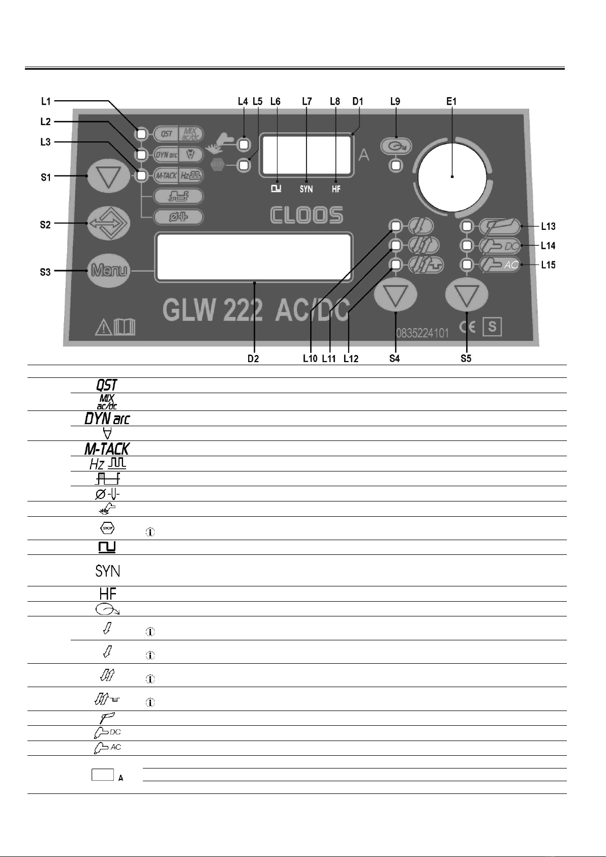
5USER INTERFACE
CODE
SYMBOL
DESCRIPTION
L1
DC TIG mode: Illumination shows that the following function has been activated: Q-START
AC TIG mode: Illumination shows that the following function has been activated: AC WAVE IN MIX AC-DC
L2
DC TIG mode: Illumination shows that the following function has been activated: DYNAIC ARC
AC TIG mode: Illumination shows that the following function has been activated: FUSIONE EXTRA
L3
DC TIG mode: Illumination shows that the following function has been activated: MULTI TACK
AC TIG mode: When this LED illuminates the following parameter can be set: AC FREQUENCY
AC TIG mode: When this LED illuminates the following parameter can be set: AC TIG BALANCE
AC TIG mode: When this LED illuminates the following parameter can be set: ELECTRODE DIAMETER
L4
This LED illuminates to confirm the presence of power on the output sockets.
L5
This LED illuminates to show an anomaly in the operating conditions.
See “ALARMS MANAGEMENT”(§ 9 page 12).
L6
This LED illuminates to show that the following welding mode is selected: TIG PULSED
L7
DC TIG mode: When this LED illuminates the following parameter can be set: TIG SYNERGIC PULSE
When this is on, it means that the synergic mode is active and that the operator can set just the welding current while the other parameters are
automatically regulated by the machine. The synergy is optimised by angle welding.
L8
Illumination shows that the following function has been activated: High frequency arc strike (HF)
L9
This LED indicates that the current reference setting is imposed by the remote controller.
L10
Illumination shows that the following function has been activated: 2 times procedure
§ 13.1 page 24 / § 13.2 page 24
A flashing signal means the following function is activated: 2 times procedure
§ 13.7 page 26 / § 13.8 page 26
L11
Illumination shows that the following function has been activated: 4 times procedure
§ 13.3 page 24 / § 13.4 page 25
L12
Illumination shows that the following function has been activated: 4 times Bi-level procedure
§ 13.5 page 25 / § 13.6 page 25
L13
This LED illuminates to show that the following welding mode is selected: MMA
L14
This LED illuminates to show that the following welding mode is selected: TIG CONTINUOUS
L15
This LED illuminates to show that the following welding mode is selected: AC TIG
D1
Parameters/functions setting: The displays show the value of the following parameter: WELDING CURRENT
Welding: The display shows the effective amperes value during welding.
HOLD function: The display shows the latest measured current value.

GLW 222 AC/DC
Cod.006.0001.1481
14/05/2014 v2.4
ENGLISH
0
9/34
D2
Data setting: The display shows the various welding menus relative to the selected processes.
The display shows the selected parameter.
S1
AC TIG mode: Press the button to select the parameter to be set. Possible choices:
Extra Fusion
AC Frequency
AC Balance
S2
Press the button once to open the JOB upload menu.
Hold down the button for 3 seconds to gain access to the JOB save/delete menu.
S3
Press the button once to select the parameters of the first level menu.
Hold down the button for 3 seconds to gain access to the second level menu.
Hold down the button at the time of power-on to gain access to the SETUP menu.
S4
This button selects the torch trigger procedure.
§ 13 page 24
S5
This button selects the welding mode.
E1
Parameters/functions setting: The encoder provides the facility to alter the selected parameter.
Welding: The encoder allows the welding current to be modified.
6UNIT POWER-UP
Set the welding power source ON/OFF switch to “I” to switch on the unit.
221AC/DC
Fx.x
The message appears on the following displays: D2
x.x=
software version
First power-up or power-ups following a RESET procedure
The welding power source sets up for welding with the factory presets.
Subsequent power-ups
The welding power source sets up for welding in the latest stable welding configuration that was active at the time of power-off.
7RESET (LOAD FACTORY SETTINGS)
The reset procedure involves complete restoration of the default values, parameters and memory settings set in the factory.
The reset procedure is useful in the following cases:
Too many changes made to the welding parameters so user finds it difficult to restore defaults.
Unidentified software problems that prevent the welding power source from functioning correctly.
7.1 PARTIAL RESET
The reset procedure involves restoration of the parameter values and settings, except the following settings:
settings of the SETUP menu
saved JOBS
set language
Set the welding power source ON/OFF switch to “O” to switch the unit off.
S3
S5
Hold down both buttons simultaneously.
Set the welding power source ON/OFF switch to “I” to switch on the unit.
SIMULTANEOUS ACTIONS
RECALL PARTIAL SETUP ?
The message appears on the following displays: D2
Exit without confirmation
Press any button (except S2).
This action will automatically close the menu.
Exit with confirmation
S3
Press the button.
This action will automatically close the menu.
Wait for the memory clear procedure to terminate.

Cod.006.0001.1481
14/05/2014 v2.4
ENGLISH
GLW 222 AC/DC
10/34
7.2 TOTAL RESET
The reset procedure involves complete restoration of the default values, parameters and memory settings set in the factory.
All memory locations will be reset and hence all your personal welding settings will be lost!
Set the welding power source ON/OFF switch to “O” to switch the unit off.
S3
S5
Hold down both buttons simultaneously.
Set the welding power source ON/OFF switch to “I” to switch on the unit.
SIMULTANEOUS ACTIONS
RECALL PARTIAL SETUP ?
The message appears on the following displays: D2
E1
Select the following setting with the encoder:
RECALL FACTORY SETUP ?
Exit without confirmation
Press any button (except S2).
This action will automatically close the menu.
Exit with confirmation
S3
Press the button.
MEMORY RESETTING NOW........
The message appears on the following displays: D2
This action will automatically close the menu.
Wait for the memory clear procedure to terminate.
8SET-UP (INITIAL SET-UP OF THE WELDING POWER SOURCE)
Set the welding power source ON/OFF switch to “O” to switch the unit off.
S3
Hold down the button.
Set the welding power source ON/OFF switch to “I” to switch on the unit.
SIMULTANEOUS ACTIONS
SET UP
The message appears for a few seconds on the following displays: D2
SELECT LANGUAGE:
The message appears on the following displays: D2
S3
Use this button to scroll the settings to edit.
E1
Using the encoder, edit the value of the selected setting.
Press any key (except S3) to save the setting and quit the menu.
Tab. 1 - Setup settings
SETTING
MIN
DEFAULT
MAX
SELECT LANGUAGE:
ITALIANO
ENGLISH
FRANÇAIS
DEUTSCH
ESPAÑOL
DUTCH
PORTUGUES
SUOMI
CESKY
POLSKI
DANSK
COOLER ACTIVATION
OFF
AUT
ON
START CURRENT
%
A
A
*1
FINAL CURRENT
%
A
A
*1
CURRENT HF
20 A
SYN
220 A
HF TIME
0.5 s
2.0 s
3.0 s
KIND OF PULSE
SLOW (*2)
SLOW
FAST (*3)
PILOT ARC
OFF
OFF
ON
*1: The value of this parameter can be set as a percentage of the welding current or as an absolute value expressed in Amperes.
*2: This setting enables slow pulsed mode.
*3: This setting enables fast pulsed mode.

GLW 222 AC/DC
Cod.006.0001.1481
14/05/2014 v2.4
ENGLISH
0
11/34
Cooler activation
ON= The cooler is always running when the power source is switched on. This mode is preferable for heavy duty and automatic welding
procedures.
OFF= The cooler is always disabled because an air-cooled torch is in use.
AUT= When the unit is switched on the cooler is switched on for 16 s. During welding procedures the cooler runs constantly. When welding is
terminated the cooler continues to run for 90 s + a number of seconds equivalent to the average current value shown using the HOLD
function.
Current HF
This parameter establishes the current value during HF discharge. The value of this parameter can be set as an absolute value or in SYN.
With SYN setting the HF current value is calculated automatically on the basis of the preset welding current value.
Consequences of a higher value:
Arc striking is facilitated, even on very dirty workpieces.
Risk of piercing excessively thin gauge workpieces.
Pilot arc
The function enables the output of a low current between the 1st and 2nd times of the torch trigger to shield the mask in advance and avoid the
risk of blinding flashback caused by the welding current.

Cod.006.0001.1481
14/05/2014 v2.4
ENGLISH
GLW 222 AC/DC
12/34
8.1 TORCH LOADING
WARNING!
Make sure the torch in use is correctly sized in relation to the welding current required and for the available and selected cooling type. This
prevents the risk of burns to which the operator is potentially exposed, potential faults, and irreversible damage to the torch and the system.
If a torch is installed or replaced while the unit is running, the circuit of the newly installed must be filled with coolant to avoid the risk of damage
to the torch in the case of high voltage arc strikes without any liquid in the circuit.
Power-up with operation of the cooler set to "ON" or "AUT" mode
A check is performed automatically of the presence of liquid in the cooling circuit and the cooler is switched on for 15 seconds.
If the coolant circuit is full, the power source sets up in the most recent stable welding configuration.
If the coolant circuit is not full, all functions are inhibited and there will be no output power present.
COOLING DEVICE ALARM
The message appears on the following displays: D2
(any)
Press the button or torch trigger to repeat the checking procedure for an additional 15 seconds.
If the problem persists rectify the cause of the alarm.
Power-up with operation of the cooler set to "OFF"
Operation of the cooler and the cooler alarm are disabled.
Welding is performed without liquid cooling of the torch.
Torch change-over with operation of the cooler set to "ON"
Press and release the torch trigger.
This serves to start the cooler for 15 seconds to fill the torch cooling circuit.
9ALARMS MANAGEMENT
This LED illuminates if an incorrect operating condition occurs.
An alarm message appears on the following display: D2
Tab. 2 - Alarm messages
MESSAGE
MEANING
EVENT
CHECKS
THERMAL
ALARM!
Overheating alarm
Indicates tripping of the welding power
source thermal protection.
Leave the unit running so that the
overheated components cool as rapidly as
possible.
When the unit has cooled, the welding
power source will reset automatically.
All functions disabled.
Exceptions:
-cooling fan.
-cooler (if switched on).
-Make sure that the power required by the
welding process is lower than the maximum
rated power output.
-Check that the operating conditions are in
compliance with the welding power source
data plate specifications.
-Check for the presence of adequate air
circulation around the welding power source.
COOLING
DEVICE
ALARM
Cooler alarm
Indicates insufficient pressure in the torch
liquid cooling circuit.
All functions disabled.
Exceptions:
-cooling fan.
The alarm message persists on the display until the first operation is
performed on the user interface.
Cooler ON: the alarm is signalled as long as the unit alarm is active and
the cooler presence signal persists.
Cooler OFF: the alarm is never signalled, irrespective of the
circumstances.
Cooler AUT: the alarm is signalled at the times in which the unit is
running; the alarm signal occurs as long as the unit presence signal
persists.
-Check that the connection to the cooler is
correct.
-Check that the O/I switch is set to I and that it
illuminates when the pump is running.
-Check that the cooler is filled with coolant.
-Check that the cooling circuit is liquid tight,
notably the torch hoses and the internal
connections of the cooler.

GLW 222 AC/DC
Cod.006.0001.1481
14/05/2014 v2.4
ENGLISH
0
13/34
10 WELDING PARAMETERS
For a better understanding of the parameter functions described in the table, refer to the following diagram.
(I1)
TIG WELDING CURRENT
(I2)
BASE CURRENT
(I3)
FINAL CURRENT
(I4)
STARTING CURRENT
(t1)
UP SLOPE TIME
(t2)
PEAK TIME
(t3)
BASE TIME
(t4)
DOWN SLOPE TIME
(1/t2+t3)
PULSED CURRENT FREQUENCY
Welding current
Output current value during welding.
Max welding current
Maximum output current value that can be achieved with remote
controller external reference.
Hot-start
This parameter aids electrode melting at the time of arc striking.
Consequences of a higher value:
Easier arc strike.
Increased spatter at welding start.
Increase of strike area.
Consequences of a lower value:
More difficult arc strike.
Less spatter at welding start.
Smaller strike area.
Arc-force
This parameter helps to avoid electrode sticking during welding.
Consequences of a higher value:
Fluidity during welding.
Welding arc stability.
Greater electrode fusion in workpiece.
More welding spatter.
Consequences of a lower value:
The arc is extinguished more easily.
Less welding spatter.
VRD
This parameter reduces the potential across the welding sockets
when welding is not in progress.
The arc strike procedure is as follows:
Touch the workpiece with the electrode tip.
Raise the electrode.
Power is released for several seconds.
Touch the workpiece with the electrode tip.
The welding arc will strike.
Long arc voltage
This parameter inhibits power output when the potential between
electrode and workpiece exceeds the preset threshold level.
Consequences of a higher value:
The welding arc persits even with a significant distance between
the electrode and the workspiece.
Consequences of a lower value:
Faster exit from weld.
Remote control
This parameter enables the unit to receive the current reference
signal from a remote control.
Dynamic arc
Welding power remains constant even when the distance between
electrode and workpiece changes.
Consequences of a higher value:
The welding arc concentration remains unchanged.
Prevents electrode sticking.
Thin workpieces may become deformed more easily.
Second current Bi-level
With a rapid press and release (less than 0.5 seconds) of the torch
trigger during welding, the output current value switches to the value
set by means of the “bi-level second current” parameter.
In DC TIG welding, the parameter is useful when welding different
gauge workpieces during the same pass; when moving between
different gauges the output current can be changed simply by
pressing the torch trigger.
In AC TIG welding the parameter is useful to change the heat output
during welding; when the workpiece heats up to the point at which
there is a risk of deformation, the current value (= heat) can be
reduced simply by pressing the torch trigger.
Base current
Pulsed wave minimum current.
Consequences of a higher value:
Faster creation of weld pool.
Increase of heat-affected zone.

Cod.006.0001.1481
14/05/2014 v2.4
ENGLISH
GLW 222 AC/DC
14/34
Peak time
Time for which the current pulse is at the maximum value.
Consequences of a higher value:
Greater weld penetration.
Facility to make deeper cuts.
Consequences of a lower value:
Reduction of heat-affected zone.
Difficult to create a weld pool.
Base time
Time during which current output is at the base value.
Consequences of a higher value:
The filler material is spread more evenly.
Increase of heat-affected zone.
Pulse frequency
Consequences of a higher value:
Slower melt speed.
Reduction of heat-affected zone.
Slope down
Time during which the current changes from the welding value to the
end value by means of a slope.
Final current
During electrode welding the parameter makes it possible to obtain a
uniform deposit of filler material from the start to the end of the
welding process, closing the deposition crater with a current such as
to deposit a final droplet of filler material.
By keeping the torch trigger pressed during the 3rd time, the crater
filler current is maintained thereby ensuring optimal crater filling, until
the POST GAS time is started by releasing the torch trigger (4Th
time).
Post-gas
Time of post gas delivery when the welding arc is extinguished.
Consequences of a higher value:
More effective pickling (improved appearance of workpiece at the
end of the welding pass).
Higher gas consumption.
Consequences of a lower value:
Lower gas consumption.
Oxidation of electrode tip (more difficult arc strike).
Pre-gas
Time of gas delivery before the arc strike.
Consequences of a higher value:
This parameter allows a shielded environment to be created,
thereby eliminating contaminants at the start of the welding pass.
Start current
Unit current output value immediately after the arc strike.
Slope up
Time during which the current changes from the starting value to the
welding value by means of a slope.
Spot TIG time
When the torch trigger is pressed the welding arc persists for the time
set in the parameter.
Press the torch trigger again to resume the welding process.
The arc strike procedure is as follows:
Positioning of the torch with the electrode on the workpiece.
Press the torch trigger and keep it pressed.
Lift the torch slightly.
As soon as the electrode is lifted then the HF ignition starts.
The arc ignites for few hundredths of a second (time can be set up).
The result of this is a very precise, not oxidized welding spot without
any plastic deformation of the sheet.
HF arc start
This parameter enables the arc strike in the TIG welding procedure by
means of a high frequency (HF) current discharge.
The parameter prevents the inclusion of impurities at the start of the
weld pass.
This parameter can harm electronic boards when welding is
performed on equipment that incorporates such devices.
Minimum pedal current
Minimum output current value with foot pedal controller external
reference.
The current is set as a percentage with respect to the "maximum foot
pedal current" parameter.
Q-start
This parameter allows the unit to start in synergic pulsed TIG mode
for the preset time interval, before switching automatically to the
welding procedure selected on the interface panel.
The parameter creates a weld pool faster with respect to the standard
starting procedure.
This parameter is useful when spot welding thin gauge sheet.
Multi-tack
This parameter allows thin gauge sheet to be welded without
deformation.
Consequences of a higher value:
Welding of thinner gauge sheet without deformation.
Less melting of material, slower welding process.
AC wave in mix AC-DC
This parameter serves to set the AC wave percentage with respect to
the DC current output.
Consequences of a higher value:
Greater weld penetration.
Less deformation.
Faster creation of the weld pool.
Reduced cleanliness of the workpiece.
Loss of arc.
Extra fusion
This parameter establishes the percentage of the positive current
wave (pickling) that is subtracted and added to the negative current
(fusion).

GLW 222 AC/DC
Cod.006.0001.1481
14/05/2014 v2.4
ENGLISH
0
15/34
The following picture shows the positive wave interval ΔI that, if
subtracted and added to the negative wave, forms the new form of
broken line wave.
Consequences of a higher value:
Tighter arc.
Greater weld penetration.
Reduced pickling.
Loss of arc.
Less deformation of the electrode.
AC frequency
The picture below shows the example where the wave on the second
graph has a double frequency compared with the first.
Consequences of a higher value:
Arc concentration.
Reduction of heat-affected zone.
Reduction of heat-affected zone.
Slower melt speed.
AC balance
This parameter establishes the positive wave vs. negative wave time
ratio.
The following figure shows two graphs with different balance value:
the first graph represents the curve of the current with a negative
value balance (more penetration) in which it can be seen that there is
a low percentage of positive wave compared with the negative.
In the second graph the current curve is shown with a positive value
balance (more cleaning); in this case the percentage of the positive
wave is greater than the negative one.
Consequences of a higher value:
Greater weld penetration.
Less cleanliness.
Electrode diameter
The parameter optimizes the AC TIG welding arc strike on the basis
of the diameter of the chosen electrode.

Cod.006.0001.1481
14/05/2014 v2.4
ENGLISH
GLW 222 AC/DC
16/34
10.1 PARAMETERS ACTIVATION
The welding parameters are available in accordance with the selected welding mode and procedure.
Certain parameters are available only after other parameters or functions of the unit have been enabled or set.
The table shows the settings required to enable each parameter.
2: Available with "REMOTE CONTROL"= ON and remote
controller connected
5: Available with "KIND OF PULSE"= SLOW
1
3
4
6
5
4
1
3
4
6
5
4
1
2
3
4
6
5
4
1
2
3
4
6
5
4
1
3
4
4
1
3
4
4
1
2
3
4
4
1
2
3
4
4
1: Available with the user interface reference active
4: Not available with "MULTI TACK" active
1
3
4
6
5
4
1
3
4
6
5
4
1
2
3
4
6
5
4
1
2
3
4
6
5
4
1
3
4
6
5
4
1
3
4
6
5
4
1
2
3
4
6
5
4
1
2
3
4
6
5
4
: always available
3: Available when "HF ARC START" parameter =ON
6: Available with "KIND OF PULSE"= FAST
1
3
4
4
1
3
4
4
1
2
3
4
4
1
2
3
4
4
1
2
MODE
PROCEDURE
PARAMETER
WELDING CURRENT
MAX WELDING CURRENT
HOT-START
ARC-FORCE
PRE-GAS
START CURRENT
SLOPE UP
SECOND CURRENT BI-
LEVEL
BASE CURRENT
PEAK TIME
PULSE FREQUENCY
BASE TIME
SLOPE DOWN
MENU
1°
1°
1°
1°
1°
1°
1°
1°
1°
1°
1°
1°
1°

GLW 222 AC/DC
Cod.006.0001.1481
14/05/2014 v2.4
ENGLISH
0
17/34
4
4
4
2
4
2
4
4
4
2
4
2
4
4
3
4
2
4
2
3
4
3 + 4
4
3 + 4
4
3
4
2
4
2
3 + 4
4
3
4
3 + 4
4
3 + 4
4
3
4
2
4
2
3 + 4
4
3
MODE
PROCEDURE
PARAMETER
POST-GAS
VRD
LONG ARC VOLTAGE
REMOTE CONTROL
FINAL CURRENT
SPOT TIG TIME
MINIMUM PEDAL
CURRENT
HF ARC START
AC WAVE + FORM
Q-START
DYNAMIC ARC
MULTI-TACK
AC WAVE IN MIX AC-DC
EXTRA FUSION
AC FREQUENCY
AC BALANCE
ELECTRODE DIAMETER
MENU
1°
2°
2°
2°
2°
2°
2°
2°
2°
SPECIAL
SPECIAL
SPECIAL
SPECIAL
SPECIAL
SPECIAL
SPECIAL
SPECIAL

Cod.006.0001.1481
14/05/2014 v2.4
ENGLISH
GLW 222 AC/DC
18/34
11 WELDING SETTINGS
11.1 ELECTRODE WELDING (MMA)
S5
This button serves to select the following welding mode:
MMA
11.1.1 MMA PARAMETERS SETTING (1ST LEVEL)
S3
Press this button to scroll the list of settings to edit.
The selected parameter and its value are shown on the following displays: D2
E1
Using the encoder, edit the value of the selected setting.
The value is saved automatically.
Press any key (except S3) to save the setting and quit the menu.
Tab. 3 - Parameters of the 1st level menu in MMA mode
PARAMETER
MIN
DEFAULT
MAX
WELDING CURRENT
10 A
80 A
180 A
HOT-START
0 %
50 %
100 %
*1
ARC-FORCE
0 %
30 %
100 %
*1
*1: This parameter is set as a percentage referred to the value of the following parameter: WELDING CURRENT
11.1.2 MMA PARAMETERS SETTING (2ND LEVEL)
S3
Hold down the button for 3 seconds to gain access to the 2nd level menu.
L.2
The message appears on the following displays:
D1
L.2= LEVEL.2= 2ND LEVEL MENU
The selected parameter and its value are shown on the following displays: D2
S3
Press this button to scroll the list of settings to edit.
E1
Using the encoder, edit the value of the selected setting.
The value is saved automatically.
Press any key (except S3) to save the setting and quit the menu.
Tab. 4 - Parameters of the 2nd level menu in MMA mode
PARAMETER
MIN
DEFAULT
MAX
VRD
OFF
OFF
ON
*3
LONG ARC VOLTAGE
37
SYN
65
*4
REMOTE CONTROL
OFF
OFF
ON
*2
*2: The activation is suitable for the following welding modes:
MMA
DC TIG
AC TIG
Compatible remote control types:
manual remote controller.
*3: The activation is suitable for the following welding modes:
MMA
*4: SYN: This code indicates that parameters control is synergic. The optimal value of this parameter is set automatically by the microprocessor
on the basis of the preset welding current value. This value can be displayed but it is not user-adjustable.
11.1.3 MMA SPECIAL FUNCTIONS
S1
Press this button to scroll the list of settings to edit.
The selected parameter and its value are shown on the following displays: D2
E1
Using the encoder, edit the value of the selected setting.
The value is saved automatically.
Press any key (except S1) to save the setting and quit the menu.

GLW 222 AC/DC
Cod.006.0001.1481
14/05/2014 v2.4
ENGLISH
0
19/34
Tab. 5 - Special functions in MMA mode
PARAMETER
MIN
DEFAULT
MAX
DYNAMIC ARC
OFF
OFF
ON
11.2 DC TIG WELDING
S5
Use this button to select one of the following welding modes:
DC TIG
PULSED DC TIG
SYNERGIC PULSED DC TIG
S4
Use this button to select one of the following torch trigger procedures:
2 STEP
2T SPOT
4 STEP
4 STEP BI-LEVEL
11.2.1 DC TIG PARAMETERS SETTING (1ST LEVEL)
S3
Press this button to scroll the list of settings to edit.
The selected parameter and its value are shown on the following displays: D2
E1
Using the encoder, edit the value of the selected setting.
The value is saved automatically.
Press any key (except S3) to save the setting and quit the menu.
Tab. 6 - 1st level menu parameters in DC TIG mode
PARAMETER
MIN
DEFAULT
MAX
WELDING CURRENT
5 A
80 A
220 A
MAX WELDING CURRENT
5 A
80 A
220 A
SECOND CURRENT BI-LEVEL
10 %
50 %
200 %
*1
BASE CURRENT
1 %
40 %
200 %
SYN
SYN
SYN
*3
PEAK TIME
0.1 s
5.0 s
5.0 s
*5
1 %
50 %
99 %
*4
SYN
SYN
SYN
*3
BASE TIME
0.1 s
5.0 s
5.0 s
*5
PULSE FREQUENCY
0.1 Hz
100 Hz
2.5 kHz
*4
0.1 Hz
5.0 Hz
5.0 Hz
*5
SYN
SYN
SYN
*3
SLOPE DOWN
0.0 s
0.0 s
25.0 s
FINAL CURRENT
5 %
5 %
80 %
*2
5 A
5 A
220 A
*2
POST-GAS
0.0 s
10.0 s
25.0 s
PRE-GAS
0.0 s
0.1 s
10.0 s
START CURRENT
2 %
50 %
200 %
5 A
50 A
220 A
SLOPE UP
0.0 s
0.0 s
25.0 s
*1: This parameter is set as a percentage referred to the value of the following parameter: WELDING CURRENT
*2: The value of this parameter can be set as a percentage of the welding current or as an absolute value expressed in Amperes.
*3: SYN: This code indicates that parameters control is synergic. The optimal value of this parameter is set automatically by the microprocessor
on the basis of the preset welding current value. This value can be displayed but it is not user-adjustable.
*4: Available when "KIND OF PULSE" parameter= FAST
*5: Available when "KIND OF PULSE" parameter= SLOW
11.2.2 DC TIG PARAMETERS SETTING (2ND LEVEL)
S3
Access the 2nd level menu by holding the button down for 3 seconds.
L.2
The message appears on the following displays: D1
L.2= LEVEL.2= 2ND LEVEL MENU
S3
Press this button to scroll the list of settings to edit.
The selected parameter and its value are shown on the following displays: D2
E1
Using the encoder, edit the value of the selected setting.
The value is saved automatically.
Press any key (except S3) to save the setting and quit the menu.
Tab. 7 - 2nd level menu parameters in DC TIG mode
Table of contents
Other Cloos Inverter manuals


Popular Inverter manuals by other brands


BELTTT
BELTTT BLP Series user manual

Coopers of Stortford
Coopers of Stortford G353 Instructions for use

Fujitsu
Fujitsu AOYG14LAC2 Service manual

Whistler
Whistler 800 WATT POWER INVERTER owner's manual

Enerdrive
Enerdrive Gen2 TRUE SINE WAVE user manual

Rohde & Schwarz
Rohde & Schwarz Hameg HM8150 user manual