INTRODUCTION
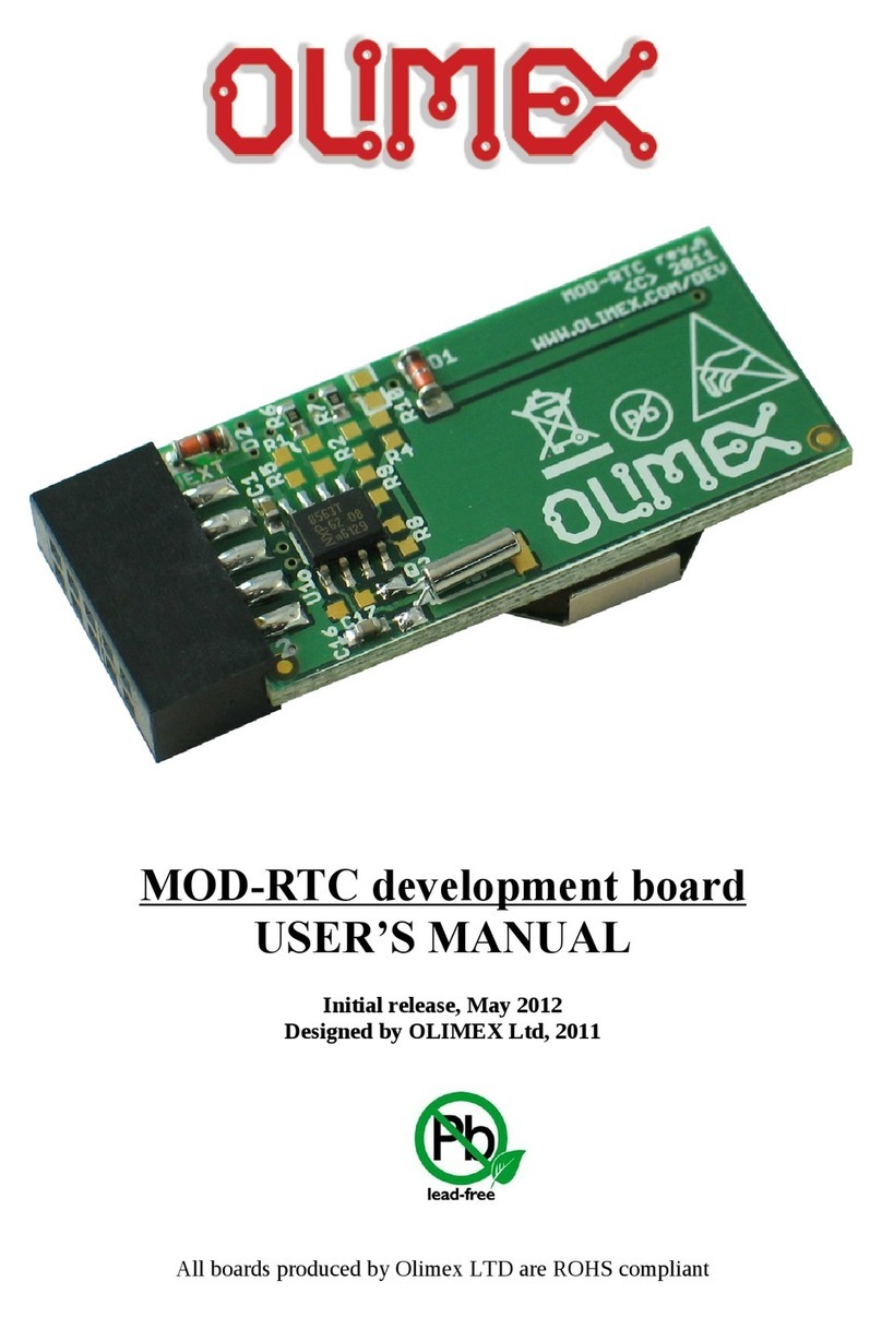
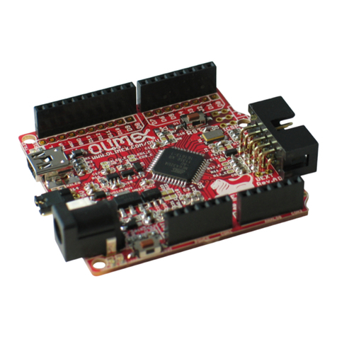
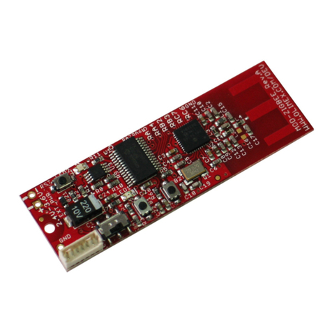
ADuC-MT7020 is small terminal board with USB link for PC, two buttons,
LCD 16x2 with backli ht and ADuC7020 with the unique 1Msps ADCs/DACs
which are accessable on separate AEXT connector.
BOARD FEATURES
–MCU: ADuC7020 - ARM7TDMI Core, 16/32-bit RISC architecture, 5
Channels 12-bit, 1MSPS ADC, Differential and sin le-ended modes, 0 to
Vref Analo Input Ran e, 4 Outputs 12-bit Volta e Output DACs, On-Chip
20ppm/°C Volta e Reference, On-Chip Temperature Sensor (±3°C),
Uncommitted Volta e Comparator, JTAG Port, Clockin options: Trimmed
On-Chip Oscillator (± 2%), External Watch crystal, External clock source
45MHz PLL with Pro rammable Divider, 62k Bytes Flash/EE Memory, 8k
Bytes SRAM, In-Circuit Download, JTAG based Debu , Software tri ered
in-circuit re-pro rammability, UART, dual I2C and SPI Serial I/O, 14-Pin
GPIO Port, 2 X General Purpose Timers, Wake-up and Watchdo Timers,
Power Supply Monitor, PLA – Pro rammable Lo ic (Array), Power
Specified for 3V operation, Active Mode: 6mW (@1MHz) 300mW
(@45MHz), Fully specified for –40°C to 85°C operation;
–JTAG connector for in-circuit pro rammin and debu in with ARM-
JTAG
–USB-RS232 convertor and interface to ADuC7020, can be used for serial
download
–I2C connector
–RESET supervisor IC and button
–SERIAL DOWNLOAD (bootloader enable) button
–Two buttons
–LCD 16x2 display with BACKLIGHT
–32 768 Hz oscillator crystal
–Power supply filterin capacitor and ferite bead
–Extension header for ADC and DAC ports
–On-chip Bootloader, which can be accessed via USB usin
ARMWSD.exe. When you open ARMWSD.exe, click button Start and after
that will be appeared messa e “Press Download and pulse Reset on
hardware” - press button SD on AduC-MT7020 and pulse Reset button –
this will ive you access to Bootloader, where you can load your own
pro ram.
–PCB: FR-4, 1.5 mm (0,062"), reen soldermask, white silkscreen component
print
Page 2
