manuals.online logo
Brands
  1. Home
  2. •
  3. Brands
  4. •
  5. OLIMEX
  6. •
  7. Motherboard
  8. •
  9. OLIMEX LPC2478-STK User manual

OLIMEX LPC2478-STK User manual

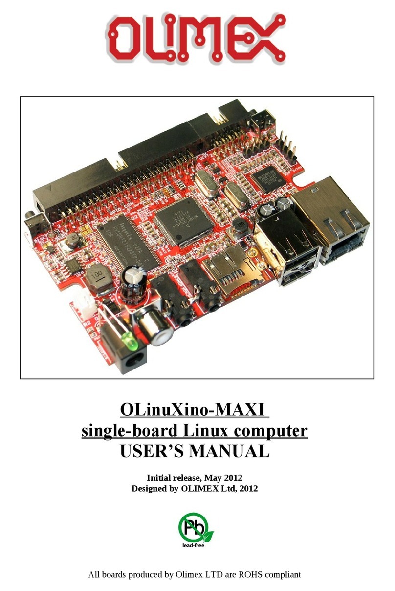
LPC2478-STK and LPC2478-STK-MICTOR
development boards
User's Man al
Doc ment revision C, October 2012
Copyright(c) 2009, OLIMEX Ltd, All rights reserved
Page 1
INTRODUCTION:
LPC-2478STK is a starter kit which uses MCU LPC2478 from NXP. This
owerful MCU su orts various serial interfaces such as USB host, USB
device, UART, CAN, etc. Additionally, you will find also audio in ut and
out ut as well as MP3 decoder, digital accelerometer, JTAG, Ethernet,
touchscreen TFT dis lay and SD/MMC card connector on this board. All this
along with the ARM7TDMI-S™ architecture and uC Linux allow you to build
a diversity of owerful a lications to be used in a wide range of situations.
BOARD FEATURES:
−MCU: LPC2478
−LCD 3.5'' 320x 240 24bit color TFT with backlight and touchscreen
−MP3 decoder DSP + codec VS1002D
−3-axis digital accelerometer with 11-bit accuracy
−64 MB SDRAM
−USB host connector
−USB device connector
−IrDA transceiver (o tional)
−MICTOR Trace connector (o tional)
−PS2 keyboard connector
−100Mbit Ethernet
−CAN driver and connector
−RS232 with ICSP control
−SD/MMC card connector
−JTAG connector
−Reset button and circuit
−2 buttons
−1 trim ot
−UEXT connector
−Audio IN
−Audio OUT
−RTC battery
−FR-4, 1.5 mm, red soldermask, com onent rint
−Dimensions: 134.6x101.5mm (5.3x4.0'')
ELECTROSTATIC WARNING:
The LPC-2478STK board is shi ed in rotective anti-static ackaging. The
board must not be subject to high electrostatic otentials. General ractice
for working with static sensitive devices should be a lied when working with
this board.
BOARD USE REQUIREMENTS:
Cables: You will need different cables de ending on the used
rogramming/debugging tool. If you use Olimex's ARM-JTAG,
you will need a LPT cable. If you use ARM-USB-OCD or ARM-
USB-TINY, you will need USB A-B cable. If you use a software
Page 2
rogrammer such as FlashMagic, you may need RS232 or other
cables.
Hardware: Programmer/Debugger – ARM-JTAG, ARM-USB-TINY or ARM-
USB-OCD or other com atible rogramming/debugging tool.
Software: The board comes re-loaded with Uboot and the CD contains
ucLinux image you can co y to USB flash disk and boot. You
can use GCC or other commercial ARM com iler if you want to
develo without ucLinux RTOS.
PROCESSOR FEATURES:
PC-2478STK board use MCU PC2478 from NXP with these features:
ARM7TDMI-S rocessor, running at u to 72 MHz.
512 kB on-chi flash rogram memory with In-System Programming
(ISP) and In-A lication Programming (IAP) ca abilities. Flash
rogram memory is on the ARM local bus for high erformance CPU
access.
98 kB on-chi SRAM includes:
- 64 kB of SRAM on the ARM local bus for high erformance CPU
access.
- 16 kB SRAM for Ethernet interface. Can also be used as general
ur ose SRAM.
- 16 kB SRAM for general ur ose DMA use also accessible by the
USB.
- 2 kB SRAM data storage owered from the RTC ower domain.
LCD controller, su orting both Su er-Twisted Nematic (STN) and
Thin-Film Transistors (TFT) dis lays.
- Dedicated DMA controller.
- Selectable dis lay resolution (u to 1024 × 768 ixels).
- Su orts u to 24-bit true-color mode.
Dual Advanced High- erformance Bus (AHB) system allows
simultaneous Ethernet DMA, USB DMA, and rogram execution from
on-chi flash with no contention.
EMC rovides su ort for asynchronous static memory devices such
as RAM, ROM and flash, as well as dynamic memories such as Single
Data Rate SDRAM.
Advanced Vectored Interru t Controller (VIC), su orting u to 32
vectored interru ts.
General Pur ose AHB DMA controller (GPDMA) that can be used with
and SD/MMC interface as well as for memory-to-memory transfers.
Serial Interfaces:
- Ethernet MAC with MII/RMII interface and associated DMA
controller. These functions reside on an inde endent AHB.
Page 3
- USB 2.0 full-s eed dual- ort device/host/OTG controller with
on-chi PHY and associated DMA controller.
- Four UARTs with fractional baud rate generation, one with
modem control I/O, one with IrDA su ort, all with FIFO.
- CAN controller with two channels.
- SPI controller.
- Two SSP controllers, with FIFO and multi- rotocol ca abilities.
One is an alternate for the SPI ort, sharing its interru t. SSPs
can be used with the GPDMA controller.
- Three I2C-bus interfaces (one with o en-drain and two with
standard ort ins).
- I2S (Inter-IC Sound) interface for digital audio in ut or out ut. It
can be used with the GPDMA.
Other eri herals:
- SD/MMC memory card interface.
- 160 General ur ose I/O ins with configurable ull-u /down
resistors.
- 10-bit ADC with in ut multi lexing among 8 ins.
- 10-bit DAC.
- Four general ur ose timers/counters with 8 ca ture in uts and
10 com are out uts. Each timer block has an external count
in ut.
- Two PWM/timer blocks with su ort for three- hase motor
control. Each PWM has an external count in uts.
- Real-Time Clock (RTC) with se arate ower domain. Clock
source can be the RTC oscillator or the APB clock.
- 2 kB SRAM owered from the RTC ower in, allowing data to be
stored when the rest of the chi is owered off.
- WatchDog Timer (WDT). The WDT can be clocked from the
internal RC oscillator, the RTC oscillator, or the APB clock.
Single 3.3 V ower su ly (3.0 V to 3.6 V).
4 MHz internal RC oscillator trimmed to 1 % accuracy that can
o tionally be used as the system clock.
Three reduced ower modes: idle, slee , and ower-down.
Four external interru t in uts configurable as edge/level sensitive. All
ins on ort 0 and ort 2 can be used as edge sensitive interru t
sources.
Processor wake-u from Power-down mode via any interru t able to
o erate during Power-down mode (includes external interru ts, RTC
interru t, USB activity, Ethernet wake-u interru t, CAN bus activity,
ort 0/2 in interru t).
Two inde endent ower needed features.
Each eri heral has its own clock divider for further ower saving.
These dividers hel reduce active ower by 20 % to 30 %.
Brownout detect with se arate thresholds for interru t and forced
reset.
Page 4
On-chi ower-on reset.
On-chi crystal oscillator with an o erating range of 1 MHz to 24
MHz.
On-chi PLL allows CPU o eration u to the maximum CPU rate
without the need for a high frequency crystal. May be run from the
main oscillator, the internal RC oscillator, or the RTC oscillator.
Boundary scan for sim lified board testing.
Versatile in function selections allow more ossibilities for using on-
chi eri heral functions.
Standard ARM test/debug interface for com atibility with existing
tools.
Emulation trace module su orts real-time trace.
Page 5
BLOCK DIAGRAM:
Page 6
MEMORY MAP:
Page 7
SCHEMATIC:
Page 8
2.5 V
2.5 V
2.5 V
2.5 V
BAT_HOL DER
10K
10 0n
10 0n
100 n
100 n
10 0n
10 0n
10 0n
10 0n
10 0n
10 0n
10 0n
22 p
22 p
10 p
10 p
10 0n
10 0n
10 0n
10 0n 100n
100 n
100uF/25V/SMD
47 0p
10 0n
220uF/10V/tnant
100 0u F/6.3V/8 1 2mm
10 0n
1n
10 0n
10 0n
18 p(NA)18 p(NA)
100 n
10 0n
47 uF/6 .3V
47 0uF/16VDC
10 0n
10 0n
10u/6.3V 1.5n
10u /6.3V 10 u/6 .3V 100n 1 00 n
2.2 uF
10u/6.3V
10u/6.3V
1u
100 n
10 0n
10 0n
10 n
10 n
10 0n
100nF
10 0n
10 0n(NA)
4.7uF/ 6.3V(NA )
47 uF/6 .3V
10u/6.3V
100 n
10 0n
10 u/6.3V10 0n
10 0n
10 uF/1 6VDC
10 0n
10u /6.3V
10 0n
10 0n
10 u/6.3V
100n
NA
10 00uF/6.3V/low_ ESR
47 uF/6 .3V
1u
47 p(N A)47 p(N A)
4.7n
2.2 uF 1 00n F
10n
10 0n 10 0n
10 0n 1 00n10 0n 100n10 0n 10 0n 10 0n
10 0n 1 00n100 n 100n10 0n
10 0n
10 0p
10 0n
33 p
33 p
10 u/6 .3V
10 0n 100n
10 n 10n 10n
10 u/6 .3V
10 u/6 .3V
10 0n
10u/6.3V
CO N33.5MM
6N C2- 50MHz
1N5819S
BAT54C
1N414 8
1N5819S
1N5822(SMC)
DB1 04(SMD)
JAC K-3PINPHONE _JAC K-TH
TFDU4 10 0(N A)
47 0nH
47 0nH
fer rite be ad
22 0uH
33 uH/CW8 A
fer rite be ad
47 0nH
470nH
10 0uH
FERR ITE_BEAD
RJL BC-0 60 TC1
JACK -3PINPHONE_JACK-TH
+5V
+20 V
+5V
+5V
+5V
+5V
+5V
+15 V
+15V
+20V
VIN
+5V
+5V
+5V
+20V
+15V
+5V
+5V
-10V
-10V
-10V
MD6R MINI-D IN
12 .00 0MHz
32 768/6p F
12 .288MHz
10 0K
10 0K
10 0K
22 0
R_ 0R( NA)
10 K
22 0
33 K
33 K
20K /1%
20 K/1%
1K
22 0
1.2 k/1 %
4.7 K
3.3 K
33
33
15 K
20 K/1%
10 0K
2.2
18 K/1%
4.7K
33
33
1.5 K/1 %
10 K
2.2 K
20 K/1%
56 0
1K
1K
20 K/1%
150
4.7K
NA
120
NA
10 K
NA
2. 2K
33 K
33 K
2.2 K
10 K 10K 10 K 10K
10 K4.7 K
1K
10 0K
1K
1K
33 K
4.7 K
10 K
4. 7K 4.7K
330 /1%
10 0/1 %
33 0/1 %
1
8.2k/1%
1.1K/1%
1K
1K
1K
1M
10 0k
10 0k
22 2 2 22
33 0/1 %
20 K/1%
1K
R_0R(NA)
NA
10 0k
10 0k
10 0K
10 K
10 0/1%
10 K(NA )
14 (NA )
47( NA)
10 K(NA )
56 0
R_0R(NA)
R_0R(NA)
22 0(NA)
15 K10 0K
4.99K/1%
150K
68 K
33
2.2 K
10 K10K
33 K
33 K
33 K
33 K
4.7 K
2. 2K
33 K
NA
NA
10 K
4. 99K/1%
1.5 K/1%
2.2 K
49 .9/1%
49 .9/1 %
49 .9/1%
49 .9/1%
33 0/1 %
33 0/1%
10 K
NA
NA
3. 3K
3.3 K
3.3 K
3.3 K
1K
1K
4.7 K
1K
33K
3.3 K
22 K
24K
NA
R_0R(NA)
NA
10 K
10 K
0
SW- TAKT1
0
db 9_male
0
re d
SD-C ARD
BC8 17
BC8 07
IRL M64 02
BC8 17
0
GFT035A32024 0Y
0
0
LPC 2478
ST3232 CD(R),(SO1 6)
MC3406 3AD(R2 )G, (SO 8)
K4S 561632C-TC/L 75
SMB3 80,(QFN10)
MC3406 3AD(R2 )G ,(SO 8)
MCP2 55 1(T)-I/SN,(SO8)
TL062C D,(SO8)
TL0 62C D,( SO8 )
KS87 21BL
VS1002
K4S 561632C-TC/L 75
LM3 526M-L,(SO8)
USB_B
yellow
USB_A
yellow
3.3 V
3.3 V
3.3 V
3.3 V
3. 3V
3. 3V
3.3 V
3. 3V
3.3 V
3.3 V
3.3 V
3.3 V
3.3 V
3.3 V
3.3 V
3. 3V
3.3 V
3.3 V
3.3 V
3.3 V
3.3 V
3.3 V
3.3 V
3. 3V
3.3 V
3. 3V
3.3 V
3.3 V
3.3 V
3. 3V
3.3 V
3.3 V
3.3 V
3.3 V
3.3 V
3.3 V
3.3 V
3.3 V
3.3 V
3.3 V
3.3 V
3.3 V
3.3 V
3.3 V
3.3 V
3. 3V
3.3 V
3. 3V
AME1085 ACDT-3Z
BD9 778 HFP
78 L15ACZ,(TO92)
#RSTOUT
#RSTOU T
#RSTOUT
#RSTOUT
#RSTOUT
#USB_O VRCR2
#USB_O VRCR2
#USB_PPWR2
#USB_PPWR2
+3.3V_A
+3.3V_A
+5V_JLIN K
+5V_JL INK
3.3 V_A
3.3 V_A
A0
A0 A0
A1
A1 A1
A2
A2 A2
A3
A3 A3
A4
A4 A4
A5
A5 A5
A6 A6
A6
A7
A7 A7
A8
A8 A8
A9
A9 A9
A10
A10 A10
A11
A11 A11
A12
A12 A12
A13
A13
A13
A14
A14
A14
ACC_INT
ACC_INT
ADC0[7 ]
ADC0[7 ]
BUT1
BUT1
BUT2
BUT2
CASN
CASN
CASN
CP
CP
CRS
CRS
CRS_DV
CRS_DV
CRS_DV
CS_ AU
CS_AU
D+
D-
D0
D0
D1
D1
D2
D2
D3
D3
D4
D4
D5
D5
D6
D6
D7
D7
D8
D8
D9
D9
D10
D10
D11
D11
D12
D12
D13
D13
D14
D14
D15
D15
D16
D16
D17
D17
D18
D18
D19
D19
D20
D20
D21
D21
D22
D22
D23
D23
D24
D24
D25
D25
D26
D26
D27
D27
D28
D28
D29
D29
D30
D30
D31
D31
DBGEN
DBGEN
DQM N0
DQM N0
DQM N1
DQM N1
DQM N2
DQM N2
DQM N3
DQM N3
DREQ
DR EQ
GBUF
GBU F
HO ST_PW R HOST_PWR
IR _RX
ISP_ E
ISP_E
KBD_C K
KBD_CK
KBD_I O
KBD_I O
LCDCP
LCDCP
LCDCP
LCDF P
LC DFP
LCDFP
LCDLP
LC DLP
LCDLP
LCD[0]
LCD[0]
LCD[1]
LCD[1]
LCD[2]
LCD[ 2]
LCD[3]
LCD[ 3]
LCD[ 4]
LCD[4]
LCD[4]
LCD[ 5]
LCD[5]
LCD[5]
LCD[ 6]
LC D[6]
LCD[6]
LCD [7]
LCD[7]
LCD[7]
LCD[8]
LCD[8]
LCD[9]
LCD[9]
LCD[10 ]
LCD[10 ]
LCD[11 ]
LC D[11 ]
LCD[12 ]
LC D[1 2]
LCD[13 ]
LC D[1 3]
LCD[14 ]
LC D[1 4]
LCD[15 ]
LCD[15 ]
LCD[16 ]
LCD[16 ]
LCD[17 ]
LCD[17 ]
LCD [18]
LCD[18 ]
LCD[19 ]
LCD [19]
LCD[20 ]
LCD[20 ]
LCD[21 ]
LCD[21 ]
LCD[22 ]
LCD[22 ]
LCD[23 ]
LCD[23 ]
LED100 /DUP
LE DACT
LEFT
LEFT
MCIC LK
MCIC LK
MCICMD
MCIC MD
MCID AT0
MCID AT0
MCID AT1
MCID AT1
MCID AT2
MCID AT2
MCIDAT3
MCIDAT3
MC IPWR
MCIPWR
MDC
MDC
MDIO
MDIO
MISO
MIS O
MIS O0
MISO 0
MOSI
MOSI
MOSI0
MOSI 0
PHY_IRQ
PHY_IRQ
PHY_I RQ
PHY_PD
PHY_PD
PIPEST AT0
PIPES TAT0
POL
POL
RASN
RASN
RASN
RD1
RD1
REFCK
REFCK
REFCK
RIGHT
RIG HT
RMII
RMII
RST
RST
RST
RST
RTCK
RTCK
RTC K
RX0
RX0
RX0
RX1
RX1
RX1
RX2
RX2
RX3
RX3
RXD 0
RXD0
RXD 2
RXD2
RXD3
RXD3
RXER
RXER
RXER
SCK
SCK
SCK0
SCK0
SCL0
SCL 0
SCL2
SCL2
SDA0
SDA0
SDA2
SDA2
SDC LK
SDCLK
SDC LK
SDC LKEN
SDC LKEN
SDC LKEN
SDC S
SDCS
SDC S
SDW EN
SDW EN
SDW EN
SSEL
SSEL
SSEL0
SSEL 0
TCK
TCK
TCK
TD1
TD1
TDI
TDI
TD I
TDO
TDO
TD O
TMS
TMS
TM S
TRACECLK
TRAC ECLK
TRAC ESYNC
TRAC ESYN C
TRACESYNC
TRSTN
TRSTN
TR STN
TX0
TX0
TX1
TX1
TXD0
TXD0
TXD 2
TXD2
TXD3
TXD3
TXEN
TXEN
U1D+
U1D+
U1D-
U1D-
U2D+
U2D +
U2 D-
U2D -
USB1_C ONNECT
USB1_C ONNECT
USB_PWRD2
USB_PWR D2
USB_UP_ LED1
USB_UP_ LED1
USB_UP_ LED2
USB_UP_ LED2
VBUS
VBUS
VCO M
VCOM
WP
WP
X1
X1
X2
X2
Y1
Y1
Y2
Y2
12
-10V_E
12
3.3 VA_E
1 2
3.3 V_E
+ -
3V_ BAT
1 2
15V _E
AN_TRIM
12
AOU T
1
2
BDS_E
BUT1 BUT2
1
2
3
C/SC
C1
C2
C3
C4
C5
C6
C7
C8
C9
C10
C11
C12
C13
C14
C15
C16
C17
C18
C19
C20
C21
C22
C23
C24
C25
C26
C27
C28
C29
C3 0
C3 1C3 2
C3 3
C34
C35
C3 6
C37 C38
C39
C40
C41 C42 C 43 C44
C4 5
C46
C47
C48
C49
C50C51
C52
C5 3
C54
C55
C56
C5 7
C58
C59
C60
C6 1
C62
C6 3C6 4
C65
C6 6
C67
C68
C6 9
C70
C71
C72
C7 3
C74
C75
C76
C77C78
C79
C80 C81
C82
C85 C86C87 C88C89 C90C 91 C92 C93C94 C95C96 C97C 98
C99
C100
C1 01
C102
C103
C104
C105 C10 6
C107 C10 8 C10 9
C110
C1 11
C112C114
1
2
3
CAN1
12
CAN1_D
12
CAN1_T
1
3
4
2
CD1
D1
D2
D4
D5
D6
1
2
ETM-E
EXT- 1
EXT- 2
EXT-3
EXT- 4
EXT-5
EXT-6
EXT-7
EXT-8
EXT- 9
EXT-1 0
EXT-1 1
EXT-1 2
EXT-1 3
EXT- 14
EXT- 15
EXT- 16
EXT-1 7
EXT-1 8
EXT-1 9
EXT- 20
1
2
3
EXT/BAT
1
2
3
EXT/JLNK
G1
GND
HEADPHO NES
12
I2S RX_SDA
GND 8
IRED _ANOD E 1
IRE D_CATH ODE 2
NC 5
RXD 4
SC 7
TX D 3
VCC1 6
IRDA
12
IRDA_L S_E
1
2
ISP_ E
1 2
3 4
5 6
7 8
9 10
11 12
13 14
15 16
17 18
19 20
JTAG
L1
L2
L3
L4
L5
L6
L7
L8
L9
L1 0
AG A G
AY A Y
COM 3
GND1
GND2
KG K G
KY K Y
NC 6
RD+ 7
RD- 8
TD+ 1
TD- 2
7575
7575
1nF/ 2kV
1
4
5
2
3
7
8
6
GREEN
YELLOW
LAN
MIC
1
2
3
PD/CTRL
11
22
33
44
55
66
NC1
NC2
SHIE LD
PS2
PWR
PWR _JACK
Q1
Q2
GND
GND_
Q3
R1
R2
R3
R4
R5
R6
R7
R8
R9
R1 0
R11
R12
R13
R14
R15
R16
R17
R18
R19
R20
R2 1
R22
R23
R24
R25
R2 6
R27
R2 8
R29
R30
R31
R32
R33
R34
R35
R36
R37
R38
R3 9
R4 0
R41
R42
R43
R44
R45
R46 R47 R 48 R49
R50R51
R52
R5 3
R5 4
R55
R5 6
R57
R5 8
R59 R60
R61
R62
R63
R64
R65R66
R67
R68
R6 9
R7 0
R71
R72
R73 R74 R75
R76
R77
R78
R79
R80
R81
R82
R8 3
R8 4
R85
R86
R87
R88
R89
R90
R91
R92
R94
R95R96
R97
R98
R9 9
R100
R108
R109R110
R111
R112
R113
R1 14
R1 15
R1 16
R117
R118
R1 19
R123
R124
R125 R1 26
R127
R128
R129
R130
R131
R132
R133
R134
R135
R1 36
R137
R138
R139
R140
R141
R142
R143
R144
R146
R147
R148
R149
R150
R1 51
R152
R1 54
12
RC
RESET
12
RS
1
2
3
4
5
6
7
8
9
G1
G2
RS232_ 0/I CSP
1
2
RST_ E
12
RW
SD
CD/DA T3/CS
1
CLK/S CLK
5
CMD/DI
2
CP1
13
CP2
15
DAT0/DO
7
DAT1/RES
8
DAT2/RES
9
VDD
4VS S1
3
VS S2
6
WP 1
10
WP 2
14
SD/ MMC
T2
T3
T4
T5
12
TC
#RES ET 6
B0
12
B1
13
B2
14
B3
15
B4
16
B5
17
B6
18
B7
19
DCLK 38
ENB 52
G0
20
G1
21
G2
22
G3
23
G4
24
G5
25
G6
26
G7
27
GND 53
HSYNC 36
M1 P1
M2 P2
NC1 5
NC2 44
NC3 46
NC4 48
PO L 7
R0
28
R1
29
R2
30
R3
31
R4
32
R5
33
R6
34
R7
35
SP CLK 49
SP DAT 50
SP ENA 43
VB L+1 3
VB L+2 4
VB L-1 1
VB L-2 2
VCC1 41
VCC2 42
VCOM 51
VDD1 39
VDD2 40
VS S 54
VS YNC 37
V_G H 47
V_G L 45
X1 9
X2 1 1
Y1 8
Y2 1 0
TFT
1
2
3
4
5
6
7
8
9
10
11
12
13
14
15
16
17
18
19
20
21
22
23
24
25
26
27
28
29
30
31
32
33
34
35
36
37
38
GND1
GND2
GND3
GND4
GND5
TRAC E
MIG TOR( NA)
12
TS
12
TW
#RES ET 35
#RST OUT 29
#TRS T 8
ALA RM
37
DBGEN 9
NC1 30
NC2 117
NC3
141
P0[0]/R D1/TXD3/SDA1
94
P0[1]/T D1/RXD3/SCL1
96
P0[2]/T XD0
202
P0[3 ]/RXD0
204
P0[4]/ I2SRX_ CLK/LCD[0]/RD 2/CAP2[0]
168
P0[5 ]/I2SRX_ WS/LCD[1]/TD2/CA P2[1]
166
P0[ 6]/I2SRX _SDA/LCD[8]/SS EL1/MA T2[0]
164
P0[7]/I2S TX_CLK/LCD[9]/S CK1/MA T2[1]
162
P0[8]/I2S TX_WS/LCD [16]/MISO 1/MAT2[2]
160
P0[9]/I2S TX_SDA/L CD[17]/MOS I1/MAT2[3]
158
P0[10]/TXD2/SDA2/MA T3[0]
98
P0[11]/R XD2/SC L2/MAT3[1]
100
P0[12]/#U SB_PPW R2/MISO 1/AD0[6]
41
P0[13]/U SB_UP_LED2/MOSI1/A D0[7]
45
P0[14]/#U SB_HSTE N2/USB _CONN ECT2/S SE L1
69
P0[15]/T XD1/SCK0/S CK
128
P0[16]/R XD1/S SEL0/SSE L
130
P0[17]/C TS1/MIS O0/MIS O
126
P0[18]/D CD1/MOS I0/MOSI
124
P0[19]/D SR1/MCICLK/SDA 1
122
P0[20]/ DTR1/MCICMD/S CL1
120
P0[2 1]/RI1/MCIPW R/RD1
118
P0[ 22]/RTS1/MC IDAT0/TD1
116
P0[2 3]/AD0[0]/I2SR X_CLK /CAP 3[0]
18
P0[24]/A D0[1]/I2SRX_WS /CAP 3[1]
16
P0[25]/A D0[2]/I2SRX_SDA /TX D3
14
P0[26]/A D0[3]/AO UT/RX D3
12
P0[27]/S DA0
50
P0[28]/S CL0
48
P0[29]/U SB_D+1
61
P0[30]/U SB_D-1
62
P0[31]/U SB_D+2
51
P1[0]/E NET_TXD0
196
P1[1]/E NET_TXD1
194
P1[2]/E NET_TXD2/MCICLK/P WM0[1]
185
P1[3]/E NET_TXD3/MCICMD/PW M0[2]
177
P1[4]/E NET_TX_E N
192
P1[5 ]/ENET_TX_E R/MCIPW R/P WM0[3]
156
P1[ 6]/ENET_TX_C LK/MCIDA T0/PW M0[4]
171
P1[ 7]/ENET_COL/MCIDAT1/P WM0[5]
153
P1[8]/E NET_C RS_DV /ENE T_CRS
190
P1[9]/E NET_R XD0
188
P1[10]/E NET_ RXD1
186
P1[11]/E NET_ RXD2/MCIDAT2/P WM0[6]
163
P1[12]/E NET _RXD3/MCIDAT3/P CAP 0[0]
157
P1[13]/E NET _RX_DV
147
P1[14]/E NET _RX_E R
184
P1[15]/E NET_REF_C LK/ENET_RX_CLK
182
P1[16]/E NET_MDC
180
P1[17]/E NET_MDIO
178
P1[18]/U SB_UP_LED 1/PW M1[1]/CAP1[0]
66
P1[19]/#USB_TX_E 1/#USB _PPWR1/CA P1[1]
68
P1[20]/U SB_TX_DP 1/LCD[6]/LCD[10]/P WM1[2]/S CK0
70
P1[21]/ USB_TX_DM1/LCD[7]/LCD[11]/PW M1[3]/SS EL0
72
P1[22 ]/USB_RCV1/LCD[8]/LCD[12]/USB _PW RD1/MAT1[0]
74
P1[2 3]/USB_RX_DP 1/LCD[9]/LCD[13]/P WM1[4]/MIS O0
76
P1[ 24]/USB_RX_DM1/LCD [10]/LCD[14]/PW M1[5]/MOS I0
78
P1[ 25]/#USB_LS1/LCD[11]/LCD[15]/#USB _HSTE N1/MAT1[1]
80
P1[26]/#US B_S SP ND1/LCD[12]/LCD[20]/PWM1[6]/CAP 0[0]
82
P1[27]/#US B_INT 1/LCD[13]/LCD[21]/#US B_O VRCR1/CAP0[1]
88
P1[28]/US B_S CL1/LCD[14]/LCD [22]/PCA P1[0]/MAT0[0]
90
P1[29]/US B_S DA1/LCD[15]/LCD[23]/PC AP1[1]/MAT0[1]
92
P1[30]/US B_P WRD 2/VBU S/AD0 [4]
42
P1[31]/#U SB_OVRCR2/SCK 1/AD0[5]
40
P2[0]/P WM1[1]/TXD1/TRA CEC LK/LCDP WR 154
P2[1]/P WM1[2]/RX D1/PIPES TAT0/LCDLE 152
P2[2]/P WM1[3]/CT S1/P IPES TAT 1/LCDCP 150
P2[3]/P WM1[4]/DC D1/PIPEST AT2/LCDFP 144
P2[4]/P WM1[5]/DS R1/TRACES YNC /LCDAC 142
P2[5]/P WM1[6]/DT R1/TRA CEP KT0/LCDLP 140
P2[6]/P CAP 1[0]/RI1/TRA CEP KT1 /LCD[0]/LCD[4] 138
P2[7]/R D2/RTS1/TRACE PK T2/LCD[1]/LCD [5] 136
P2[8]/T D2/TXD 2/TRACEPK T3/LCD[2]/LCD [6] 134
P2[9]/U SB_CONNE CT1/RXD 2/EXTIN0/LCD[3]/LCD [7] 132
P2[10]/ #EINT0 110
P2[11]/ #EINT1/LCD CLKIN/MCIDA T1/I2S TX_CLK 108
P2[1 2]/#EINT2/LC D[4]/LCD[3]/LCD[8]/LCD[18]/MCIDAT2/I2STX _WS 106
P2[ 13]/#EINT3/LC D[5]/LCD[9]/LCD[19]/MCIDAT3/I2STX_S DA 102
P2[14]/#CS 2/CAP 2[0]/SDA 1 91
P2[15]/#CS 3/CAP 2[1]/SCL1 99
P2[16]/#CA S 87
P2[17]/#RA S 95
P2[18]/CL KOUT0 59
P2[19]/CLK OUT1 67
P2[20]/#D YCS0 73
P2[21]/#D YCS1 81
P2[22]/#D YCS2/CAP3[0]/SCK 0 85
P2[23]/#D YCS3/CAP3[1]/SS EL0 64
P2[24]/C KEOUT0 53
P2[25]/C KEOUT1 54
P2[26]/C KEOUT2/MA T3[0]/MISO 0 57
P2[27]/ CKEOUT3/MA T3[1]/MOS I0 47
P2[2 8]/DQMOUT 0 49
P2[29 ]/DQMOUT 1 43
P2[3 0]/DQMOUT 2/MAT3[2]/SDA2 31
P2[ 31]/DQMOUT 3/MAT3[3]/SCL2 39
P3[0]/D0 197
P3[1]/D1 20 1
P3[2]/D2 20 7
P3[3]/D3 3
P3[4]/D4 1 3
P3[5]/D5 17
P3[6]/D 6 23
P3[7]/D 7 27
P3[8]/D 8 191
P3[9]/D 9 199
P3[10]/D 10 205
P3[11]/D 11 208
P3[12]/ D12 1
P3[1 3]/D13 7
P3[1 4]/D14 21
P3[1 5]/D15 28
P3[16]/D16/P WM0[1]/T XD1 137
P3[17]/D17/P WM0[2]/RX D1 143
P3[18]/D18/P WM0[3]/CT S1 151
P3[19]/D19/P WM0[4]/DC D1 161
P3[20]/D20 /PWM0[5]/DSR1 167
P3[21]/D 21/PWM0[6]/DTR1 175
P3[22]/D 22/PCA P0[0]/RI1 195
P3[23]/D 23/CAP 0[0]/PCA P1[0] 65
P3[24]/D 24/CAP 0[1]/PWM1[1] 58
P3[25]/D 25/MAT0[0]/P WM1[2] 56
P3[26]/D 26/MAT0[1]/P WM1[3] 55
P3[27]/D 27/CAP 1[0]/PWM1[4] 203
P3[28]/D 28/CAP 1[1]/PWM1[5] 5
P3[29]/ D29/MAT1[0]/P WM1[6] 11
P3[30]/ D30/MAT1[1]/RT S1 19
P3[3 1]/D31/MAT1[2] 25
P4[ 0]/A0 75
P4[1]/A 1 79
P4[2]/A 2 83
P4[3]/A 3 97
P4[4]/A 4 103
P4[5]/A 5 107
P4[6]/A 6 113
P4[7]/A 7 121
P4[8]/A 8 127
P4[9]/A 9 131
P4[10]/A 10 135
P4[11]/A 11 145
P4[12]/A 12 149
P4[13]/A 13 155
P4[14]/ A14 159
P4[15 ]/A15 173
P4[1 6]/A16 101
P4[1 7]/A17 104
P4[ 18]/A18 105
P4[19]/A 19 111
P4[20]/A 20/SDA 2/SCK 1 109
P4[21]/A 21/SCL2/S SE L1 115
P4[22]/A 22/TXD2/MISO1 12 3
P4[23]/A 23/RXD2 /MOSI1 129
P4[24]/#O E 183
P4[25]/#W E 179
P4[26]/B LS0 119
P4[27]/B LS1 139
P4[28]/B LS2/MA T2[0]/LCD[6]/LCD [10]/LCD[2]/TX D3 170
P4[29]/B LS3/MA T2[1]/LCD[7]/LCD [11]/LCD[3]/RX D3 176
P4[30]/#CS0 187
P4[31]/#CS1 193
RTCK 20 6
RTCX 1
34
RTCX 2
36
TCK 10
TDI 4
TDO 2
TMS 6
USB_D-2
52
VB AT
38
VDD(3V3) _1
15
VDD(3V3)_2
60
VDD(3V3)_3
71
VDD(3V3)_4
89
VDD(3V3)_5
112
VDD(3V3)_6
125
VDD(3V3)_7
146
VDD(3V3)_8
165
VDD(3V3)_9
181
VDD(3V3)_10
198
VDD(DCDC)( 3V3)_1
26
VDD(DCDC)( 3V3)_2
86
VDD(DCDC)( 3V3)_3
174
VDDA
20
VREF
24
VS SA
22
VS SCO RE1
32
VS SCO RE2
84
VS SCO RE3
172
VS SIO 1
33
VS SIO 2
63
VS SIO 3
77
VS SIO 4
93
VS SIO 5
114
VS SIO 6
133
VS SIO7
148
VS SIO8
169
VS SIO9
189
VS SIO10
200
XT AL1
44
XT AL2
46
U1
C1+
1
C1-
3
C2+
4
C2-
5
R1IN 13
R1OUT
12
R2IN 8
R2OUT
9
T1IN
11 T1OUT 14
T2IN
10 T2OUT 7
V+ 2
V- 6
U2
1516
GNDVCC
U2PWR
DC
8
FB 5
IS
7
SC 1
SE 2
TC
3
VCC
6VSS 4
U3
A0
23
A1
24
A2
25
A3
26
A4
29
A5
30
A6
31
A7
32
A8
33
A9
34
A10/ AP
22
A11
35
A12
36
BA 0
20
BA 1
21
CAS
17
CKE
37 CLK
38
CS
19
DQ 0 2
DQ1 4
DQ2 5
DQ3 7
DQ4 8
DQ5 1 0
DQ6 1 1
DQ7 13
DQ8 42
DQ9 44
DQ10 45
DQ11 47
DQ12 48
DQ13 50
DQ14 51
DQ15 53
DQMH
39 DQML
15
NC1
40
RAS
18
VDD1 1
VDD2 14
VDD3 27
VDDQ1 3
VDDQ2 9
VDDQ3 43
VDDQ4 49
VS S1 28
VS S2 41
VS S3 54
VS SQ 1 6
VS SQ 2 12
VS SQ 3 46
VS SQ 4 52
WE
16
U4
CSB 5
GND
3INT 4
NC1
1
NC2
10 SCK 6
SDI/SDA 8
SDO 7
VDD
2VDDIO
9
U5
DC
8
FB
5
IS
7
SC
1
SE
2TC 3
VCC
6VSS 4
U6
CANH
7
CANL
6
RS
8
RXD 4
TX D 1
VDD 3
VREF
5
VSS 2
U7
3
2
1
U9A
5
6
7
U9B
8 4
COL/RMII 21
CRS/RMII_BTB 22
FX SD/FX EN
34
GND1 8
GND2 12
GND3 23
GND4
35 GND5
36
GND6
39
GND7
43 GND8
44
INT/P HYAD0
25 LED0/ TES T
26 LED1/ SPD100/NFEF
27 LED2/ DUPLE X
28 LED3/ NWA YEN
29
MDC 2
MDIO 1
PD#
30
REXT
37
RST#
48
RX+
33
RX-
32
RXC 10
RXD0/PHYAD4 6
RXD1/PHY AD3 5
RXD2/PHY AD2 4
RXD3/PHY AD1 3
RXDV/CRS DV/P CS_LP BK 9
RXER/ISO 11
TX+
41
TX-
40
TXC/REFCLK 15
TXD0 17
TXD1 18
TXD2 19
TXD3 20
TXEN 16
TXER 14
VDDC 13
VDDIO1 7
VDDIO2 24
VDDPLL
47
VDDRCV
38
VDDRX
31
VDDTX
42
XI
46
XO
45
U10
AGND1 37
AGND2 40
AGND3 41
AGND4 47
AVDD1 38
AVDD2 43
AVDD3 45
DGND1
4DGND2
16 DGND3
20 DGND4
21 DGND5
22
DREQ
8
DVDD1
6DVDD2
14 DVDD3
19
GB UF 42
GP IO0/SP IBO OT
33
GP IO1
34
GP IO2/DCLK
9
GP IO3/SDA TA
10
LEF T 46
MCN 2
MCP 1
RCA P 44
RIGHT 3 9
RX 26
SCLK
28 SI
29 SO
30
TES T
32
TX 27
XT ALI
18
XT ALO
17
X\C\S\
23
X\O \S\C\/B SY NC
13
X\R\E\S\E \T\
3
U11
A0
23
A1
24
A2
25
A3
26
A4
29
A5
30
A6
31
A7
32
A8
33
A9
34
A10/ AP
22
A11
35
A12
36
BA 0
20
BA 1
21
CAS
17
CKE
37 CLK
38
CS
19
DQ 0 2
DQ1 4
DQ2 5
DQ3 7
DQ4 8
DQ5 1 0
DQ6 1 1
DQ7 13
DQ8 42
DQ9 44
DQ10 45
DQ11 47
DQ12 48
DQ13 50
DQ14 51
DQ15 53
DQMH
39 DQML
15
NC1
40
RAS
18
VDD1 1
VDD2 14
VDD3 27
VDDQ1 3
VDDQ2 9
VDDQ3 43
VDDQ4 49
VS S1 28
VS S2 41
VS S3 54
VS SQ 1 6
VS SQ 2 12
VS SQ 3 46
VS SQ 4 52
WE
16
U12
#ENA 1
#ENB 4
FLA G_A 2
FLA G_B 3
GND
6IN
7OUT_A
8
OUT_B
5
U13
UEXT-1
UEXT-2
UEXT-3
UEXT-4
UEXT-5
UEXT-6
UEXT-7
UEXT-8
UEXT-9
UEXT-10
1
2
3
4
USB_DEV
USB_D_L INK
1
2
3
4
USB_HOST
USB_H_L INK
1
VI
3VO 2
GN D/ADJ
VR1
EN/SYNC
7
FB 3
GND
4
INV 5
RT
6SW 2
VIN
1
VR2(5V )
GND
IN OUT
VR3
1 2
VREF_E
6VA C
9VD C
LPC-2478STK
Rev. B
CO PYRIGHT( C), 2009
ht tp://www.olime .com/dev
+
+
+
+
+
+
+
+
++
+
+
+
+
+
+
+
+
+
+
+
+
+
VDD
VS S OUT
E/D
1-L
2
3-R
RJ45 S IDE
1:1
1:1
GND
1-L
2
3-R
IO
NA
GN
5V
CK
NA
GND
0R
0R
0R
0R
0R
US B
SH IE L D
USB
S H IE L D
BOARD LAYOUT:
POWER SUPPLY CIRCUIT:
PC-2478STK is owered by +(9-12)VDC/6VAC a lied at the ower jack.
LPC-2478STK could also be owered by a battery (CR2032, Li, 3V) but this
battery only owers the 2KB internal SRAM and the RTC (Real Time Clock).
The consum tion of LPC-2478STK varies de ending on the su lied ower
but at +10VDC it is about 250mA.
RESET CIRCUIT:
PC-2478STK reset circuit is made with R68(47k) ull-u , ca acitor
C20(100nF) and the RST button.
CLOCK CIRCUIT:
Quartz crystal 12 MHz is connected to LPC2478 in 44 (XTAL1) and in 46
(XTAL2).
Quartz crystal 32.768 kHz is connected to LPC2478 in 34 (RTX1) and in
36 (RTX2) and su lies the internal Real Time Clock.
Page 9
JUMPER DESCRIPTION:
CAN_D
CAN Disable. If this jum er is closed, the CAN is disabled.
Default state is o en.
CAN_T
This jum er assures correct work of the CAN. At each end of the
bus it should be closed. This means that if you have only two
devices with CAN, the jum ers of both devices should be closed. If
you have more than two devices, only the two end-devices should
be closed.
Default state is closed.
-10V_E
This jum er, when closed, su lies -10 V voltage to the on board
LCD anel.
Default state is closed.
15V_E
This jum er, when closed, su lies 15 V voltage to to the on board
LCD anel.
Default state is closed.
3.3V_E
This jum er, when closed, su lies 3.3 V voltage to the VDD1-10
ins of the MCU.
Default state is closed.
3.3VA_E
This jum er, when closed, su lies 3.3 V voltage to the VDDA in
of the MCU.
Default state is closed.
VREF_E
This jum er, when closed, su lies 3.3 V reference voltage to the
VREF in of the MCU.
Default state is closed.
IRDA_ S_E
IRDA_LowS eed_Enable jum er – o ened if there is no IrDA
module or it is disabled.
Default state is o ened if your board doesn't have an IrDA
connector.
I2SRX_SDA
IrDA TX in ut in jum er – o ened if there is no IrDA module
or it is disabled.
Default state is o ened if your board doesn't have an IrDA
connector.
Page 10
AOUT
IrDA RX out ut in jum er – o ened if there is no IrDA module or
it is disabled.
Default state is o ened if your board doesn't have an IrDA
connector.
RC
This jum er, when closed, out uts the LCD[0] signal from the
PC2478 to the TFT dis lay. If it is o en, in 168 of the CP2478
is connected to EXT-4.
Default state is closed.
RW
This jum er, when closed, out uts the LCD[1] signal from the
PC2478 to the TFT dis lay. If it is o en, in 166 of the CP2478
is connected to EXT-5.
Default state is closed.
RS
This jum er, when closed, out uts the LCD[8] signal from the
PC2478 to the TFT dis lay. If it is o en, in 164 of the CP2478
is connected to EXT-6.
Default state is closed.
TC
This jum er, when closed, out uts the LCD[9] signal from the
PC2478 to the TFT dis lay. If it is o en, in 162 of the CP2478
is connected to EXT-7.
Default state is closed.
TW
This jum er, when closed, out uts the LCD[16] signal from the
PC2478 to the TFT dis lay. If it is o en, in 160 of the CP2478
is connected to EXT-8.
Default state is closed.
TS
This jum er, when closed, out uts the LCD[17] signal from the
PC2478 to the TFT dis lay. If it is o en, in 158 of the CP2478
is connected to EXT-9.
Default state is closed.
ISP_E
If you ut this jum er, you enable the ISP (In-System
Programming). This is used when you want external software to
rogram the CP2478. This jum er is used in combination with
the RST_E jum er.
Default state is o en.
RST_E
If you ut this jum er, you enable external software to control the
Reset signal to the rocessor. This is used when you want external
software to rogram the CP2478. This jum er is used in
combination with the ISP_E jum er.
Default state is o en.
Page 11
ETM_E
If you ut this jum er, you enable the MICTOR Trace connector.
Default state is o en.
BDS_E
Boundary scan enable.
Default state is o en.
C/SC
This jum er controls the USB device interface.
If 1-2 are shorted, the USB is always enabled.
If 2-3 are shorted, the USB Enable is controlled by the MCU
LPC2478 signal USB1_CONNECT.
Default state is 2-3 shorted.
PD/CTR
This jum er controls the PHY signal of the Ethernet controller.
If there is no jum er, the PHY is always enabled.
If 1-2 are shorted, the PHY is disabled
If 2-3 are shorted, the PHY is controlled by the LPC2478 signal
PHY_PD.
Default state is no jum er (o ened).
EXT/J INK
This jum er controls the JLINK +5V ower line ( in19) of the JTAG
and the +5VDC ower su ly of the board.
If 1-2 are shorted, the JLINK +5V ower line ( in19) from the JTAG
interface su lies the board with +5VDC.
If 2-3 are shorted, the board is su lied with +5VDC from the
+5VDC voltage regulator.
Default state is 2-3 shorted.
EXT/BAT
This jum er controls the VBAT signal of the LPC2478.
If 1-2 are shorted, the VBAT in is su lied by an external
battery.
If 2-3 are shorted, the VBAT in is su lied by the common
+3.3VDC ower su ly for the board.
Default state is 2-3 shorted.
Page 12
INPUT/OUTPUT:
SD/MMC ED (red) with name SD connected to SD/MMC in 4.
Power-on ED (red) with name PWR – this LED shows that +3.3V is a lied
to the board.
USB host ED (yellow) with name USB_H_ INK – connected to PC2478
in 147 (P1[13]/ENET_RX_DV).
USB device ED (yellow) with name USB_D_ INK – connected to PC2478
in 66 (P1[18]/USB_UP_LED1/PWM1[1]/CAP1[0]).
User button with name BUT1 connected to PC2478 in 67
(P2[19]/CLKOUT1).
User button with name BUT2 connected to PC2478 in 81
(P2[21]/#DYCS1).
Reset button with name RESET connected to PC2478 in 35 (#RESET).
Trimpot with name AN_TRIM connected to PC2478 in 45
(P0[13]/USB_UP_LED2/MOSI1/AD0[7]).
TFT touchscreen display – 3.5'', 320x200, 24-bit color.
Page 13
EXTERNAL CONNECTORS DESCRIPTION:
JTAG:
Pin # Signal Name Pin # Signal Name
1 +3.3V 2 +3.3V
3 TRSTN 4 GND
5 TDI 6 GND
7 TMS 8 GND
9 TCK 10 GND
11 RTCK 12 GND
13 TDO 14 GND
15 RST 16 GND
17 GND 18 GND
19 +5V_JLINK 20 GND
TDI In ut Test Data In. This is the serial data in ut for the shift
register.
TDO Out utTest Data Out. This is the serial data out ut for the shift
register. Data is shifted out of the device on the negative edge of the TCK
signal.
TMS In ut Test Mode Select. The TMS in selects the next state in the
TAP state machine.
TCK In ut Test Clock. This allows shifting of the data in, on the TMS
and TDI ins. It is a ositive edge triggered clock with the TMS and TCK
signals that define the internal state of the device.
TRSTNIn ut Test Reset N. This signal resets the JTAG controller.
RTCK Out utReturn Clock. This is a synchronization signal which the
JTAG connector uses to acknowledge it is ready to receive/transmit.
JTAG is used to to rogram and debug the MCU.
Page 14
RS232:
Pin # Signal Name
1 NC
2 RXD0
3 TXD0
4 NC
5 GND
6 RST
7 NC
8 ISP_E
9 NC
The RS232 in PC2478-STK and PC2478-STK is configured as DTE.
Note that in order to establish connection to another DTE device (e.g.
personal computer) you will need a null modem cable
TXD0 Out utTransmit Data. This is the asynchronous serial data out ut
(RS232) for the shift register on the UART controller. (This in is in ut for the
RS232 and in ut for the LPC2478)
RXD0 In ut Receive Data. This is the asynchronous serial data in ut
(RS232) for the shift register on the UART controller. (This in is out ut for the
RS232 and in ut for the LPC2478)
RST In ut Reset. When you use external software to rogram the
LPC2478, this software uses the RS232 to connect to the device and if the
jum er RST_E is ut, than through this RST in the software controls the
#RESET in of the MCU. (This in is out ut for the RS232 and in ut for the
LPC2478)
ISP_E In ut In-System Programming. If you use external software to
rogram the device, this in enables the rogramming. A re-condition to
enable ISP is the ISP_E jum er to be ut. (This in is out ut for the RS232
and in ut for the LCP2478)
Page 15
CAN:
Pin # Signal Name
1 GND
2 CANL
3 CANH
CANL and CANH are either deferential in ut, or differential out ut de ending
on the function of the MCP2551 CAN controller (receiving or transmitting
data).
Page 16
PWR:
Pin # Signal Name
1 Power Input
2 GND
The ower in ut should be +(9-12VDC)/6VAC.
A dio In:
Pin # Signal Name
1 NC
2 GND
3 MCP
MCP In ut Microphone Input. This in is in ut to the DSP codec
VS1002D.
A dio O t:
Pin # Signal Name
1 LEFT
2 GBUF
3 RIGHT
EFT Out ut eft channel output. This in is out ut for the DSP codec
VS1002D.
GBUF Out utVirtual ground for audio output, 1.23 V nominal. This in is
out ut for the DSP codec VS1002D.
RIGHT Out utRight channel output. This in is out ut for the DSP codec
VS1002D.
Page 17
EXT:
Pin # Signal Name Pin # Signal Name
1 GND 2 +3.3V
3 +5V 4 P0[4]/I2SRX_CLK/LCD
[0]/RD2/CAP2[0]
5 P0[5]/I2SRX_WS/LC
D[1]/TD2/CAP2[1]
6 P0[6]/I2SRX_SDA/LCD
[8]/SSEL1/MAT2[0]
P0[ ]/I2STX_CLK/L
CD[9]/SCK1/MAT2[1
]
8 P0[8]/I2STX_WS/LCD[
16]/MISO1/MAT2[2]
9 P0[9]/I2STX_SDA/L
CD[1 ]/MOSI1/MAT2
[3]
10 TXD3
11 RXD3 12 P4[31]/#CS1
13 P4[30]/#CS0 14 P4[2 ]/BLS1
15 P4[26]/BLS0 16 P4[24]/#OE
1 P4[1 ]/A1 18 P0[10]/TXD2/SDA2/MA
T3[0]
19 P0[11]/RXD2/SCL2/
MAT3[1]
20
Page 18
UEXT:
Pin # Signal Name
1 +3.3V
2 GND
3 TXD2
4 RXD2
5 SCL2
6 SDA2
7 MISO
8 MOSI
9 SCK
10 SSEL
USB host:
Pin # Signal Name
1 USB_PWRD2
2 U2D-
3 U2D+
4 GND
USB_PWRD2 Out ut USB Power. This signal is out ut from the rocessor
and in ut for the USB host.
U2D-, U2D+ I/O This signals form the differential in ut/out ut de ending
on the direction of the data transfer.
USB device:
Pin # Signal Name
1 VBUS
2 U1D-
3 U1D+
4 GND
Page 19
VBUS Out utUSB device ower.
U1D-, U1D+ I/O This signals form the differential in ut/out ut
de ending on the direction of the data transfer.
LAN:
Pin # Signal Name Chip Side Pin # Signal Name Chip Side
1 TD+ 5 LED100/DUP
2 TD- 6 NC
3 2.5V RD+
4 LEDACT 8 RD-
LED Color Usage
Right Yellow Activity
Left Green 100MBits/s (Half/Full duplex)
TD- Out utDifferential signal out ut. This signal is out ut from the MCU.
TD+ Out utDifferential signal out ut. This signal is out ut from the MCU.
RD- In ut Differential signal in ut. This signal is in ut for the MCU.
RD+ In ut Differential signal in ut. This signal is in ut for the MCU.
Page 20

This manual suits for next models

1

Other OLIMEX Motherboard manuals

OLIMEX A13-OLinuXino User manual

OLIMEX

OLIMEX A13-OLinuXino User manual

OLIMEX AVR-H128-CAN User manual

OLIMEX

OLIMEX AVR-H128-CAN User manual

OLIMEX MSP430- P2618 User manual

OLIMEX

OLIMEX MSP430- P2618 User manual

OLIMEX A13-OLinuXino-MICRO User manual

OLIMEX

OLIMEX A13-OLinuXino-MICRO User manual

OLIMEX STM32-P152 User manual

OLIMEX

OLIMEX STM32-P152 User manual

OLIMEX OLinuXino-MAXI User manual

OLIMEX

OLIMEX OLinuXino-MAXI User manual

OLIMEX A10-OLINUXINO-LIME User manual

OLIMEX

OLIMEX A10-OLINUXINO-LIME User manual

OLIMEX OLIMEXINO-328 User manual

OLIMEX

OLIMEX OLIMEXINO-328 User manual

OLIMEX MOD-VGA User manual

OLIMEX

OLIMEX MOD-VGA User manual

OLIMEX OLinuXino-MAXI User manual

OLIMEX

OLIMEX OLinuXino-MAXI User manual

OLIMEX A20-OLinuXino-MICRO User manual

OLIMEX

OLIMEX A20-OLinuXino-MICRO User manual

OLIMEX MOD-SD MMC User manual

OLIMEX

OLIMEX MOD-SD MMC User manual

OLIMEX AVR-ISP-MK2 User manual

OLIMEX

OLIMEX AVR-ISP-MK2 User manual

OLIMEX TMS320-XDS100-V3 User manual

OLIMEX

OLIMEX TMS320-XDS100-V3 User manual

OLIMEX OLIMEXINO-32U4 User manual

OLIMEX

OLIMEX OLIMEXINO-32U4 User manual

OLIMEX OLinuXino-MAXI User manual

OLIMEX

OLIMEX OLinuXino-MAXI User manual

OLIMEX LPC-P1227 User manual

OLIMEX

OLIMEX LPC-P1227 User manual

OLIMEX PIC32-PINGUINO-MX220 User manual

OLIMEX

OLIMEX PIC32-PINGUINO-MX220 User manual

OLIMEX SAM9-L9261 User manual

OLIMEX

OLIMEX SAM9-L9261 User manual

OLIMEX PIC-P28 User manual

OLIMEX

OLIMEX PIC-P28 User manual

OLIMEX PIC-P40-USB User manual

OLIMEX

OLIMEX PIC-P40-USB User manual

OLIMEX MSP430-CCRF User manual

OLIMEX

OLIMEX MSP430-CCRF User manual

OLIMEX AVR-ISP500-ISO User manual

OLIMEX

OLIMEX AVR-ISP500-ISO User manual

OLIMEX iMX233-OLinuXino-NANO User manual

OLIMEX

OLIMEX iMX233-OLinuXino-NANO User manual

Popular Motherboard manuals by other brands

FRONTGRADE GR740-MINI quick start guide

FRONTGRADE

FRONTGRADE GR740-MINI quick start guide

Ampro LittleBoard 735 Reference manual

Ampro

Ampro LittleBoard 735 Reference manual

Gigabyte GA-Z77P-D3 user manual

Gigabyte

Gigabyte GA-Z77P-D3 user manual

Texas Instruments BUF20800 user guide

Texas Instruments

Texas Instruments BUF20800 user guide

Enpirion EN5339QI user guide

Enpirion

Enpirion EN5339QI user guide

TYAN TIGER I7320, D, R, RD user manual

TYAN

TYAN TIGER I7320, D, R, RD user manual

Zeal-All ZA-1800MINI user manual

Zeal-All

Zeal-All ZA-1800MINI user manual

Asus Rog Maximus X Apex user manual

Asus

Asus Rog Maximus X Apex user manual

Gigabyte GA-8EGXRP Series user manual

Gigabyte

Gigabyte GA-8EGXRP Series user manual

Zotac nForce 610i - ITX user manual

Zotac

Zotac nForce 610i - ITX user manual

Gigabyte GA-8IP900 user manual

Gigabyte

Gigabyte GA-8IP900 user manual

Asus P8B-E/4L user guide

Asus

Asus P8B-E/4L user guide

TYAN S5517 User giude

TYAN

TYAN S5517 User giude

IEI Technology IMBA-9654 user manual

IEI Technology

IEI Technology IMBA-9654 user manual

IBASE Technology MB998 Series user manual

IBASE Technology

IBASE Technology MB998 Series user manual

Shuttle Spacewalker MV11 user manual

Shuttle

Shuttle Spacewalker MV11 user manual

ECS Z77H2-A3 user manual

ECS

ECS Z77H2-A3 user manual

Avalue Technology MX965GME user manual

Avalue Technology

Avalue Technology MX965GME user manual

manuals.online logo
manuals.online logoBrands
  • About & Mission
  • Contact us
  • Privacy Policy
  • Terms and Conditions

Copyright 2025 Manuals.Online. All Rights Reserved.