OLiPower LB51100 User manual

LB51100 Installation and UserManual
1
Shenzhen Olipower Energy & Automation Technology., Ltd
LB51100
Installation and User Manual
Version:V1.0

LB51100 Installation and UserManual
2
Shenzhen Olipower Energy & Automation Technology., Ltd
Statement...................................................................................................4
1Preface.....................................................................................................5
2Information in this Manual...................................................................5
2.1
About this Manual.................................................................................................................5
2.2
Use Range...............................................................................................................................5
2.3
Additional Information.........................................................................................................5
2.4
Symbol Used ..........................................................................................................................5
3Safety.......................................................................................................6
3.1
Warnings and Notification ...................................................................................................6
3.2
Safety Guidelines...................................................................................................................6
4Product Overviews.................................................................................6
4.1
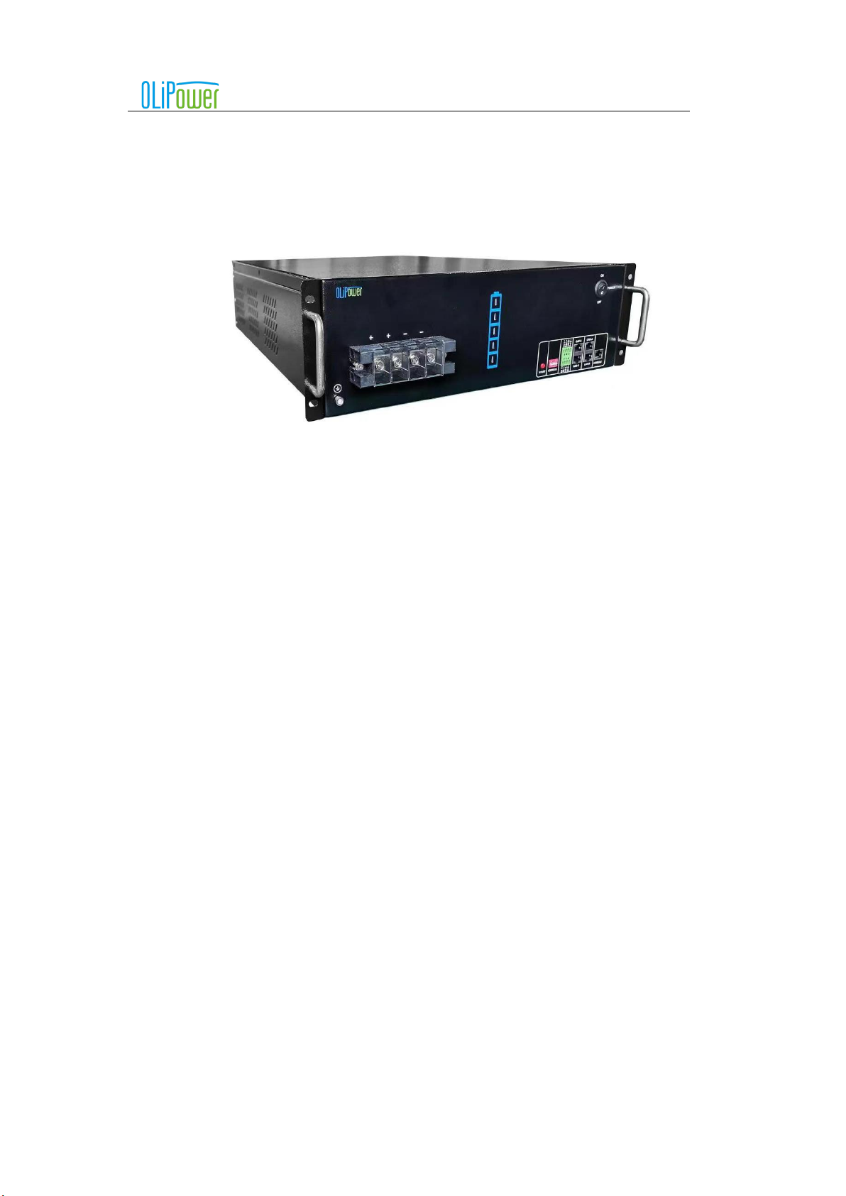
Produce Introduction............................................................................................................6
4.2
Identifying The Product .......................................................................................................6
4.3
Maintenance and Replacement............................................................................................6
5System Installation.................................................................................7
5.1
Installation notice..................................................................................................................7
5.2
Package information and system configuration list...........................................................7
5.2.1 Parts list ...................................................................................................................................................7
5.2.2 Installation Tool .......................................................................................................................................................8
5.2.3 Personal protective equipment.................................................................................................................8
5.3
Installation.............................................................................................................................8
5.3.1 Product dimensions..................................................................................................................................8
5.3.2 Installation method...................................................................................................................................8
5.4
Wiring definition...................................................................................................................9
5.4.1 Terminal function and definition..............................................................................................................9
5.4.2 A single battery box is connected to the inverter....................................................................................10
5.4.3 Multiple parallel battery boxes connected with inverter ........................................................................12

LB51100 Installation and UserManual
3
Shenzhen Olipower Energy & Automation Technology., Ltd
6Battery box activate and shutdown....................................................14
6.1
Panel buttons and LEDs meaning .....................................................................................14
6.2
The operation steps of the battery box works alone.........................................................14
6.2.1 Start battery box.....................................................................................................................................14
6.2.2 Shut down battery box...........................................................................................................................14
6.2.3 Low battery forced charge function .......................................................................................................15
6.3
The steps of the battery boxes work in parallel................................................................15

LB51100 Installation and UserManual
4
Shenzhen Olipower Energy & Automation Technology., Ltd
Statement:
This product is low voltage (48V) residential rack battery from Shenzhen Olipower Energy & Automation
Technology., Ltd
Due to product upgrades or other reasons, this document will make appropriate adjustments. Unless otherwise
agreed, this document is intended to be used only as a guide, and all statements, information and advice in the
documentation shall not constitute any express or implied.
For more information, please contact us.

LB51100 Installation and UserManual
5
Shenzhen Olipower Energy & Automation Technology., Ltd
1Preface
Thank you for choosing our low voltage (48V) residential rack battery . We will provide you good quality as well
as reliable after service.
To protect using staffs and product, please kindly read this manual carefully which provide detailed information for
products’ features, structures, operate standard, maintenance and troubleshooting.
Special announcement:
This manual can’t be taken as basis of requirement for Olipower.
Olipower hold the final explanation right of this manual.
2Information in this Manual
2.1 About this Manual
This is the Manual for the low voltage (48V) residential rack battery products. User of this device or installer must
refer to the installation guidance to installation and using correctly.
2.2 Use Range
This installation guidance applies only to our low voltage (48V) residential rack battery products.
2.3 Additional Information
Specification of the product can be changed without any notice to customers for the system improvement.
2.4 Symbol Used
Symbols meanings:
CAUTION:
CAUTION represents hazardous situations that can cause minor damage to the equipment or personal
injury if not avoided.
NOTICE:
NOTICE represents the situations, which can cause damage the performance of the productif not
avoided.
INFORMATION:
INFORMATION provides tips that are valuable for optimum installation and operation of the product.

LB51100 Installation and UserManual
6
Shenzhen Olipower Energy & Automation Technology., Ltd
3Safety
3.1 Warnings and Notification
Installation environment requirements: low voltage (48V) residential rack battery are designed for household use.
For installation, it must be installed in a location complying with IP20. If the Installation location does not comply
with IP20 may cause failure and the product will not be guaranteed for any related accident or damage.
3.2 Safety Guidelines
CAUTION:
Install and use to avoid short-circuit between the anode terminal and a cathode terminal, all electrical connections
on the low voltage (48V) residential rack battery work must be operated by qualified professional personnel, when
operated in accordance with the expected design low voltage (48V) residential rack battery will be used as a safe
and reliable power supply. In the absence of proper operating conditions, damage, misuse and / or abuse case,
battery box there may be security risks such as overheating or electrolyte smoke potential, users are described in
this section must comply with the safety precautions and warnings. If any of the following precautions is not fully
understood or has any problems, please contact the customer service officer for assistance. The safety part may
not include all the regulations in your area. The use of low voltage (48V) residential rack battery must review
applicable local laws and regulations and the industry standards of the product.
Installation personnel shall not wear watches and other metal items to install operations, in order to avoid short
circuits and personal injuries.
CAUTION:
Due to high weight of battery pack, please use original package and do safety protection when second transport.
Please ensure that the battery box in the process of transportation safety, to avoid damage to the product and
personnel injury.
4Product Overviews
4.1 Produce Introduction
low voltage (48V) residential rack battery products as the energy storage parts can be used in off-grid & on-grid
energy storage system. It is recommended not to use this device for other than the purpose described in this
guidance. The substitute use of this product, random change, and use of components other than sold or
recommended by Olipower will nullify the product guarantee.
4.2 Identifying The Product
Battery model
Specification parameter
Matched inverter
LB51100
51.2V/5.12KWh
3.2kW
Detailed data are shown in appendix 1
4.3 Maintenance and Replacement

LB51100 Installation and UserManual
7
Shenzhen Olipower Energy & Automation Technology., Ltd
High voltage may cause an electric shock, which results in serious injury,
death, or serious property damage from the LB51100 in operation. Prior to maintenance, power off
the LB51100 and strictly comply with the safety precautions in this document and associated
documents to operate the LB51100.
Maintain the LB51100 with sufficient knowledge of this document, proper
tools, and testing equipment.
Before performing maintenance tasks, power off the LB51100 and wait at least
5 minutes.
Temporary warning signs or fences must be placed to prevent unauthorized
people from entering the site.
If the LB51100 is faulty, contact your supplier.
The LB51100 can be powered on only after all faults are rectified. Failing to do so
may escalate faults or damage the device.
Observe ESD precautions and wear ESD gloves during maintenance.
Regular Maintenance
Items
Time
Cleaning case using soft cloth
Once 6 months
Cleaning ventilation hole using soft brush
Once a year
Discharge to SOH 50% when not to use in 3month
On demand
Fully charge discharge to SOH 25%
Once a year
Disposal
The battery energy storage system must not be disposed of with domestic waste to
fulfill the regulations and legal enquiry. The user has the responsibility and
obligation to send it to the designated organization for recycling and disposal.
5System Installation
5.1 Installation notice
a) Before installation, check the battery open circuit voltage.
b) Battery installation location should be away from heat and avoid produce spark. The safety distance should be
above than 0.5m.
c) Battery installing connecting cables should be as short as possible, to prevent excessive line pressure drop.
d) Batteries with different capacity, different P/N or different manufactures are not allowed forconnection.
e) Before conducting the battery, the battery positive and negative poles need to be carefully checked as well to
ensure correct installation.
f) The mounting floor should be horizontal.
g)The battery IP Rating is IP20 and is for indoor installations only.
h)For Australian market, the battery energy storage system can only be mounted into battery cabinet or rack using screw firmed
tightly and racks can be stand together without space. And distance between batteries is 5mm as least. Battery cabinets/racks
are not provided with battery and are outside the scope of product certification.
i) Distances of any standoff from a wall, floor, ceiling/roof is 0.5m at least; Distance from any heat source (e.g. hot water
systems, gas heaters or the like) is 0.5m at least; Distance/clearances from any equipment/wall/structure to the sides, bottom,

LB51100 Installation and UserManual
8
Shenzhen Olipower Energy & Automation Technology., Ltd
top is 0.5m at least; Clearance distances from any vents to any wall, other equipment, structure is 0.5m at least.
5.2 Package information and system configuration list
The battery box is packed in cartons, and the components assort with the battery case. When you confirm the good
s, please read the configuration list carefully to make sure that the battery box and kit are intact.
5.2.1
Parts list
No.
Name
Quantity
Description
1
Battery box
1
2
Fixed screw
4
3
CAN cable
1
4
LINK cable
1
5
RS232 cable
1
6
Power cable
1set
1positive&1 negative
7
Grounding cable
1
8
Outgoing Inspection Report
1
5.2.2
Installation
Tool
5.2.3
Personal protective equipment
5.3 Installation

LB51100 Installation and UserManual
9
Shenzhen Olipower Energy & Automation Technology., Ltd
5.3.1
Product dimensions
See Appendix 2.
5.3.2
Installation method
5.3.2.1 Cabinet Installation
The positions of bolts are shown in the picture, which are anchored into ground.
5.3.2.2 Rack mounting Installation.
After the Cabinets installed firmly and reliably, the battery box is pushed from side to side along the wall until
the mounting card on the battery box is placed in the proper position of the rack mounting position.
Information:
Rack -mounted installation is suggested that the external connection line of the battery box should be connected
first and then installed.
Information: When installing the battery box, please work together to avoid product damage or
personal injury.
5.4 Wiring definition
5.4.1
Terminal function and definition
The bottom terminal layout is shown in the following figure:
Power Butten
B+,B+,B-,B-
CAN A /B
ADD&IO port
LINK A /B
COM
Grounding port
LED

LB51100 Installation and UserManual
10
Shenzhen Olipower Energy & Automation Technology., Ltd
Interface
Function
DIN1-P
IO port, interacts with a diesel engine, a photovoltaic device, or other external
device.
DIN1-N
DIN2-P
DIN2-N
DO1-P
DO1-N
SDO1-P
SDO1-N
CAN-A/B
CAN bus interface communicate with the inverter.
ADD
DIP switch, set the LINK address and terminal resistance.
B+
Battery positive (The two positives are the same, one of which can be used as a
parallel battery)
B+
B-
Battery negative (The two negative are the same, one of which can be used as a
parallel battery)
B-
Attention:B interface RJ45 port corresponding to the CAN bus pin definition
RJ45 pin number reference schematic:
5.4.2
A single battery box is connected to the inverter
5.4.2.1 The steps of a single battery box connected with the inverter
Step 1: Check the battery box enclosure is not damage.
Step 2: When the battery is not connected to the inverter, start the battery box, then confirm that the battery
box running indicator light is bright, the battery box fault indicator light is not bright, and the battery box voltage

LB51100 Installation and UserManual
11
Shenzhen Olipower Energy & Automation Technology., Ltd
output is normal. Do the next operation if there is no problem.
Step 3: Turn off the battery, then connect the communication line and power cable (connect the way to refer to
the 5.4.2.2 schematic diagram), set the DIP switch correctly, confirm the connection is correct, then turn on the
battery.
5.4.2.2 Schematic diagram of single battery box and inverter connection
Attention: The drawing is for reference only, please take the material as the standard.
It is an Australia installation standard requirement AS/NZS 5139 that an overcurrent protection and isolation device that
operates both positive and negative conductors is required between battery and inverter and also between parallel batteries.
Step 1 Connect the grounding cable to the grounding port.
Step 2 Connect the power cables to the B+ and B- tightly using screwdriver.
Step 3 Plug the CAN cable into the CAN A or CAN B port, and then connect to Inverter. Shown as following:
A single battery box through the CAN communication connection inverter when the DIP switch is defined as follows:

LB51100 Installation and UserManual
12
Shenzhen Olipower Energy & Automation Technology., Ltd
CAUTION:Set the DIP switch after the need to restart the battery box, restart the settings will
take effect.
Single battery box through the LINK communication connection to the inverter when the address DIP switch
defined as follows:
CAUTION:Set the DIP switch after the need to restart the battery box, restart the settings will
take effect.

LB51100 Installation and UserManual
13
Shenzhen Olipower Energy & Automation Technology., Ltd
5.4.3
Multiple parallel battery boxes connected with inverter
5.4.3.1 The steps of parallel connection of multiple battery boxes
Step 1: Every single battery is started and the total voltage of the battery is measured with a multimeter. It is
confirmed that the difference between the total voltage of each battery is not more than 2V, and then the following
work is carried out.
Step 2: Connect the battery box communication line, set the DIP switch (the connection of the communication line
and the setting of the dial code switch reference 5.4.3.3 description). Start Master battery box, then slave battery
box 1, and the slave battery box 2,3,…observe the state of the alarm light from the battery box. If the fault light is
on, please check whether the connection is tight enough and the switch setting is right. If the fault lights are not
bright, follow up.
Step 3: First turn off all the battery boxes, then connect the battery box power cables (the connection of power cable
to 5.4.3.4 description). After the connection is completed, start the master battery box, slave battery box 1 and slave
battery box 2 (if have slave battery box 2).
Step 4: After the battery is completed in parallel, it is suggested that you wait a few minutes to connect the inverter
later.
5.4.3.2 The connection between the parallel battery box and the inverter
Step 1: After the battery box is properly parallel, turn off all the battery boxes.
Step 2: Connect the CAN communication line between the battery box main station and the inverter (the
connection of the communication line is described by 5.4.3.3), then connect the power cable between the parallel
battery boxes and the inverter (the connection of the power cable is described by 5.4.3.4).
Step 3: Start the main station, the slave station 1, and the slave station 2 (if have slave station 2).
5.4.3.3 System communication line connection
Information: When multiple battery boxes are used in parallel, the parallel battery box and
inverter can only communicate through CAN interface, and the communication between the battery box through
LINK.
Attention: The following figure is only the communication line connection diagram.Specific interfaces must be
compared to physical objects.
It is an Australia installation standard requirement AS/NZS 5139 that an overcurrent protection and isolation
device that operates both positive and negative conductors is required between battery and inverter and also
between parallel batteries.

LB51100 Installation and UserManual
14
Shenzhen Olipower Energy & Automation Technology., Ltd
Two battery boxes in parallel when the DIP switch is defined as follows:
CAUTION:Set the DIP switch after the need to restart the battery box, restart the settings will
take effect.
Three battery boxes in parallel when the DIP switch is defined as follows:
CAUTION:Set the DIP switch after the need to restart the battery box, restart the settings will
take effect.

LB51100 Installation and UserManual
15
Shenzhen Olipower Energy & Automation Technology., Ltd
5.4.4.4 Power cable connection
Attention: The following figure is only the power cable connection diagram, the specific connection. Please
refer to the object for specific connection.
6Battery box activate and shutdown
6.1 Panel buttons and LEDs meaning
Attention: the drawing is for reference only, please take the material as the standard.
Name
Meaning
Function or indication status
ON/OFF
Turn on or off button
Control battery box on or off
RUN
Running indicator light (green)
When the battery box is running normally, it always
bright
LOW BAT
Low battery indicator (yellow)
When the battery is low(SOC<5%), it is always bright.
FAULT
Fault indicator light (red)
Flashing alarm when the battery box is faulty
6.2 The operation steps of the battery box works alone
6.2.1
Start battery box
Short press the power button (1S), RUN light on, switch on the isolator between the battery and inverter., battery box is
activated normally.
6.2.2
Shut down battery box
Long press the power button (5S), RUN light off, switch on the isolator between the battery and inverter, battery box is shut

LB51100 Installation and UserManual
16
Shenzhen Olipower Energy & Automation Technology., Ltd
down normally.
6.2.3
Low battery forced charge function
Prerequisite: When the battery voltage is too low, it will go into the shutdown state automatically. Meanwhile, the
voltage between the battery box B + and B- is zero and the panel lights are off. when push the power button, the
battery run(green) LED is on ,low battery(yellow) LED is on, fault(red) LED is flashing, if the fault(red) LED still
flashing after 3 minutes, means the battery into ultra-low battery, in ultra-low power to recharge battery can only
use forced charge function.
Preparation condition before forced charging: Connect the charger or the inverter with charging capability to the
B+ and B- of the battery box to ensure charging capacity.
Forced charging step:
Step 1: Make sure the battery is in ultra-low power, please refer to "Prerequisites".
Step 2: If the battery is off, please turn on the battery and observe whether the status of the battery indicator is
run(green) LED is on, the low power(yellow) LED is on, the fault(red) LED is flashing. if it is ,do next step operating.
(If no operation is performed for five minutes from the moment you push the power button, the battery will turn off
again.)
Step 3: Push the power button (1-2S) again, if the run(green) LED is flashing, the low power(yellow) LED is on,
the fault(red) LED is on, means the battery into forces charge state.
Step 4: After entering the forced charge state, you have 90S of time to prepare for charging. battery is detected
charging during this 90S, the fault (red) is off, run LED no longer flashing (just on) after 90S, means the battery into
the normal charging mode. the battery is not detected charging after 90S,the fault(red) LED will flashing, the battery
cannot be recharged in this time, you can only start the forced charging operation from the beginning (if no operation
within 5 minutes, the battery will enter the shutdown state).
6.3 The steps of the battery boxes work in parallel
6.3.1
Cautions before Parallel:
(1) The battery boxes voltage difference must not be greater than 2V.Otherwise, the battery boxes are not
allowed for parallel connection.
(2) The connection between the battery boxes and the parallel box is ready.
(3) Before activity the system, operator should check the cable connection strictly till make sure of the LINK
cable connection is hard, and check the batteries DIP switch had been setupcorrectly.
6.3.2
Activate the parallel batteries system
Step 1, short press the master battery box power button(1S), the master battery box RUN light on, the master
battery box is activated.
Step 2, short press the slave battery box 1 power button (1S), the slave battery box 1 RUN light on, the slave
battery box 1 is activated.
Step 3, If parallel with three battery boxes, please short press slave battery box 2 power button(1S), the slave
battery box 2 RUN light on, the slave battery box 2 is activated. Switch on dc isolators between battery and
inverter, and between batteries.
Finally, all battery boxes are activated, and the parallel batteries system is properly powered on.
6.3.3
The parallel Batteries system shutdown
Switch off dc isolators between battery and inverter, and between batteries. Long press the master battery box
power button (5s), the master battery box RUN light immediately extinguished, slave battery boxes RUN lights

LB51100 Installation and UserManual
17
Shenzhen Olipower Energy & Automation Technology., Ltd
will not be extinguished immediately. Slave battery boxes fault lights
flashing after 10s, slave battery boxes RUN lights and fault lights extinguished after 1min, the parallel Batteries
system shut down in normal.
NOTICE:
When the battery box is in parallel, press the power button of the battery box will shut down the battery box. In
normal use, we strongly recommend that you do not only turn off a battery box as a slave machine.The remote
monitoring of battery is available via inverter monitoring solution.
7Battery box abnormal and solution
Abnormal
description
Abnormal
interpretation
Phenomenon
Cause
solution
Run indicator
light,
Fault indicator
light, battery
no voltage
output
Function
of
battery
self-
protection
The low battery indicator
is light, and the fault
indicator is light. The
battery box has no
output.
The battery is too low
The battery must be charged at once, and the
specific operation will refer to the low power
charge function.
Check the communication between the battery
box and the inverter is
normal.
When the battery box is
running, fault indicator
lights up.
The battery is too
high
The battery must be stopped charging
immediately.
Check the communication between
the battery box and the inverter is normal.
The current is too
large
Please refer to the parameters of the battery
charging current and discharge current of the
corresponding model, and compare the
technical parameters of the
inverter.
The temperature is too
high
Please install the battery in a ventilated
place, which is beneficial
to the heat dissipation of thebattery.
The temperature is too
low
Please pay attention to the battery
box to keep warm in the cold area.
Incorrect
use of
battery
After starting, the fault
indicator is light.
Incorrect setting of
DIP switch
Check whether the battery box DIP switch is
set correctly. If it is not correct, please refer
to the use
manual to set the DIP switch.
When the battery is used
in parallel, the fault
indicator of the slave
station battery box is light,
and there is no
fault when the battery
Incorrect setting of
DIP switch
Check whether the communication
connection between the main and slave
stations of the battery box is firmly
connected. Check whether the DIP switch
of the battery main
station and the slave station is set

LB51100 Installation and UserManual
18
Shenzhen Olipower Energy & Automation Technology., Ltd
box is used alone.
correctly. If incorrect, please refer
to the manual to set up the DIP
switch.
When the battery box is
in parallel for the first
time, start the parallel
system. The fault
indicator of the slave
station battery box is
light, and the slave
station has no voltage
output.
Protection measures
to prevent battery
damage when the
battery is in parallel.
Take the positive and negative
voltage of each battery box. If the
voltage difference between the
battery boxes is more than 2V,
please keep the pressure difference
under 2V and try the parallel
connection.
Run indicator
light,
Fault indicator
not light,
battery no
voltage output
Battery device
damage
The battery has no fault
alarm, but there is no
voltage output
Short circuit cause
damage of battery box
fuse
Check whether the connection is
correct and whether there is a short
circuit. If there is a short circuit,
please check the cause as soon as
possible and solve the short circuit
problem, and then change the fuse
with the after sale or professional.
Battery internal
device damage
Please contact the after-sale service
Press the
battery button,
all the battery
indicators are
not light
The battery indicator is
not light and the battery
has voltage output
The battery indicator
is damaged, the line is
loose, or aging.
Please contact the after-sale service
The battery indicator is
not light and the battery
has no voltage output
Circuit board fault,
circuit board wiring
looseness or aging.
Please contact the after-sale service
Other
anomalies
Please contact the after-sale service
8Battery box compatible with the inverter
Serial
number
Inverter brand
Inverter model
1
SMA
Sunny Island
2
SolaX
X-Hybrid
3
Goodwe
ES-series
4
SofarSolar
ME 3000SP
5
MUST
PH&PV series

LB51100 Installation and UserManual
19
Shenzhen Olipower Energy & Automation Technology., Ltd
Appendix 1- Product data sheet
Product model
LB51100
ated voltage
51.2V
working voltage
44.8-58.4V
Rated capacity
100Ah
Battery energy
5.12kWh
Rated output power
3.2kW
Peak output power
5kW
Maximum continuous charging current
100A
Maximum continuous discharge
current
100A
Size(W*H*D)
440*135*620mm
weight
46.2kg
Installation method
Rack mounting
Cycle times (80% DOD,25℃)
4000
Charge temperature range
0-55℃
Discharge temperature range
-20-55℃
communication interface
CAN2.0/LINK Modbus/RS485
Battery protection
Over charge / over discharge / over temperature / over current / short
circuit
Precharge control
optional
Life time
10 years
Storage time (-20℃~35℃)
3 months
Operating environment temperature
range
0-45℃
Storage temperature range
-10-40℃
EMC standard
IEC 61000
Warranty period
5 years,4000cycles
Protection grade
IP20
Support inverter interaction protocol
SMA/Solax/GoodWe/SofarSolar/Studer/MUST

LB51100 Installation and UserManual
20
Shenzhen Olipower Energy & Automation Technology., Ltd
Appendix 2- Product size table
Product
model
Outline dimension
LB51100
Table of contents
Popular Camera Accessories manuals by other brands

Westfalia
Westfalia 36 98 27 instruction manual

Selectronic
Selectronic SP PRO 2i Series Installation note

Rollei
Rollei V6i user manual

SOMFY
SOMFY Cord Lift WireFree TL25 Quick programming guide

electroVolt
electroVolt LiONCore Series manual

Spectrum Industries
Spectrum Industries 37108 Assembly instructions

Mid-Continent Instrument
Mid-Continent Instrument True Blue Power TB20 Series Installation manual and operating instructions

Olympus
Olympus PT PT-036 instruction manual

Vividia
Vividia GB-460 user manual

GNB
GNB EPzS Series Instructions for use

PASCO
PASCO PS-3218 Replacement instructions

Ikelite
Ikelite 6110.91 instruction manual