OLiPower BRE-I-5K User manual

1
User Manual
BRE‐I‐5K
OLIPOWERENERGY&AUTOMATIONTECHNOLOGY

2
Contents
1. About This Manual ........................................................................................................................ 5
1.1Applicability.............................................................................................................................................................. 5
1.2Target group............................................................................................................................................................ 5
1.3Symbols used .......................................................................................................................................................... 5
2. Safety ................................................................................................................................................ 6
2.1General Safety ......................................................................................................................................................... 6
2.2Important safety instructions................................................................................................................................ 6
2.3Explanation of symbols.......................................................................................................................................... 7
3. Introduction ............................................................................................................................... 8
3.1Basic features........................................................................................................................................................... 8
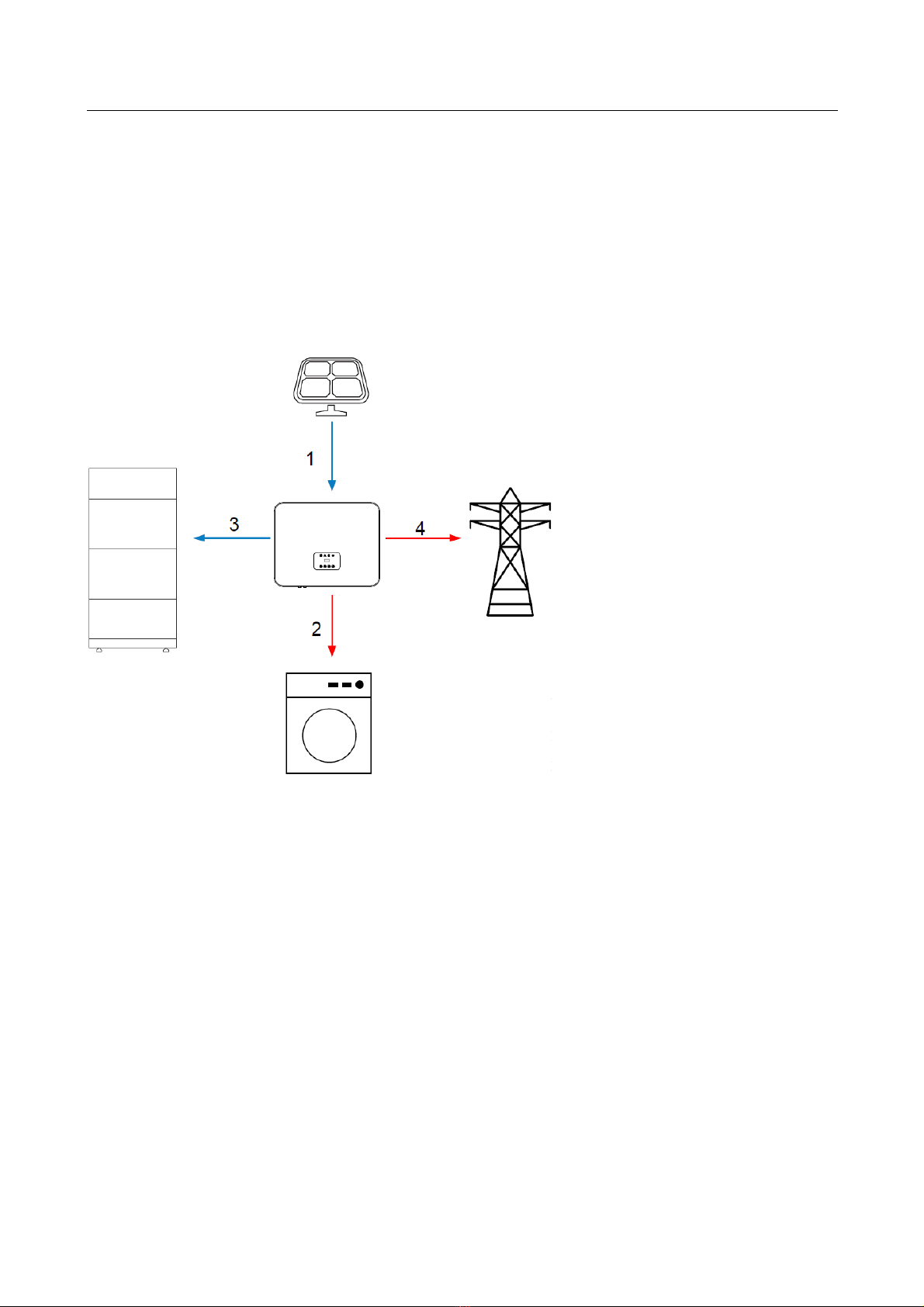
3.2Work modes ............................................................................................................................................................ 9
3.3Terminals ................................................................................................................................................................ 12
3.4Dimensions............................................................................................................................................................. 13
4. Technical data............................................................................................................................... 13
5. Installation ..................................................................................................................................... 15
5.1Unpacking .............................................................................................................................................................. 15
5.2Check for transport damage .............................................................................................................................. 16
5.3Installation precaution ......................................................................................................................................... 16
5.4Available space...................................................................................................................................................... 17
5.5Preparation............................................................................................................................................................. 17
5.6Installation steps ................................................................................................................................................... 19
5.7Electrical Wiring Connection............................................................................................................................... 20
5.7.1PV Wiring Connection.......................................................................................................................................... 22
5.7.2Battery Connection............................................................................................................................................... 23
5.7.3AC Output Connection ........................................................................................................................................ 25
5.7.4Earth connection................................................................................................................................................... 27
5.7.5Communication connection................................................................................................................................ 27
5.8Inverter manipulation........................................................................................................................................... 30

3
6. Operation Method .................................................................................................................. 32
6.1Control panel......................................................................................................................................................... 32
6.2LCD function.......................................................................................................................................................... 32
6.3LCD operation ....................................................................................................................................................... 35
6.3.1Main screen............................................................................................................................................................ 35
6.3.2Status ...................................................................................................................................................................... 35
6.3.3History..................................................................................................................................................................... 41
6.3.4Settings ................................................................................................................................................................... 41
6.3.5System Switch........................................................................................................................................................ 51
6.3.6About ...................................................................................................................................................................... 52
6.4Advanced settings ................................................................................................................................................ 52
7. Troubleshooting ...................................................................................................................... 56
7.1Troubleshooting.................................................................................................................................................... 57
7.2Maintenance .......................................................................................................................................................... 59
8. Decommissioning ................................................................................................................... 60
8.1Remove the inverter............................................................................................................................................. 60
8.2Packaging ............................................................................................................................................................... 60
8.3Storage.................................................................................................................................................................... 60
8.4Disposal .................................................................................................................................................................. 60

4
Notice
Thismanualcontainsimportantsafetyinstructionsthatmustbefollowedduringinstallationand
maintenanceoftheequipment
Save the manual!
Thismanualmustbestoredcarefullyandbealwaysavailable.

5
1. About This Manual
1.1 Applicability
Please read the product manual carefully before installation, operation, or maintenance. This
manual contains important safety instructions and installation instructions that must be
followed during installation and maintenance of the equipment.
1.2 Target group
This manual is intended for qualified electrical personal who are responsible for hybrid
inverter installation and commissioning in the storge system.
1.3 Symbols used
The following types of safety instructions and general information appear in this
document as described below
DANGER!
“Danger” indicates a hazard with a high level of risk that, if not
avoided, will result in death or serious injury.
WARNING!
“Warning” indicates a hazard with a medium level of risk that, if not
avoided, will result in death or serious injury.
CAUTION!
“Caution” Indicates a hazard with a low level of risk that, if not
avoided, could result in minor or moderate injury.
NOTICE
NOTICE!
“Notice” Indicates a situation that, if not avoided, could result in
equipment or property damage.
NOTE!
“Note” provides tips that are valuable for the optimal operation of
your product.

6
2. Safety
2.1 General Safety
The hybrid inverter has been designed and tested strictly according to international
safety regulations. Read all safety instructions carefully prior to any work and always
observe them when working on or with the hybrid inverter. Incorrect operation or work
may cause:
Injury or death to the operator or a third party;
Damage to the inverter or other properties.
2.2 Important safety instructions
DANGER
!
PV strings will produce electrical power when exposed to
sunlight and can cause a lethal voltage and an electric shock
Only qualified personnel can perform the wiring of the PV panels.
Do not open the enclosure when the inverter is running.
Unauthorized opening will void warranty and warranty claims
and, in most cases, terminate the operating license.
When the enclosure lid is removed, live components can be
touched which can result in death or serious injury due to electri
c
shock
Operating a damaged inverter can lead to hazardous situations
that can result in death or serious due to electric shock
Batteries deliver electric power, resulting in burns or a fire hazard
when they are short circuited, or wrongly installed.
Lethal voltages are present at the battery terminals and cables
connecting to the inverter. Severe injuries or death may occur i
f
the cables and terminals in the inverter are touched.
PV negative (PV-) and battery negative (BAT-) on inverter side is
not grounded as default design. Connecting PV- or BAT- to
EARTH are strictly forbidden.
WARNING
!
Do not disconnect PV connectors, AC connector or battery
connectors while the inverter is running. De-energize from all
multiple power sources. Wait 5 minutes for the internal
capacitors to discharge. Verify that there is no voltage or
current before disconnecting any connectors. Use personal
protective equipment, including rubber gloves and protective
boots durin
g
the installation or maintenance.
CAUTION
!
Do not touch any hot parts(such as the heat sink) during
operation, The temperature of inverter surface might exceed
60℃during working

7
NOTICE
CAUTION!
Electrical installation and maintenance must be carried out by
competent electricians according to local regulations.
Do not open inverter cover or change any components withou
t
OliPower’s authorization, otherwise the warranty commitmen
t
for the inverter will be invalid
Usage and operation of the inverter must follow instructions in
this user manual, otherwise the protection design might be
useless and warrant
y
for the inverter will be invalid.
NOTE!
Electrical installation and maintenance must be carried out by
competent electricians according to local regulations.
The inverter built-in RCMU will exclude possibility of DC residual
current to 6mA, thus in the system an external RCD(type A) can be
used(30mA).
Anti‐IslandingEffect
Islanding effect is a special phenomenon that arid-connected PV system still
supply power to the nearby grid when the voltage loss is happened in the power
system. it’s dangerous for maintenance personnel and the public.
BRE-I-5K hybrid inverter provide Frequency shift to prevent islanding effect.
2.3 Explanation of symbols
This section explains all the symbols shown on the type label.
Symbols on the Type Label
Symbol
Explanation
CE mark. The inverter complies with the requirements of the
applicable CE guidelines
Beware of hot surface.
The inverter can become hot during operation. Avoid contact
during operation.
Danger of high voltages.
Danger to life due to high voltages in the inverter!
Danger.
Risk of electric shock!
The inverter cannot be disposed of together with the
household waste. Disposal information can be found in
the enclosed documentation.
Don't work on this inverter until it is isolated from battery,
mains, and on-site PV generation suppliers.
Danger to life due to high voltage.
There is residual voltage in the inverter which needs 5
min to discharge. Wait 5 min before you open the upper

8
3. Introduction
3.1 Basic features
The BRE-I-5K hybrid inverters apply to PV energy storage system with PV module,
battery, loads and grid.
The energy produced by PV system shall be used to optimize self-consumption,
excess power charge battery and the rest power could be fed into the grid. Battery
shall be discharged to support loads when PV power is insufficient to meet self-
consumption. If both PV power and battery power is insufficient, the system will
take power from grid to support loads.
Figure 3-1 PV Energy Storage System
lid or the DC lid.
NOTICEThe inverter can work with only a grid;
The inverter can work with only a battery;
The inverter can work with onl
y
PV.

9
3.2 Work modes
The BRE-I-5K Series hybrid inverter has the following work modes based on your
configuration and layout conditions
Work mode: Self-use
Priority: load>battery>grid
1. Generated solar energy
2. Storage in Battery
3. Load consumption
4. Grid supply power
Self-consumption of PV renewable energy is the highest priority. The PV excess is
used to charge the batteries, then fed back into the grid.
Work mode: Feed in Priority
Priority: load>grid>battery
This mode applies the area that has high feed-in tariff and export control.
The PV generated power will be used to supply the loads firstly, then feed into the
grid. The excess power will charge the battery

10
1. Generated solar energy
2. Load consumption
3. Feed into grid
4. Charge the battery
Work mode: Force time use
Priority: battery>load>grid (when charging)
1. Generated solar
energy
2. Storage in battery
3. Load consumption
4. Grid supply power
when the battery capacity is
not enough
Priority: load>battery>grid (when discharging)

11
1. Generated solar energy
2. Load consumption
3. Self-use from battery
4. Grid supply power
when the battery capacity is
not enough
This mode applies the area that has electricity price between peak and valley. User
can use of-peak electricity to charge the battery.
The charging and discharging time can be set flexibly, and it also allows choosing
whether charge from the grid or not.
Work mode: Back up mode
Priority: battery>load>grid
1. Generated solar
energy
2. Storage in Battery
3. Load consumption
4. Grid supply power

12
This mode applies the area that has frequent power outages. And this mode
ensures the battery will has enough energy to supply during a grid outage. The
back up load could be supported by PV and battery in the event of a blackout.
3.3 Terminals
The BRE-I-5K hybrid inverters apply to PV energy storage system with PV module,
battery, loads and grid.
The energy produced by PV system shall be used to optimize self-consumption,
excess power charge battery and the rest power could be fed into the grid. Battery
shall be discharged to support loads when PV power is insufficient to meet self-
consumption. If both PV power and battery power is insufficient, the system will
take power from grid to support loads.
Figure 3-2 Terminals
WARNING
!
Make sure the load powering rating in within the EPS’s output
rating. Or the inverter will shut down with an ‘over load’ warning.
When an ‘over load’ is appeared, adjust the load power make sure
it is with the range of the EPS output, and turn the inverter on.
For the nonlinear load, please pay attention to the inrush power
make sure it is within the range of the EPS output

13
Object
A
B
C
D
Description
Object
E
F
G
H
Description
PV connector Com port and dry contact
AC port Inverter ON/OFF button
EPS port Battery connector
Energy meter port DC switch
3.4 Dimensions
Figure 3-3 Dimension
4. Technical data
PV Input
Model BRE-I-5K
Max.DC Input Power 6500W
Max.DC Input Voltage 580V
MPPT Voltage Range 100-550V
MPPT Range for Full Load 210-500V
Start-up Voltage/
Feed volta
g
e to the
g
rid 110V/150V
Max.Input Current 12A/12A
Max.Short Current 15A/15A
Number of MPPT 2
Max.inverter backfeed current 0
Number of DC Connection Sets per MPPT: 1
6
AC output
Model BRE-I-5K
AC Output Data (On-grid)
Nominal Power Output 5000W

14
Max.Apparent Power Output 5000VA
Rated AC Current Output 21.7A
Max. output fault current 43.4A
Max. output overcurrent protection 27.1
A
Nominal Output Voltage/Range 230V/180-270V
Nominal Output Frequency/Range 50HZ/60HZ
Output Power Factor 0.8leading ~0.8lagging
Output THDi (@Nominal Output) <3%
AC Output Data (Off-Grid)
Max. Output Apparent Power 3000VA
Nominal Output Voltage 230V
Nominal Output Frequency 50/60HZ
Max. Output Current 10A
Output THDi (@Linear Load) <3%
Automatic Switch Time <5 S
Peak Output Apparent Power 3500W
Efficiency
Model BRE-I-5K
Max. Efficiency 97.60%
MPPT Efficiency 99.90%
General Data
Model BRE-I-5K
Size (Width*Height*Depth) 620*720*210mm
Weight 135kg
Mounting Wall Hangings
Operating Temperature Range -25 ℃~ 60 ℃
Operation Altitude 2000m
Protection Degree IP54
Cooling Natural Convection
Noise (dB) <35dB(A)
User Interface LED
Communication Port Ethernet(standard); RS485/4G(Optional)
Inverter Topology Non-isolated
Active anti-islanding method Yes
Protective Class I
Overvoltage category III(Main), II(PV)
Place of origin China
Warranty 5 years
Battery port parameters
Voltage range 40-60 VDC
Max. charging Current 100 A
Max. Discharging Current 100 A
Max. charging Power 3000 W
Max. Discharging Power 3000 W

15
NOTICE
We recommend that users choose the
two batteries (BRE-B-10K/ BRE-B-
14K) with the inverter. If the user
wishes to use a different battery
model, please contact the supplier to
confirm.
5. Installation
5.1 Unpacking
Check the delivery for completeness. Contact your dealer at once if anything is
missing
Object Quantity Description
A
1 Inverter
B
1 Bracket
C
1
Pluggable Terminal Block
D
2
Ethernet RJ45 Connector

16
E
1
Meter
F 12 Expansion tubes & Expansion screws
G 6 M5 Screw
H
2
Earth Terminal
I 1
User Manual & Quick installation guide
J
1
Quality Certificate
K
Open the package and pick the product, check that if there is any distortion or
impaired during the transportation. Meanwhile, check that if the relating
accessories and the materials are here, you can see the accessories list in the
table.
The instruction manual is an integral part of the unit and should therefore be read
and kept carefully.
It is recommended that the packaging should not be removed until the unit is in the
installation site
5.2 Check for transport damage
Check if the N1-HV series inverter has some visible external damage, such as
cracks in the housing or display please contact with your dealer if you find any
damage.
5.3 Installation precaution
The inverter is designed for outdoor installation.
Make sure the installation site does not fall into one of the following conditions:
·Do not install the inverter in direct sunlight.
·Do not install the inverter on flammable construction material.
·Do not install the inverter in areas where highly flammable materials are stored
·Do not install the inverter in potentially explosive areas.
·Do not install the inverter during periods of precipitation or high humidity (>95%);
Moisture trapped within the location may cause corrosion and damage to the
electric components.
·Provide adequate ventilation when using batteries, and read the warning label
on the bottom of the inverter.
·Install the inverter in a location that maintains an ambient air temperature that is
less than 40°C; That is to maintain a safe internal component temperature: the
inverter would reduce power if the ambient air temperature exceeds 40°C, the
inverter should be installed in a location that is not accessible for children.
·The inverter emits a slight vibrating noise when operating, which is normal and
no effect on performance.
·The slope of the wall should be within +5°.
·The inverter is heavy, ensure the mounting place is strong enough to hold the
weight of the inverter;

17
·If you install the inverter in a cabinet, closet or other small enclosed area,
sufficient air circulation must be provided in order to dissipate the heat
generated by the unit.
5.4 Available space
Figure 5-1 Inverter space size
5.5 Preparation
Category Tools and Instruments
Hammer drill (with a Ф10
mm drill bit)
Torque socket wrench (open
end: 13 mm, applicable for
M8 bolts; torque range: 0–15
N•m)
Torque wrench (open end: 13
mm; torque range: 0–1.5
N•m)

18
Installation
Diagonal pliers
Wire stripper
Torque screwdriver (head:
M4 or M6; torque range: 0–5
N•m)
Rubber mallet
Utility knife
Cable cutter
Crimping tool (model:
H4TC0001; manufacturer:
Amphenol)
Open-end wrench (model:
H4TW0001; manufacturer:
Amphenol)
Cable tie
Vacuum cleaner
Multimeter (DC voltage
measurement range ≥600 V
DC)
Marker
Lifting and Handling
The unit is heavy. Do not lift it alone.
·During lifting procedures ensure that the unit is firmly secured to avoid the risk of
accidental tipping or dropping.
·Parts serving for support or immobilization of unit shall be designed and
manufactured to minimize the risk of physical injuries and of accidental loosening
of fixing.
·Ensure that the method of lifting will not allow the unit to slip from chains and slings
or turn-over or slide from lifting devices
·Transportation must be carried by specialized person (truck operators. Hook-up
personal), equipped with the necessary protection equipment (overalls, safe shoes,
protective gloves, helmets, goggles)
·Do not walk or stand beneath or in the proximity of the load
·Avoid sudden movements and jolts when unloading and positioning the unit.
Internal handling procedures must be conducted with care. Do not exert leverage
on the components of the machine.

19
·
If the unit is not balanced apply ballast, any protruding parts should not be
supported by hand.
·
The inverter should be installed so that the operating panel shall be easily
accessible- easy access to the electrical power connection point.
·
Accessible for maintenance and repair work.
·
Parts serving for support or immobilization of unit shall be designed and
manufactured to minimize the risk of physical injuries and accidental loosening of
fixings.
·
Loading capacity and hardness of the supporting surface, load rating of mounting
bracket should be at least four times the weight of the devices according to
lEC62109-1. And supporting characteristics will be impaired by wear, corrosion,
material fatigue or ageing, this should be calculated by inspection of the design
data of supporting material and consulting construction engineer.
5.6 Installation steps
Step 1:
Screw the wall bracket on the wall
·
Use the hole positioning plate to confirm the position of the hole. Use a bubble
or digital level to adjust the position of the mounting holes and mark the position
with a marker.
Figure 5-2
·
Drill holes with d 10 driller carefully, make sure the holes are deep enough (at
least 45mm) for install and tight the expansion tubes.
·
Install the expansion tubes in the holes, and tight them. Install the wall bracket
using the expansion screws in the screw package.
Step 2
:
Hang the Inverter on the wall bracket
·
Transportation of the inverter needs at least 2 people; each one needs to use
the handles at the sides of the inverter.

20
·Hang the inverter over the bracket, move the inverter close to it slightly
laydown the inverter make sure the 4 mounting bars on the back of the
inverter is fixed well with 4 grooves on the bracket
Figure 5-3
Step 3: After confirming that the BRE-I-5K is fixed, fix the side panels.
5.7 Electrical Wiring Connection
The overview of the connection terminals of inverter please refer to Figure 3-2, and the
wiring connections please refer to Figure 3-1 the PV energy storage system wiring
diagram in chapter 3.1.
System Connection Diagrams
Note: This diagram is an example for Australian, South Africa and New Zealand grid
system where neutral line can't be switched
Table of contents
Popular Inverter manuals by other brands

Electra
Electra LSN Series Service manual

Haier
Haier AS50S2SF2FA-2 Service manual

Craftsman
Craftsman CMXGIAC3000 instruction manual

Elettronica Santerno
Elettronica Santerno SINUS K Series Programming manual

hpmont
hpmont HD30-2D0P4G 1.0 5.8 2.5 0.4HD30-2D0P7G 1.5 10.5 4.0 0.75HD30-2D1P5G 2.8 18.5 7.5 1.5HD30-2D2P2GHD30-2T3P7G 5.9 19 17... user manual

Sunways
Sunways STT-4K user manual