manuals.online logo
Brands
  1. Home
  2. •
  3. Brands
  4. •
  5. FoxESS
  6. •
  7. Inverter
  8. •
  9. FoxESS R Series User manual

FoxESS R Series User manual

Please make sure the inverter will be installed with a proper
distance as shown below.
Quick Installation Guide
R Series Inverter
2.Inverter Installation
1.Packaging List
1
2
3
AE
FGH
I
J
KLMNO
P
BCD
≥1000
≥450
≥600
≥600
≥200 Position Min Size
Left
Right
Top
Bottom
Front
600 mm
600 mm
450 mm
200 mm
1000 mm
Step 1: Hanging Plate Assembly
Install the Inverter on a bracket or wall by means of the
hanging plate. The hanging plate assembly diagram and the
size of the assembled hanging plate are shown as below:
4 PCS of M4*10 screws
Hanging Plate Assembly Diagram
850
48
335
240
802
898
105
4-
φ
12
50
The Size of Hanging Plate
Step 2: Bracket-mounted Installation or Wall-mounted Installation
Mode 1: Bracket-mounted Installation
1. Place the assembled hanging plate on a PV bracket, adjust
the angle with a level, mark drilling positions, and drill holes
with an electric drill (with a φ12 drill bit).
2. Fix the hanging plate with bolts.
A
B
A: 4 PCS of M10*45 hexagon bolts
B: 4 PCS of hexagon nuts
Mode 2: Wall-mounted Installation
Step 3: Inverter Installation
1.Place the assembled hanging plate at the installation site, adjust
the angle with a level, and mark drilling positions.
2.Drill holes with a hammer drill (with a φ12 drill bit), clear
holes, insert 4 PCS of expansion bolts (by client, M10*95 is
recommended) into holes, and fix them with a rubber hammer.
1.Lift the inverter from the package box with 4 PCS of screw-in
type handles.
A: 4 PCS of M10 hexagon nuts B: 4 PCS of expansion bolts
(M10) C: Wall
3.Fix the hanging plate with expansion bolts.
C
A
B
Screw-in type handle
Quick
Installa�on
Guide
Object
Object
Quantity Quantity
Description Description
Inverter
A
K
L
B
C
D
I
J
1
1
4
36
1
1
DC Pin Plug
(Positive*18, Negative*18)
Left Hanging Plate
Right Hanging Plate
Hanging Plate
Connection Bar Communication Connector
M4*10 Screw
DC Connector
(Positive*18, Negative*18)
36
1
Screw-in Type Handle
E
O
P
F
G
H
M
N
4
4
2
1
2
4
Quick Installation Guide
M10*45 Bolt Assembly
WIFI/4G/USB(Optional)
M10 Hexagon Nut
M6*50 Bolt Assembly
Ground Terminal
5mm Internal
Hexagon Wrench
1
1
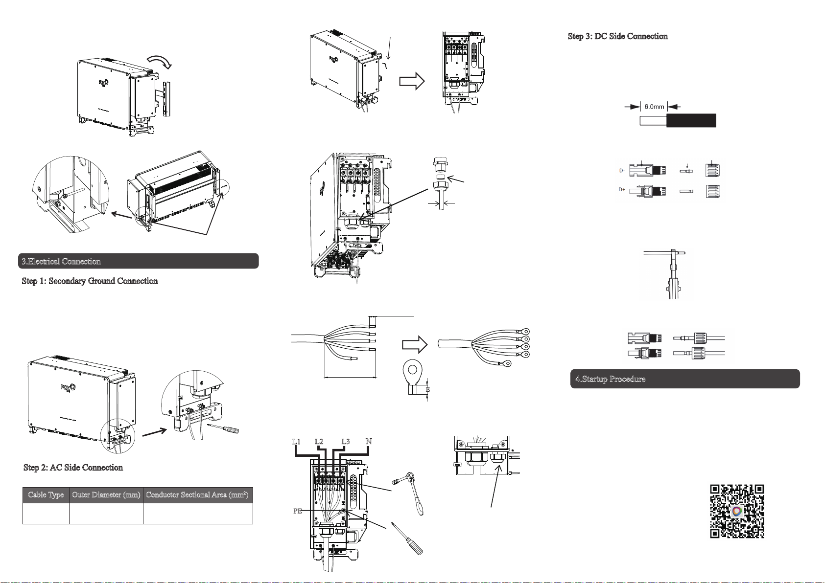
3.Electrical Connection
4 5 6
·
4.Startup Procedure
-After checking all connections are proper, turn on the external
DC/AC breakers.
-
Turn the DC switch to “ON”.
-
The inverter will start automatically when PV panels generate
enough energy, and the LED will turn blue.
After-sales Service Mail: [email protected]
Cable Type
AC Cable 38~56 L1,L2,L3,(N) cables: 70~240
PE: 0.5~10
Outer Diameter (mm) Conductor Sectional Area (mm2)
2.Install the inverter on the hanging plate, and ensure that lugs of
the inverter are properly matched with slots of the hanging plate.
3.Secure the inverter with bolts.
1.Open the AC side wiring box with a 5mm internal hexagon
wrench. Open the breaker and prevent its accidental reclose.
1.Turn off the DC swtich.
2.It is recommended that the DC cable dedicated to photovoltaics
(2.5~4 mm²) be used to connect the PV module.
3.Trim about 6mm of insulation from the cable end.
Recommended Specification:
I
2 PCS of M6*50 bolts
Step 1: Secondary Ground Connection
Step 2: AC Side Connection
Step 3: DC Side Connection
Lock crimped ground cables to ground holes with screw locks on
the inverter case, and paint the ground screws and ground terminals
to improve anti-corrosion characteristics.
The conductor sectional area of each ground cable is 0.5~10 mm2
(4~6 mm2 is recommended).
I
2.Unscrew the lock nut of the waterproof connector and take out
multilayer sealing rings. Select the sealing ring based on the cable
outer diameter. Route the cable through the lock nut and sealing ring.
3.Peel off the protective layer and insulation layer of a certain
length and crimp the cold-pressed terminals as shown below:
Internal hexagon wrench
D
Remove this sealing
ring when the diameter
D≥47mm.
4.Secure cables to the corresponding terminals with a hexagon
socket wrench and cross screwdriver, and tighten the waterproof
cable heads.
Scan the QR for
User Manual
4.Searate the DC connector as below.
5.Insert multiple cables connected to the PV module into the pin
plug and ensure all strands are captured in the pin plug.
6.Crimp the pin plug wtih a crimping plier.
7.Route the crimped cable through the nut into the plug. When you
hear a “click”, the pin plug is properly clamped in the plug.
Plug Pin plug Contact cable nut
If the PE cable is connected
separately, route the cable
through the spare waterproof
cable head.
PE
L1 L2 L3
N
L1
L2
L3
N
L=E+2~3mm
≤270mm
E
L1
L2
L3
N
PE PE
V1.0

Other manuals for R Series

1

Other FoxESS Inverter manuals

FoxESS LV5200 User manual

FoxESS

FoxESS LV5200 User manual

FoxESS S Series User manual

FoxESS

FoxESS S Series User manual

FoxESS T Series User manual

FoxESS

FoxESS T Series User manual

FoxESS S700-G2 User manual

FoxESS

FoxESS S700-G2 User manual

FoxESS E Series User manual

FoxESS

FoxESS E Series User manual

FoxESS KH Series User manual

FoxESS

FoxESS KH Series User manual

FoxESS H1 Series User manual

FoxESS

FoxESS H1 Series User manual

FoxESS F-G2 Series User manual

FoxESS

FoxESS F-G2 Series User manual

FoxESS H3 Series User manual

FoxESS

FoxESS H3 Series User manual

FoxESS US Series User manual

FoxESS

FoxESS US Series User manual

FoxESS T Series User manual

FoxESS

FoxESS T Series User manual

FoxESS R Series User manual

FoxESS

FoxESS R Series User manual

Popular Inverter manuals by other brands

Lenze L-force 8400 Series Mounting instructions

Lenze

Lenze L-force 8400 Series Mounting instructions

Champion Global Power Equipment 200955 Operator's manual

Champion Global Power Equipment

Champion Global Power Equipment 200955 Operator's manual

Envertech EVT1600SE user manual

Envertech

Envertech EVT1600SE user manual

SMA Solar Technology SUNNY BOY 3.0 operating manual

SMA Solar Technology

SMA Solar Technology SUNNY BOY 3.0 operating manual

Radio Shack 22-146 owner's manual

Radio Shack

Radio Shack 22-146 owner's manual

AMV ELECTRONICA SK3000 Series user manual

AMV ELECTRONICA

AMV ELECTRONICA SK3000 Series user manual

Voltronic Power Axpert MEX-1500 Service manual

Voltronic Power

Voltronic Power Axpert MEX-1500 Service manual

Chyron infinit! series Operation manual

Chyron

Chyron infinit! series Operation manual

Mitsubishi Electric 800 Series manual

Mitsubishi Electric

Mitsubishi Electric 800 Series manual

Jntech JNP370LS-V1 Quick installation

Jntech

Jntech JNP370LS-V1 Quick installation

Humless 1500 Series instructions

Humless

Humless 1500 Series instructions

Shinefar SF-1k-TL user manual

Shinefar

Shinefar SF-1k-TL user manual

Batterytech E-Gen 400 user manual

Batterytech

Batterytech E-Gen 400 user manual

INFOSEC C3 MPPT user guide

INFOSEC

INFOSEC C3 MPPT user guide

MARSS Solar Defender ALM-6814 Installation and programming manual

MARSS

MARSS Solar Defender ALM-6814 Installation and programming manual

MEIDEN THYFREC-VT240S instruction manual

MEIDEN

MEIDEN THYFREC-VT240S instruction manual

Deye SUN-3.6K-G user manual

Deye

Deye SUN-3.6K-G user manual

SunSynk SUNSYNK-3K-SG04LP1 Installer manual

SunSynk

SunSynk SUNSYNK-3K-SG04LP1 Installer manual

manuals.online logo
manuals.online logoBrands
  • About & Mission
  • Contact us
  • Privacy Policy
  • Terms and Conditions

Copyright 2025 Manuals.Online. All Rights Reserved.