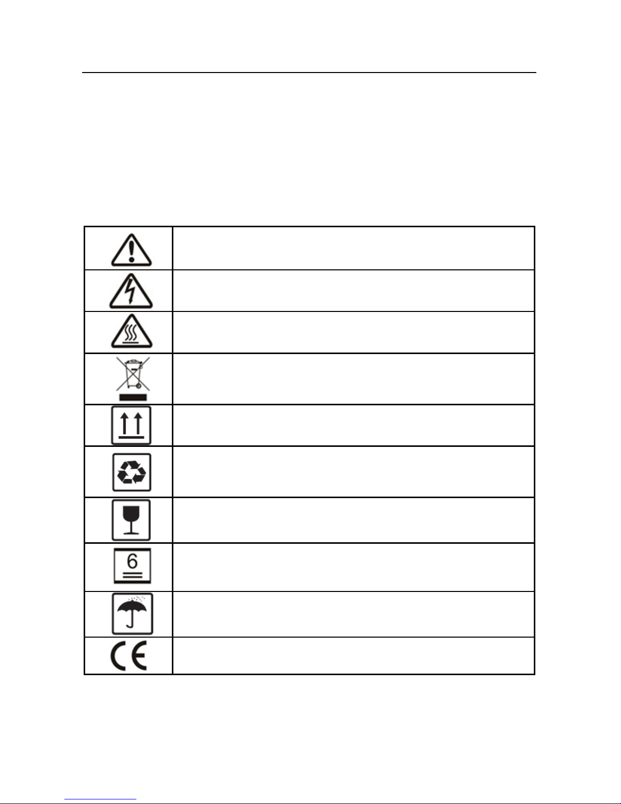
Zeus Appollo Z21 Series User manual

Zeus Appollo Z21 Series Hybrid Inverter -
Installation Manual

1
Table of Contents
1. Introduction .................................................................................................... 2
2. Important Safety Warning .............................................................................. 2
2.1 Symbols ................................................................................................ 3
2.2 Safety .................................................................................................... 4
3. Installation ..................................................................................................... 5
3.1 Packing List .......................................................................................... 5
3.2 Product Overview ................................................................................. 6
3.3 Selecting The Mounting Location ......................................................... 6
3.4 Mounting .............................................................................................. 8
4. Electrical Connection ...................................................................................... 9
4.1 AC Output Connection ......................................................................... 9
4.2 PV Connection .................................................................................... 11
4.3 Battery Connection ............................................................................. 13
4.4 RS485 Connection .............................................................................. 15
4.5 EzMeter Connection ........................................................................... 16
4.6 EzConverter Connection (optional) .................................................... 17
4.7 WiFi Connection ................................................................................ 20
4.8 WiFi Reset & Reload ......................................................................... 20
4.9 USB Connection ................................................................................. 21
5. LED Lights Illustration.................................................................................. 21
6. Z21Manage Operation Illustration ................................................................. 22
6.1 Download and Install .......................................................................... 22
6.2 Setting ................................................................................................. 22
6.3 Current Data Display .......................................................................... 25
6.4 Historical Data Display ....................................................................... 27
7. Working Modes ............................................................................................ 28
8. Error Messages.............................................................................................. 31
9. Specifications ................................................................................................ 32
11. Certificates .................................................................................................. 34

2
1. Introduction
Zeus Appollo Solar Z21 series hybrid inverters are bidirectional which enables
the PV system to direct excess power to a battery storage facility.
Energy produced by the PV system is designed to optimize consumption; excess
energy is used to charge the batteries, and when fully charged power is then fed
into the public grid.
When PV energy output is insufficient to support the connected loads, the system
automatically draws power from the batteries if they are charged and available. If
the battery capacity is insufficient to meet consumption requirements, power will
be automatically sourced from the public grid.
Zeus Appollo Solar Z21 series inverter is designed for both indoor and outdoor
use.
Figure 1-1 Basic hybrid PV system overview
2. Important Safety Warning
Before operation, please read all instructions and warnings on the unit and in this
manual. Please keep the manual where it can be accessed easily.
The Z21 series inverter
marketed by the
Beijing Hua Xin Liu He Investment

3
(Australia) Pty Ltd. (hereinafter referred to as Zeus Appollo Solar) strictly
conforms to all related safety requirements during design and testing phases.
Safety regulations relevant to the installation location shall be followed during
installation, operation and maintenance.
Improper operation may result in a risk of electric shock or damage to the
equipment and/or property.
2.1 Symbols
Caution! - Failure to observe a warning indicated in this
manual may result in injury.
Danger of high voltage and electric shock!
Danger of hot surface!
Product should not be disposed as household waste.
This side up; the package must always be transported, handled
and stored in such a way that the arrows always point upwards.
Components of the product can be recycled.
Fragile; the package/product should be handled carefully and
never be tipped over or slung.
No more than 6 identical packages may be stacked on each
other.
Keep dry; the package/product must be protected from
excessive humidity and must be stored under cover.
CE Mark

4
Residual voltage exists in the inverter; before commencing any
maintenance, at least 5 minutes must be allowed for the
capacitor in the inverter to fully discharge.
2.2 Safety
Installation, maintenance and connection of inverters must be performed by
qualified personnel, in compliance with local electrical standards,
regulations and the requirements of local power authorities and/or
companies.
To avoid electric shock, DC input and AC output of the inverter must be
terminated at least 5 minutes before performing any installation or
maintenance.
The temperature of some parts of the inverter may exceed 60
℃
during
operation. To avoid being burnt, do not touch the inverter during operation.
Let it cool before touching it.
Ensure children are kept away from inverters.
Do not open the front cover of the inverter. Apart from performing work at
the wiring terminal (as instructed in this manual), touching or changing
components without authorization may cause injury to people, damage to
inverters and may void the warranty.
Static electricity may damage electronic components. Appropriate
procedures must be adopted to prevent such damage to the inverter;
otherwise the inverter may be damaged and the warranty will be voided.
Ensure the output voltage of the proposed PV array is lower than the
maximum rated input voltage of the inverter; otherwise the inverter may be
damaged and the warranty will be voided.
PV modules should have an IEC61730 class A rating. If the maximum AC
mains operating voltage is higher than the PV array maximum system
voltage, PV modules should have a maximum system voltage rating based
upon the AC mains voltage.
If the equipment is used in a manner not specified by the manufacturer, the
protection provided by the equipment may be impaired.
To completely isolate the inverter: switch off the DC switch, disconnect the
PV terminal, disconnect the battery terminal, and disconnect the AC
terminal.

5
USB data cable x1battery terminal x2
AC terminal x6battery cover x1
AC cover x1
negative PV plug x2positive PV plug x2
wall-mounted bracket x1inverter x1
or or
antenna x1
EzConverter(optional) x1
EzMeter x1
Completely isolate the inverter before maintenance. Do not service other
areas of the inverter when undertaking maintenance!
Do NOT insert or extract the AC and DC terminals when the inverter is in
operation.
Electrical installation & maintenance shall be conducted by a licensed
electrician.
All equipment shipped to Australia shall comply with Australia National
Wiring Rules.
3. Installation
3.1 Packing List
Before installation, please inspect the unit. Be sure that nothing inside the
package is damaged. You should have received the following items inside of the
package:

6
user manual
user manual x1
flat head screw x5
pan head screw x8
warranty
Card
warranty card x1
WiFi fast
installation
fast installation x1 WiFi fast installation x1
fast
installation
expansion bolt x6 hexagon head screw x2
3.2 Product Overview
Figure 3.2-1
1. Battery input ports
2. PV input ports
3. DC switch (optional)
4. Wireless port
5. USB port
6. RS485 ports
7. AC output ports
1 2 3 4 6 7
5
3.3 Selecting The Mounting Location
Mounting location should be selected based on the following recommendations:
The installation method and mounting location must be suitable for the
inverter's weight and dimensions.
Mount on a solid surface.

7
Select a well-ventilated location sheltered from direct sunlight.
Install vertically or tilted backward by a maximum of 15°. The device must
not be installed with a sideways tilt. The connection area must point
downwards. Refer to Figure 3.3-1.
Figure 3.3-1
15¡ ã
In order to achieve optimal performance, the ambient temperature should
be less than 45 °C.
For the accessibility of monitoring the LED lights and possible
maintenance activities, please install the inverter at eye level.
Inverters should NOT be installed near flammable and explosive items.
Any strong electro-magnetic equipment should be kept away from the
installation site.
The product label and the warning symbol must be visible after installation.
Please avoid direct sunlight, rain exposure, or snow accumulation when
locating the installation point.
direct sunlight rain exposure snow lay up
Figure 3.3-2
no direct sunlight
no rain exposure no snow lay up
C:\Documents and Settings\yjl\桌面\防晒_ACD_2.png
C:\Documents and Settings\yjl\桌面\防晒_ACD_3.png

8
To facilitate heat dissipation and convenient dismantling, the minimum
clearances around the inverter should be no less than the following:
upward 300mm
downward 500mm
front 300mm
both sides 500mm
Figure 3.3-3
500mm 500mm
300mm
300mm
500mm
3.4 Mounting
Remember that this inverter is heavy! Please be careful when removing from the
packaging.
1. Use the wall-mounted bracket as a template and drill 6 holes on
the wall, 10 mm in diameter and 80 mm in depth. Refer to Figure
3.4-1.
2. Fix the wall mounting bracket on the wall with the six expansion
bolts provided in the accessory bag.
3. Carry the inverter by holding the two sides of the heat sink. Refer
to Figure 3.4-2.
4. Place the inverter on the wall-mounted bracket. Refer to Figure
3.4-3, Figure 3.4-4.

9
457mm
229mm
117mm
105mm
400mm
Figure 3.4-1 Figure 3.4-2
Figure 3.4-3 Figure 3.4-4
a
b
detail a
detail b
4. Electrical Connection
4.1 AC Output Connection
Before connecting to the grid and the load, please install a separate AC breaker
(
250VAC/30A
)
between the inverter and the grid. This will ensure that the
inverter can be securely disconnected during maintenance.
It's very important for system safety and efficient operation to use the appropriate
cable for the AC connection. To reduce the risk of injury, please use the suitable
recommended cable size. Refer to Figure 4.1-1.

10
Description Size
A External diameter of the wire 10mm-12mm
B Sectional area of conducting materials 3mm -4mm
C Length of bare wire Approx.10mm
2 2
Figure 4.1-1
AB
C
Please adhere to the following steps when making an AC connection:
1. Check the grid voltage and frequency at the connection point of
the inverter. It should meet the Zeus Appollo Solar products’
specification.
2. Measure the impedance between neutral cable and earth cable
,
make sure it does not exceed 10 ohms.
3. Disconnect the AC breaker between the inverter and the grid.
4. Disconnect the screw cap from the insulator.
5. Disconnect the waterproof ring from the insulator.
6. Feed the cable through the components in this order: screw cap,
waterproof ring, insulator, AC cover and AC terminal. Refer to
Figure 4.1-2.
7. Compress the terminal head using an appropriate tool and screw
down the screw cap slightly. Refer to Figure 4.1-3
、
Figure 4.1-4.
8. Insert the AC terminals into the corresponding holes and fasten
them with a screwdriver, then fasten the AC cover with pan head
screws provided in the accessory bag. Refer to Figure 4.1-5
、
Figure 4.1-6
、
Figure 4.1-7.
9. Screw down the screw cap again.
cable
Figure 4.1-2 Figure 4.1-3
waterproof ring AC cover AC terminal
screw cap insulator
crimp

11
Figure 4.1-4 Figure 4.1-5
cable core section after crimp
Figure 4.1-6 Figure 4.1-7
L----line N----neutral PE----earth
back-up
terminal grid terminal
pan head screw
4.2 PV Connection
Before connecting the PV panels, ensure the plug connectors have the correct
polarity. Incorrect polarity could permanently damage the inverter.
Check the short-circuit current of the PV string. The total short-circuit current
must not exceed the inverter’s maximum PV current.
The PV array should not be connected to the grounding conductor.
Please use the PV plugs provided in the accessory bag.
The system designer or installer must ensure that the minimum array
insulation resistance to the ground, when selecting the PV panel and

12
designing the system, is based on the minimum value of the design of the PV
functional grounding in the inverter. The minimum system value of a total
resistance of 19.33kΩmust be attained. There is a risk of electrical shock if
the total minimum resistance requirement is not met.
There are two types of PV plugs----SUNCLIX series and MC4 series. Refer
to Figure 4.2-1.
Figure 4.2-1
SUNCLIX series MC4 series
The installation method of SUNCLIX series Refer to Figure 4.2-2.
inverter side
Figure 4.2-2
7mm
7mm
2.5~4mm
2.5~4mm
2
2
The installation method of MC4 series Refer to Figure 4.2-3.

13
inverter side
compress by
professional tool
2.5~4mm
2
2.5~4mm
2
7mm
7mm
Figure 4.2-3
4.3 Battery Connection
Before connecting to a battery, please install a separate DC breaker (60A for
Z21I3K6D48 and 120A for Z21I4K6D48) between the inverter and the battery.
This will ensure that the inverter can be securely disconnected during
maintenance.
Be aware of electric shock and chemical hazards!
It is a normal phenomenon that an electric arc occurs when connecting a
battery to the inverter without the use of a DC breaker.
It's very important for system safety and efficient operation to use an
appropriate cable for the battery connection. To reduce the risk of injury,
please use the correct recommended cable size. Refer to Figure 4.3-1.
Description Size
A External diameter of the wire 10mm-12mm
B Sectional area of conducting materials 20mm -25mm
C Length of bare wire Approx.10mm
2 2
Figure 4.3-1
AB
C
Suggestion: If the battery is to be installed internally, please refer to the

14
battery manufacture’s user manual.
Suggestion: The battery should be installed with the correct distance between
each battery unit, for details please refer to the battery manufacture’s user
manual.
The number of battery cells used will be determined by the customer
depending on the required capacity, however the choice will be limited to a
total series voltage array of 48 V.
Please follow the steps below to implement battery connection:
1. Check the nominal voltage of batteries. The nominal input voltage
should meet Zeus Appollo product specification.
2. Disconnect the DC breaker between the inverter and the battery.
3. Disconnect the screw cap from the insulator.
4. Disconnect the waterproof ring from the insulator.
5. Feed the cable through the components in this order: screw cap,
waterproof ring, insulator, battery cover and battery terminal.
Refer to Figure 4.3-2.
6. Compress the terminal head using an appropriate tool and screw
down the screw cap slightly. Refer to Figure 4.3-3, Figure 4.3-4.
7. Insert the battery terminals into the corresponding apertures and
fasten them with a screwdriver and a spanner, then fasten the
battery cover with the pan head screws provided in the accessory
bag. Refer to Figure 4.3-5, Figure 4.3-6, Figure 4.3-7.
8. Screw down screw cap again.
cable
Figure 4.3-2 Figure 4.3-3
waterproof ring
battery cover
battery terminal
screw cap
insulator
crimp

15
Figure 4.3-4 Figure 4.3-5
cable core section after crimp
+
----red cable
-
----black cable
positive
terminal
negative
terminal
Figure 4.3-6 Figure 4.3-7
hexagon head screw pan head screw
4.4 RS485 Connection
The RS485 interfaces are used for EzConverter and EzMeter communication. The
cable length should not exceed 800m. For the connection procedures for the
RS485 please refer to chapter 4.5, chapter 4.6.
Please follow the steps below to implement the RS485 connection on the inverter
side:
1. Remove the RS485 waterproof assembly from the inverter.
2. Disconnect the screw cap from the insulator.
3. Disconnect the waterproof ring from the insulator.
4. Feed the cable through the components in this order: screw cap,
waterproof ring, insulator, RS485 cover. Refer to Figure 4.4-1.
5. Insert the cable wire into the corresponding slots in the crystal
head and compress using an appropriate tool, then screw down the
cap slightly, refer to Figure 4.4-1.

16
6. Put the crystal head insert into the corresponding inner slots of the
inverter.
7. Fasten the RS485 waterproof assembly to the inverter.
8. Screw down the screw cap again.
cable waterproof ring RS485 cover crystal head
screw cap insulator
Figure 4.4-1
PIN
1
2
3
4
5
6
7
8
RESERVED
RX_RS485B
RX_RS485A
TX_RS485B
TX_RS485A
FunctionColor
orange/white
orange
green/white
blue
blue/white
green
brown/white
brown
RS485 waterproof assembly
RESERVED
RESERVED
RESERVED
4.5 EzMeter Connection
The EzMeter may detect the current magnitude and direction, to control the
working condition of the inverter. The communication between the inverter and
EzMeter is via an RS485. The cable length should not exceed 800m.
For the connection method of a single phase EzMeter, please refer to Figure
4.5-1.

17
Load
PIN
1
2
3
4
5
6
7
8
RESERVED
RX_RS485B
RX_RS485A
TX_RS485B
TX_RS485A
FunctionColor
orange/white
orange
green/white
blue
blue/white
green
brown/white
brown
RESERVED
RESERVED
RESERVED
Breaker
Connection illustration of single phase system
T568B
Grid
RESERVED
FunctionColor
orange/white
orange
green/white
blue
blue/white
green
brown/white
brown
RESERVED
RESERVED
RESERVED
Figure 4.5-1
EzMeter
if constant blink, connection ok.
Breaker
The connection method of a three phase EzMeter, refer to Figure 4.5-2.
Load
PIN
1
2
3
4
5
6
7
8
RESERVED
RX_RS485B
RX_RS485A
TX_RS485B
TX_RS485A
FunctionColor
orange/white
orange
green/white
blue
blue/white
green
brown/white
brown
RESERVED
RESERVED
RESERVED
Connection illustration of three phase system(optional)
T568B
Figure 4.5-2
RESERVED
FunctionColor
orange/white
orange
green/white
blue
blue/white
green
brown/white
brown
RESERVED
RESERVED
RESERVED
EzMeter
Breaker
Grid
if constant blink, connection ok.
Breaker
4.6 EzConverter Connection (optional)
It will be required to configure the EzConverter if a lithium battery is used in the
system, to enable communication with the battery BMS.
If the light is flashing, the connection is
ok
If the light is flashing, the
connection is ok

18
Communication between the inverter and the EzConverter is via an RS485.
Communication between the lithium battery and the EzConverter can be via an
RS485 or CAN or an RS232 (depending on the Li-Ion battery communication
type). The cable length should not exceed 2m.
Choose a corresponding switch circuit for the lithium battery, according to the
switch protocol comparison table of the lithium battery in the user manual.
1. Lithium battery communication connects to an EzConverter via RS485
interface if the protocol is RS485. Refer to Figure 4.6-1.
2. Lithium battery communication connects to an EzConverter via CAN
interface if the protocol is CAN. Refer to Figure 4.6-2.
3. Lithium battery communication connects to an EzConverter via RS232
interface if the protocol is RS232. Refer to Figure 4.6-3.
RS485
Figure 4.6-1
Battery
Li-Ion
PIN
1
2
3
4
5
6
7
8
RESERVED
RX_RS485B
RX_RS485A
TX_RS485B
TX_RS485A
FunctionColor
orange/white
orange
green/white
blue
blue/white
green
brown/white
brown
RESERVED
RESERVED
RESERVED
T568B

19
CAN
Figure 4.6-2
Battery
Li-Ion
PIN
1
2
3
4
5
6
7
8
RESERVED
RX_RS485B
RX_RS485A
TX_RS485B
TX_RS485A
FunctionColor
orange/white
orange
green/white
blue
blue/white
green
brown/white
brown
RESERVED
RESERVED
RESERVED
T568B
RS232
Figure 4.6-3
Battery
Li-Ion
PIN
1
2
3
4
5
6
7
8
RESERVED
RX_RS485B
RX_RS485A
TX_RS485B
TX_RS485A
FunctionColor
orange/white
orange
green/white
blue
blue/white
green
brown/white
brown
RESERVED
RESERVED
RESERVED
T568B
Working status of the EzConverter as below table 4.6-1.
TABLE4.6-1
Silk-Screen LED Colour EzCoverter Status Note LED Display Status
Other manuals for Z21 Series
1
Table of contents
Other Zeus Appollo Inverter manuals

Zeus Appollo
Zeus Appollo Z20I1K User manual

Zeus Appollo
Zeus Appollo Z10I13KDT User manual

Zeus Appollo
Zeus Appollo Z21 Series User manual

Zeus Appollo
Zeus Appollo Single Phase Series User manual

Zeus Appollo
Zeus Appollo Z20I4KT User manual

Zeus Appollo
Zeus Appollo Z10I1K User manual

Zeus Appollo
Zeus Appollo Z10I3KD User manual
Popular Inverter manuals by other brands

Veichi
Veichi AC100-T3-1R5G manual

Mitsubishi Electric
Mitsubishi Electric FR-D700 Series manual

AIMS
AIMS AIMS Power PE300012230S user manual

WELDING INDUSTRIES
WELDING INDUSTRIES 125i MC91-0 Operator's manual

ResMed
ResMed Flow Generator VPAP Adapt SV user guide

Lenze
Lenze L-force HighLine C 8400 Series Reference manual