Oliver LEGACY ELITE 2022 User manual

VIEW THIS MANUAL ONLINE AT OLIVERTRAVELTRAILERS.COM
LEGACY ELITE & LEGACY ELITE II
OPTIONAL
FEATURES
COMPONENT MANUALS


OPTIONAL COMPONENT WARRANTY INFORMATION INDEX
ANDERSEN HITCH
AUTO-DRAIN
CONVECTION MICROWAVE
CRADLEPOINT WIRELESS WAN
HYPERVENT CONDENSATION PREVENTION MATTING
KEYLESS ENTRY DOOR LOCK
NATURE’S HEAD COMPOSTING TOILET
LAGUN TABLE
LITHIONICS LITHIUM BATTERIES
LIFELINE AGM BATTERIES
TRUMA AQUAGO COMFORT WATER HEATER
TRUMA ELECTRIC ANTIFREEZE KIT
FURRION REAR/BACKUP CAMERA
SURECALL FUSIONGO . CELL BOOSTER
OMNI DIRECTIONAL ANTENNAS
WINEGARD CARRYOUT G+ SATELLITE ANTENNA
XANTREX FREEDOM XC PRO INVERTER
XANTREX INVERTER REMOTE
ZAMP CHARGE CONTROLLER
OPTIONAL FEATURES COMPONENT MANUALS
TABLE OF CONTENTS
4-6
7-21
22
23-37
38-147
148
149
150-173
174
175-196
197-236
237-280
281-292
293-315
316-327
328-333
334-341
342-397
398-399
400-407

4
Anderson “No-Sway” Weight Distribution Hitch
Andersen Hitches
3125 North Yellowstone Highway, Idaho Falls, ID 83401-1709
Email: N/A
Phone: 800-635-6106
Warranty: Limited Lifetime
Barker’s Auto Drain
Barker Manufacturing
1125 Watkins Road, Battle Creek, MI 49015
Email: sales@barkermfg.com
Phone: (888) 367-6978
Warranty: 2-Year Extended
Bright Way Group Batteries
Contact Oliver Travel Trailers Service Department for Warranty
Warranty: 1-Year
Cradlepoint Wireless WAN
Cradlepoint
1111 W Jefferson Street, Boise, ID 83702
Phone: 855-813-3385
Warranty: 1-Year Limited
Furrion Backup Camera
Furrion
52567 Independence Ct., Elhart, IN 46514
Email: [email protected]
Phone: 888-354-5792
Warranty: 1-Year Limited
High Pointe Convection Microwave
Contact Oliver Travel Trailers Service Department for Warranty
Warranty: 1-Year
OPTIONAL COMPONENT WARRANTY INFORMATION

5
HyperVent Condensation Prevention Matting
HyperVent Marine
1301 4th St., Marysville, WA 98270
Email: hypervent_info@comcast.net
Phone: 360-651-1365
No Warranty
Lithionics Lithium Batteries
Lithionics Battery
Email: [email protected]
Phone: 727-726-4204
Warranty: 5-Years
Lifeline Deep Cycle Batteries – Legacy Elite
Lifeline Batteries Inc.
292 E Arrow Highway, San Dimas, CA 91773
Email: N/A
Phone: 909-599-7816
Warranty: 5-Years
Magnedyne Omni-Directional Antenna
Magnadyne Corporation
1111 W. Victoria Street, Compton, CA 90220
Email: [email protected]
Phone: 1-310-735-2000
Warranty: 1-Year
Nature’s Head Composting Toilet
Nature’s Head, Inc.
PO Box 250, Van Buren, Ohio 45889
Email: [email protected]
Phone: 251-295-3043
Warranty: 5-Year
SureCall Fusion2Go 3.0 Cell Phone Amplifier
SureCall
48346 Milmont Drive, Fremont, CA 94538
Email:[email protected]om
Phone: 1-888-365-6283
Warranty: 3-Year
OPTIONAL COMPONENT WARRANTY INFORMATION

6
OPTIONAL COMPONENT WARRANTY INFORMATION
TRUMA AquaGo Comfort Tankless Water Heater
Truma Corp.
825 E Jackson Blvd, Elkhart, IN 46516
Email: info@trumacorp.com
Phone: 1-855-55-TRUMA
Warranty: 1-Year
(2-Year when registered at time of purchase)
Wifi Ranger WIFI Booster
Mito Corporation
213 County Road 17, Elkhart, IN 46516
Email: questions@wifiranger.com
Phone: (574) 295-2441
Warranty: 1-Year
Winegard Carryout G2 Satellite
Winegard Company
3000 Kirkwood Street, Burlington, IA 52601
Email: [email protected]
Phone: 1-800-788-4417
Warranty: 2-Years Parts, 1-Year Labor
Xantrex Inverters & Remote
Xantrex
541 Roske Drive, Suite A, Elkhart, IN 46516
Email: N/A
Phone: 800-670-0707
Warranty: 24 Months
ZAMP Solar Package
ZAMP Solar, LLC.
63255 Jamison Rd, Bend, Oregon 97703
Email: [email protected]
Phone: 541-728-0924
Warranty: 1-Year Limited

7
IMPORTANT! DEALER OR INSTALLER: Please make sure your customer receives
this manual for safety tips, warranty, and future removal or installation information
Andersen “No-Sway” Weight Distribution Hitch
INSTALLATION MANUAL
For all 4″ Drop/Rise WD Kits AND all 8″ Drop/Rise WD Kits
Featuring the patented, super-quiet Anti-Sway and Anti-Bounce TMD (True Motion-Dampening™) system
3″, 2-1/2″ & 2″ Shanks Available
16,000 lbs GTWR (2-5/16” 16K ball) • 14,000 lbs GTWR (2-5/16″ ball) • 10,000 lbs GTWR (2″ ball) • 1,400 lbs tongue
Page 2 & 3
Page 4
Page 5
Page 5
Page 6
Page 7
Page 11
Page 11
Page 12
Page 12
Page 13
Page 14
Page 15
Important Information and Warnings ..................................
Parts Illustration .................................................................
Section 1: Preparation .......................................................
Section 2: Installing Rack & Ball Housing ..........................
Section 3: Attaching Tension Plate and Chains .................
Section 4: Attaching Frame Brackets to Trailer ..................
Section 5: Setting the Tension ...........................................
Section 6: Checking and Adjusting the Tension .................
Troubleshooting .................................................................
Unhooking the Trailer from the Tow Vehicle .......................
Hooking the Tow Vehicle back up to the Trailer .................
Popular Add-ons for your Ultimate Connection ..................
Warranty Information .........................................................
Table of Contents
andersenhitches.com
IMPORTANT ALERT: Potential issues may exist when using the Andersen ‘No Sway’ Weight Distribution
Hitch with Atwood 88007, 88010, 88555 and 88600 couplers. (For more information, see page 2)
NOTE: THERE IS NEVER A NEED TO GREASE BALL OR COUPLER
Want to see a video of the install?
Use your Smart Phone to scan the
QR Code above or go to
our Installation videos on the web at
help.AndersenHitches.com/install
ANDERSEN HITCH

8
Page 2 of 16 • Andersen Weight Distribution Hitch Installation Manual 5-2021 • www.AndersenHitches.com
IMPORTANT ALERT!
Potential issues may exist when using the Andersen ‘No Sway’ Weight
Distribution Hitch with Atwood 88007, 88010, 88555 and 88600 couplers.
All other Atwood couplers work great.
When these few Atwood couplers are combined with the Andersen Weight Distribution system — and other
weight distribution systems — there is a potential issue where some couplers can become unlatched over time
due to wear on the internal latch system. This issue is present because of the unique design of the couplers.
To our knowledge, this potential issue ONLY affects the Atwood 88007, 88010, 88555 and 88600
couplers. All other Atwood couplers work great. Older (pre-Atwood) Marvel couplers also work great.
Newer models may also encounter these issues if designed in a similar style.
Although we have heard of Atwood coupler users who have had some success with modifying the latch
mechanism and greasing the paw and ball, Andersen Manufacturing does not ofcially endorse any
solution other than replacing the coupler itself with a different Atwood coupler.
(See your local Dealer or contact us for recommendations on a replacement coupler)
Please feel free to contact us if you have further concerns or questions.
Customer Service: 208.523.6460
customerservice@anderseninc.com
help.AndersenHitches.com
Using the WD Hitch with late model
vehicles that have electronic anti-sway
The Andersen WD Hitch features its own sway controls that are designed to auto-adjust to the load in your trailer
and prevent trailer sway when installed properly. Unfortunately, some newer electronic anti-sway systems can
misread the anti-sway efforts of the Andersen WD Hitch and the anti-sway system may actually cause the trailer to
sway as the two systems work against each other.
These potential issues typically occur with electronic anti-sway systems that are designed to detect trailer sway
and automatically use the vehicle brakes to help control the sway. Please note that this type of anti-sway system is
different from electronic traction control, which does not cause this type of problem. If you experience this type of
issue, you will need to turn off the electronic anti-sway in your vehicle in order to tow with the Andersen WD Hitch.
This issue is most likely to occur in 2011 and newer truck models from Ford, GMC, Dodge, and Chevy. Refer to your
tow vehicle’s owners manual to determine if you have electronic anti-sway and how to disable it while using the WD
Hitch to tow.
ANDERSEN HITCH

9
Page 3 of 16 • Andersen Weight Distribution Hitch Installation Manual 5-2021 • www.AndersenHitches.com
A NOTE ABOUT SUSPENSION
FOR SAFETY Secure your trailer using wheel chocks before setting up or adjusting the Andersen
Weight Distribution Hitch.
The operator is responsible for making necessary adjustments to the weight distribution hitch to maximize
performance for each trip and every time the load changes.
REMEMBER Any time you change your load weight in the towing vehicle or trailer, re-check to see how
level you are and make adjustments as needed. Also, before each trip — and regularly during a trip —
check all hardware, bolts and nuts for wear and fatigue. Make sure that they are all properly tightened
and that all pins and clips are secured in place.
It is critical to check the tire pressure of each of the tires on the trailer and tow vehicle before towing.
Refer to your vehicle’s owners manual for maximum towing capacity. DO NOT overload your vehicle —
failure to follow vehicle manufacturer’s recommendations could result in damage to your vehicle, personal
injury or death. Your combined load and trailer weight should be less than the lowest weight rating
of your tires, vehicle, and hitch. You should also refer to the manufacturer’s instructions for your trailer
and follow all safety warnings, setup instructions, and maintenance before installing your hitch.
Make sure the trailer coupler is coupled and secured properly before towing, and that safety chains are in
place.
Do not modify Weight Distribution Hitch components outside of the recommendations found within this
manual. (e.g. shortening/extending chains, welding brackets to the trailer frame, etc.)
IMPORTANT! No hitch setup can guarantee that trailer sway will be avoided altogether. It is the
driver’s responsibility to adjust equipment and driving habits according to towing conditions. The driver is
responsible for their own safety and the safety of passengers and those around them.
Ensure that the suspension of both the tow vehicle and trailer are in good working order before you
embark on a trip. Bad suspension may result in the Weight Distribution Hitch not being able to properly
even out your load. Always load trailer correctly according to the manufacturer’s recommendations for
maximum weight limits and cargo placement. Do not overload trailer or towing vehicle.
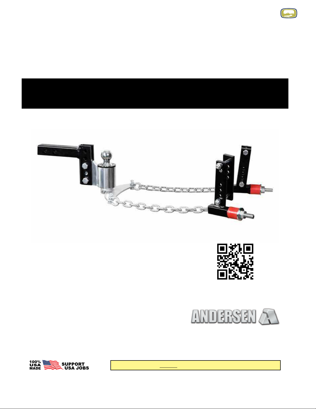
We are proud that our Weight Distribution Hitch is rated up to 1,400 lbs tongue weight to meet the SAE
J-684 strength requirements. However, if your trailer tongue weight is pushing 1,400 lbs, we recommend
possibly improving or ‘beeng up’ the suspension of both 1/2 ton and 3/4 ton vehicles.
NOTE: AS WITH ANY WEIGHT DISTRIBUTION HITCH,
DO NOT USE THE ANDERSEN WD HITCH WITH ANY KIND OF SURGE BRAKE SYSTEM
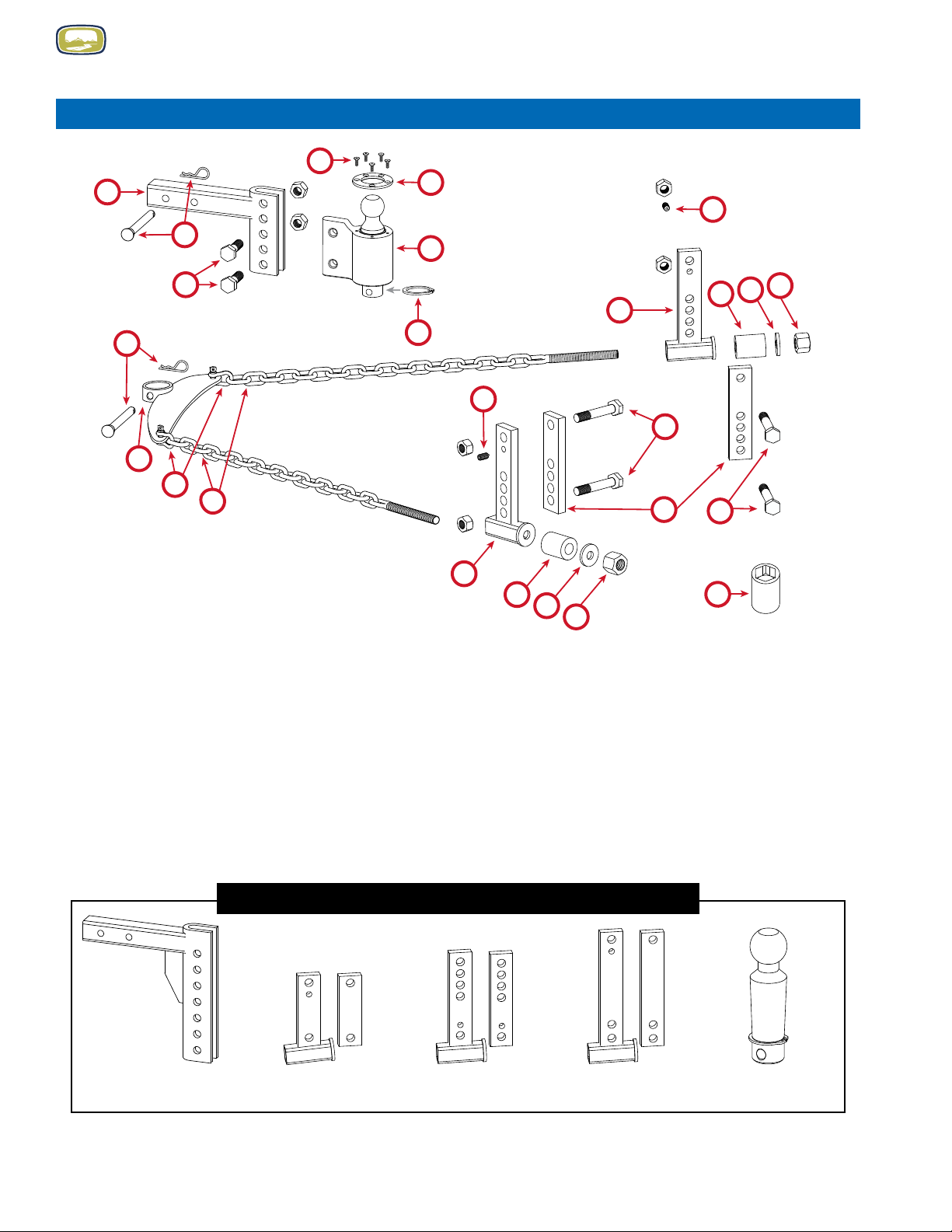
IMPORTANT INFORMATION
WARNING
ANDERSEN HITCH

10
Page 4 of 16 • Andersen Weight Distribution Hitch Installation Manual 5-2021 • www.AndersenHitches.com
TOOLS NEEDED FOR INSTALLATION
Measuring Tape
5/16″ Allen Wrench
Two 1-1/8″ Box End or Adjustable Wrenches
Two 15/16″ Box End or Adjustable Wrenches
Torque Wrench capable of 150 ft-lbs of torque
1-1/4″ Socket (provided, ts 1/2″ drive)
1. Adjustable Rack (4″ drop/rise rack with 2″ shank shown)
2. Pin and Clip for adjustable rack and ball housing (2 Sets) #3430
3. Ball Housing Adjustment Bolts and Nuts (3/4″ x 2-1/2″, 2 sets) #3378
4. Ball Housing Plate Screws (5 pcs, attached to ball housing)
5. Ball Housing Plate (attached to ball housing)
6. Ball Housing (includes housing, tapered ball, and brake material cone) #3383, #3355
7. Spring Clip (attached to tapered ball) #3376
8. Frame Bracket Bolts and Nuts (5/8″ x 4″, 4 sets)
9. ‘Pointed’ Set Screws (2 or 4 pcs, depending on your specic WD kit)
10. Outside Frame Brackets (2 pcs, universal 3″/4″/5″/6″ brackets shown)
11. Inside Frame Brackets (2 pcs, universal 3″/4″/5″/6″ brackets shown)
12. Tension (Triangle) Plate #3356
13. Chain Shackles (2 pcs) #3374
14. Tension Chains with End Bolts (2 pcs) #3357
15. High-Density Urethane Springs (2 pcs) #3358
16. Spring Washers (2 pcs) #3388
17. Tension Nuts (1-1/4″, 2 pcs) #3370
18. 1-1/4″ Socket #3384
PARTS ILLUSTRATION – WEIGHT DISTRIBUTION HITCH
Possible Add-Ons (see page 14 for more info and products)
8″ drop/rise
adjustable rack
2″ or 2-5/16″ WD Ball
with Spring Clip
7″/8″ Brackets4-3/8″ Brackets Raised 3″/4″/5″/6″
Brackets
1
8
8
10
10
11
9
12
13
14
15 16 17
3
27
2
18
9
15 16 17
6
5
4
ANDERSEN HITCH

11
Page 5 of 16 • Andersen Weight Distribution Hitch Installation Manual 5-2021 • www.AndersenHitches.com
(A) (B) (C) (D)
2-4. Raise the tongue of the trailer up high enough so that the ball mount can comfortably t under the trailer coupler.
Back your tow vehicle up so that the ball mount is directly under the trailer coupler and then set the FULL WEIGHT of the
trailer down on the ball.
The front end of your trailer should now be about 1″ to 1-1/2″ lower than the back. If the front of the trailer is MORE
than 1-1/2″ lower than the back, you might need to raise the trailer coupler off of the Ball Housing and move the Ball
Housing up a notch or two so that it is close to level (i.e. within 1-1/2″ difference).
SECTION 1: PREPARATION
SECTION 2: INSTALLING THE RACK AND BALL HOUSING (SWAY CONTROL)
1-1. Start on level ground. If you are planning on hauling ATVs or other heavy equipment, you should load the trailer and
tow vehicle with those items beforehand. Follow proper weight distribution guidelines as laid out in the manufacturer’s
recommendations for the tow vehicle and trailer. Make sure to stay within the limitations of each manufacturer’s maximum
weight recommendations.
1-2. Ensure that the trailer is parallel to the ground by comparing measurements (A) and (B) — i.e. from the ground to the
frame on both the front and back of the trailer.
IMPORTANT! When possible, make sure that any auto-leveling
system is disabled or turned OFF temporarily during installation.
2-1. Once the trailer is level, place the adjustable rack into the hitch receiver
on your towing vehicle. Secure it to the receiver using the standard pin and clip
(provided) or your own locking pin.
(Optional locking receiver pin available from Andersen - Part #3429)
2-2. Place the Ball Housing into the adjustable rack so that the top of the ball is
about 1″ to 1-1/2″ higher than the top of the trailer’s coupler (C).
2-3. Place the two ball housing adjustment bolts through the holes in the rack and
Ball Housing unit to hold it in place (you will tighten the adjustment bolt nuts in step
3-1). At this time, you will want to measure the height of your tow vehicle
bumper (D) for use in step 3-4.
DO NOT GREASE THE BALL OR COUPLER! Since the ball and coupler move together, there is no
friction that would create a need for grease, and any grease that works its way into the ball housing
can decrease the anti-sway abilities of the Andersen WD Hitch.
ANDERSEN HITCH

12
Page 6 of 16 • Andersen Weight Distribution Hitch Installation Manual 5-2021 • www.AndersenHitches.com
3-4. With your trailer coupler locked and secured to the ball, extend your jack and RAISE THE TRAILER an inch or two
above the bumper height measurement (D) taken in installation step 2-3. This ensures that the coupler is pulling up on the
ball (which will also raise the WD rack and the back of your vehicle). Leave the trailer in this raised position while you
continue with the following steps.
SECTION 3: ATTACHING THE TENSION PLATE AND CHAINS
3-1. Raise the trailer up so there is almost no weight on the ball.
Next, place the two nuts onto the ball housing adjustment bolts and
tighten to approximately 150 ft-lbs of torque using two 1-1/8″ sockets
or wrenches. This will squeeze the sides of the adjustable rack around
the Ball Housing. Then, use the coupler latch to lock the trailer coupler
onto the ball.
IMPORTANT! For this part of the installation, make sure there is ALMOST NO WEIGHT
being placed on the ball when you lock the trailer coupler in place on the ball.
3-5. Attach the chain shackles to the Tension (Triangle) Plate by
threading the shackle pin through the hole on the plate (everything
should look like the diagram on the left).
3-6. Hand-tighten both shackle pins until they are fully seated.
Tension Plate
Fig. 3-1 Fig. 3-2 Fig. 3-3Perpendicular Angled too far Perpendicular
after backing
up at an angle
3-2. Attach the Tension Plate to the bottom of the Ball Housing by
securing it in place using the pin and clip provided (see left). If you
want to, you can use our locking receiver pin (Part #3429) for this
purpose as well.
3-3. Look at a bird’s-eye-view of the Tension Plate (see below) to make
sure that the Tension Plate is close to perpendicular to the trailer frame
(g. 3-1). If not, raise the trailer jack off the ground and use the tow
vehicle to move the Trailer forward or backward at an angle until the
plate is close to perpendicular to the trailer frame (g. 3-3). NOTE: The
plate does NOT need to be perfectly perpendicular, a little off of
perpendicular is ne.
IMPORTANT: DO NOT USE A HAMMER TO TRY AND LINE THE PLATE UP.
IMPORTANT: DO NOT USE A HAMMER TO TRY AND LINE THE PLATE UP,
IT WILL DAMAGE THE PLATE
ANDERSEN HITCH

13
Page 7 of 16 • Andersen Weight Distribution Hitch Installation Manual 5-2021 • www.AndersenHitches.com
SECTION 4: ATTACHING THE FRAME BRACKETS TO THE TRAILER
4-1. With the TRAILER STILL RAISED, attach both tension chains to the outside frame brackets using the hardware
shown below.
IMPORTANT!
Washer must be installed or
the nut will split the bushing IMPORTANT!
Approx. 1 thread showing
1. Insert the chain bolt into the SQUARE opening of the outside frame bracket (DO NOT thread it through the
round “washer” side rst). Make sure the chain is not twisted.
2. Place the red high-density urethane spring onto the protruding bolt.
3. Place the washer on the bolt (Fig. 4-1).
4. Thread the Tension Nut on the bolt until approximately 1 bolt thread is protruding from the end (Fig. 4-2).
4-2. Pull the chains tight to get an idea of where the brackets will touch the frame and check for any obstructions or wiring
that might be in the way. With one thread showing at the end of the tension nut, the frame brackets will touch the frame at
approximately 28″ or 29″. See page 10 for bracket placement on ‘Y’ Style Trailer Frames.
HOW TO HANDLE OBSTRUCTIONS
If you have any OBSTRUCTIONS or xtures on the frame that get in the way of the frame brackets, there are
two options:
1. Move/adjust the obstructing object forward or backward so it is out of the way. Some items like propane
tanks and batteries can be moved or raised using off-the-shelf frames or brackets. See your local Authorized
Andersen Dealer for further help and options.
2. Accommodate for the obstructions by removing or adding links to the WD tension chains (on the shackle
end). You can SHORTEN the chain (up to approx. 5 links, leaving 10 or more links) or ADD several inches
to the chain (as many links as needed) with no adverse effect. If you do remove/add any chain links, be sure to
remove/add the same number of links from both chains. Chain extensions (Part #3366) can be ordered through your
authorized Andersen Dealer.
SHORTENING CHAINS: You can permanently remove chain links using bolt-cutters or other cutting equipment
OR you can insert a heavy-duty threaded link between the chain and shackle to effectively shorten the chains
without actually removing links — unused links will hang free. If you do not have bolt-cutters or other cutting
equipment and want to permanently remove chain links, see your local Authorized Andersen Dealer for help.
Approx. 1 thread showing
Approx. 28″ to 29″ (+/- 1″)
Center of
Brackets
Center of
Coupler
Fig. 4-1 Fig. 4-2
IMPORTANT! Since each set up can be different, only use this MEASUREMENT as an approximate position
to look for obstructions, NOT for pre-installing brackets.
ANDERSEN HITCH

14
Page 8 of 16 • Andersen Weight Distribution Hitch Installation Manual 5-2021 • www.AndersenHitches.com
Correct Bracket Positioning
The larger brackets attached to the tension
chains should be placed on the OUTSIDE of the
trailer frame. As discussed in installation step
4-3, start by loosely attaching these outside
brackets to the smaller brackets placed on the
INSIDE of the trailer frame.
Correct Bolt Installation Order
If installing 3″/4″/5″/6″ universal brackets,
4-3/8″ brackets, or 7″/8″ brackets, begin by
loosely attaching each set of inside and outside
brackets with a frame bracket bolt and nut
through the TOP bracket holes with the nut on
the inside. Then, use a second frame bolt and
nut through the rst set of bracket holes below
the lower edge of your trailer frame. Do not
install the pointed set screws until installation
step 4-6.
If installing RAISED 3″/4″/5″/6″ brackets,
begin by loosely attaching each set of inside
and outside brackets with a frame bracket bolt
and nut through the BOTTOM bracket holes
with the nut on the inside. Then, use a second
frame bolt and nut through the rst set of bracket
holes above the upper edge of your trailer frame.
Do not install the pointed set screws until
installation step 4-6.
CAUTION! Double-check around the trailer frame to see if there are any brake lines, gas lines, or
wiring that could be damaged by installation of the frame brackets. If so, nd a way to reroute them
before nal installation.
4-3. Make sure both chains are equal in length, and relatively straight (not twisted). Then, while keeping the chains tight,
LOOSELY attach (barely hand-tighten) both pairs of frame brackets to the tongue of the trailer using the positioning below.
Do not insert the set screws yet.
NOTE: If you are installing multi-size frame brackets, use the bolt
holes that are closest to your frame size
(see picture at right for sizing on universal brackets).
Top bolt-hole
Threaded set-screw hole
3-inch bolt-hole position
4-inch bolt-hole position
5-inch bolt-hole position
6-inch bolt-hole position
Place Second
Place First
ENSURING CORRECT BRACKET INSTALLATION
Place First
Place Second
CORRECT INSTALLATION ORDER FOR:
• 3″/4″/5″/6″ (Universal) Brackets
• 4-3/8″ Brackets
• 7″/8″ Brackets
CORRECT INSTALLATION ORDER FOR:
• RAISED 3″/4″/5″/6″ Brackets
ANDERSEN HITCH

15
Page 9 of 16 • Andersen Weight Distribution Hitch Installation Manual 5-2021 • www.AndersenHitches.com
4-4. Once you have your brackets loosely connected, pull the top of the bracket sets away from the coupler until the top
and bottom bolts rest on the frame and the chains are tight — the brackets will now be angled as seen below. Now
tighten down all four bracket bolts using two 15/16″ sockets or wrenches.
4-5. Make sure all brackets are clamped tightly — we recommend around 75-90 ft-lbs of torque depending on your frame.
4-6. Using a 5/16″ allen ratchet or allen wrench, screw in all set screws until they
barely touch the trailer frame. Then, proceed to tighten them 1-1/2 to 2 more
full rotations. If you nd that your brackets tend to shift, you can use one of the
following optional set screw installation methods for a more secure connection.
NOTE: If you are installing a kit with Raised 3″/4″/5″/6″ brackets, you will use four
set screws — one set on the outside brackets and one set on the inside brackets
as shown on page 8.
1. OPTIONAL SET SCREW INSTALLATION - PRE-DRILLING
(for both Regular and C-Channel frames)
A good option to strengthen and secure the hold of the set screws is to pre-drill a 7/16″ hole into the frame where the
set screws will be located. Before drilling, insert the set screw into the frame bracket and turn it until the tip makes
contact with the frame, then turn it a little more to apply pressure and make a mark on the trailer frame. Remove the
set screw and drill a hole in the frame at the point you marked. After drilling, replace and tighten the set screws into
the hole to prevent the bracket from slipping.
C-CHANNEL FRAMES
If your trailer has a ‘C-channel’ style frame as shown in the
illustration on the right, you will need to install the set screws or
brackets using one of the two optional methods that follow. Both
optional methods are designed to help ensure a secure hold for
the brackets of your WD kit.
IMPORTANT: Some lighter frames may begin to crush if torqued too high,
so be aware of your frame’s capabilities.
NOTE: Brackets should end up at an angle on your trailer frame
ANDERSEN HITCH

16
Page 10 of 16 • Andersen Weight Distribution Hitch Installation Manual 5-2021 • www.AndersenHitches.com
2. OPTIONAL FRAME BRACKET INSTALLATION - WELDING
(for both Regular and C-Channel frames)
Using the services of a certied welder, another option is
to add a 2″ weld along the lower back side of both outside
frame brackets (on the same side the red spring is on). This
will give you a very secure installation of the frame brackets
without the need for set screws. Before welding you will need
to grind the paint off of the area to be welded.
For best performance, you will want to weld the brackets at
an angle that allows the straightest travel of the chain through
the outside bracket.
NOTE: You do not need to weld the inside frame brackets.
Should you decide to sell your trailer later, the weld could be
easily removed by prying the bracket away and grinding off
the leftover weld.
The Andersen ‘No-Sway’ Weight Distribution Hitch can accommodate nearly all ‘Y-style’ trailer frames. In some
cases you may need to remove or add a few chain links to allow installation at the optimum position on the trailer
frame. In some cases you may need to install the unit using just the outside frame brackets — bolting them to
each other rather than to the inside frame brackets. Use the examples below as a guide.
‘Y’ STYLE TRAILER FRAMES
Angle is too sharp between
chain and bracket
Do this instead
Use Outside Brackets OnlyShorten chain length
(see “IMPORTANT!” note below)
and use Outside Brackets only
IMPORTANT! You can SHORTEN the chain (up to approx. 5 links shorter) or ADD several inches to the
chain (as many links as needed). For more information, see page 8 under "How to handle obstructions."
NOTE: If you do remove/add any chain links, be sure to remove/add the same number of links from both tension
chains. If you have any questions about a particular installation please call our customer service center at
800-635-6106.
NOTE: AS WITH ANY WEIGHT DISTRIBUTION HITCH,
DO NOT USE THE ANDERSEN WD HITCH WITH ANY KIND OF SURGE BRAKE SYSTEM
ANDERSEN HITCH

17
Page 11 of 16 • Andersen Weight Distribution Hitch Installation Manual 5-2021 • www.AndersenHitches.com
SECTION 5: SETTING THE TENSION
5-1. Once the frame brackets are rmly and securely in place, make sure
your chains are still tight. Then, using the 1-1/4″ socket (provided),
HAND-TIGHTEN both Tension Nuts as much as you can — this is now your
starting point when tightening with a wrench. Now, using a wrench with the
provided 1-14″ socket, tighten both Tension Nuts another 3–4 threads. The red
urethane springs will be compressed and have a little bit of a curved edge.
5-2. Lower the trailer and set the full weight of the trailer onto the ball. The
front and back end of your trailer should now be close to level.
To ne-tune the weight distribution, you can tighten or loosen both Tension
Nuts one thread at a time. Although it is not crucial, it is a good practice to
tighten or loosen both of the Tension Nuts about the same amount.
See Section 6 for further checking and adjustment.
IMPORTANT - BEFORE USING A
WRENCH, hand-tighten both Tension
Nuts until the chains are tight
SECTION 6: CHECKING AND ADJUSTING THE TENSION
6-1. For most circumstances, you will be able to see just how well the installation and adjustment is going by standing
back and looking at how level the trailer and tow vehicle are. The trailer should be level, while the tow vehicle should be
pretty close to level. If either is drastically uneven, follow the troubleshooting steps on the following page.
IMPORTANT Trying to get the Tow Vehicle perfectly level is NOT necessary — you just don’t want to be too
extreme in either direction (too much towards the tow vehicle’s front axle or too much towards the rear axle). After
hundreds of installations we have found that it is quite effective to basically “sight level” the tow vehicle and get it as close
to level as you can by tightening/loosening the Tension Nuts. We have illustrated some good and bad examples below:
GOOD: Trailer and tow vehicle are level GOOD: Trailer is level, rear of tow vehicle is a little lower than front
BAD: Trailer is not level and rear of tow vehicle is a lot lower than front
1. Check the Load 2. Check Installation 3. Tighten Tension Nuts
BAD: Trailer is not level and back of tow vehicle is higher than front
1. Check the Load 2. Check Installation 3. Tighten Tension Nuts
BAD: Far too much weight on back of tow vehicle Trailer is severely off-level
1. Check the Load 2. Check Installation 3. Tighten Tension Nuts
ANDERSEN HITCH

18
Page 12 of 16 • Andersen Weight Distribution Hitch Installation Manual 5-2021 • www.AndersenHitches.com
1. Check the Load. Is there too much weight in the trailer or tow vehicle? If not, perhaps the load is too far to the front or
back of the trailer or tow vehicle and needs to be distributed better.
TIP: It’s better to keep the weight shifted towards the front of the trailer than the back...
approximately 60% in the front and 40% in the back.
2. Check Your Installation. Start again from Step 1 and double-check each of the installation steps.
3. Adjust the Tension Nuts. Drop the trailer jack to remove heavy tension from the chains. Then, tighten or loosen each
tension nut one thread at a time and check the result by raising the trailer jack and putting the full weight of the trailer
back on the chains. Tightening will move the weight distribution towards the front axle of the tow vehicle, loosening
the Tension Nuts moves the weight towards the rear axle of the tow vehicle. To determine if the bolts are tightened the
same amount, count the number of threads showing on the end of the chain bolts.
Having trouble installing? If you have read through the safety information on pages 3 & 4, and followed all of the installation instructions well, but are
still having difculty with the installation, please contact your local Authorized Andersen Dealer, or visit our help website at help.AndersenHitches.com,
or call our customer service center at 1-800-635-6106.
TROUBLESHOOTING HOW LEVEL YOU ARE
UNHOOKING THE TRAILER FROM THE TOW VEHICLE
For convenience in hooking back up LATER:
Before you unhook the trailer from the tow vehicle,
try to park the trailer and tow vehicle as close to
evenly in line as possible (as shown at left).
1. Once you are parked, chock the tires of your trailer and remove your safety chains (not the Tension Chains).
2. Use your trailer’s jack (or support leg) to lift the trailer and take the weight off of the back tires of the tow vehicle.
3. Make a note of how many threads are showing. Using the 1-1/4″ socket, loosen both Tension Nuts.
4. Remove the pin and clip attached to the bottom of the ball and Tension Plate (g. 1).
5. Remove the TensionPlate — you can leave the chains and shackles attached to it (g. 2).
6. In some cases you may need to lower the coupler, placing the weight of the trailer back onto the ball so it centers itself
in the coupler, then raise the coupler back up and completely off of the ball.
7. Now you have the option to use the Weight Distribution ball as a standard hitch ball for towing other trailers (as shown
in g. 3).
Fig. 1 Fig. 2 Fig. 3
REMEMBER Any time your load changes in the towing vehicle or trailer, re-check to see how level you are and
make adjustments as needed. Also, check the tightness of all nuts and bolts often and re-tighten as necessary.
ANDERSEN HITCH

19
Page 13 of 16 • Andersen Weight Distribution Hitch Installation Manual 5-2021 • www.AndersenHitches.com
HOOKING THE TOW VEHICLE BACK UP TO THE TRAILER
1. Using your trailer’s support leg or jack, lower the trailer coupler onto the ball — make sure there is almost no weight
on the ball, and secure the coupler latch.
2. Use the trailer jack to raise the back of the tow vehicle up 1-1/2″.
3. Attach the Tension Plate (with chains and shackles attached) and pin it securely in place.
4. Using the 1-1/4″ socket, tighten both Tension Nuts (make sure the same number of bolt threads are showing as when
you loosened them).
5. Lower the trailer and set the weight of it fully on the ball. Go back to Section 6 and check how level the Trailer and
Tow Vehicle are. Make adjustments if necessary.
6. Re-hook up the trailer’s safety chains (not the Tension Chains) to the tow vehicle.
REMEMBER Any time your load changes in the towing vehicle or trailer, re-check to see how level you are and
make adjustments as needed. Also, check the tightness of all nuts and bolts often and re-tighten as necessary.
Questions or Concerns? If you have read the safety information on pages 3 & 4 and followed all of the installation
instructions well, but are still having difculty with the installation or hook up, please contact your local Authorized
Andersen Dealer, visit our website at help.AndersenHitches.com or call our customer service center at 1-800-635-6106.
If you are unable to back up your tow vehicle to the same angle as when
you unhooked your trailer or the tension (triangle) plate is no longer
perpendicular to the trailer, then follow the procedure below to straighten out
the tension plate.
TENSION PLATE ANGLED TOO FAR?
IMPORTANT: DO NOT USE A HAMMER TO TRY AND LINE THE PLATE UP,
IT WILL DAMAGE THE PLATE
Lower the trailer coupler onto the WD ball, secure the coupler and raise your jack out of the way.
Unhook both chains from the tension plate and secure the tension plate to the bottom of the ball.
Attach the chain to the tension plate on the side that is closest to the frame brackets (A) — don’t adjust the
tension nut yet.
Drive forward in the opposite direction of the chain that is attached (B) until the chain is tight (C). This will turn the
tension plate and bring it close to perpendicular.
Use your trailer jack to raise the coupler until there is almost no weight on the ball. Hook up the chain on the other
side of the tension plate (D) and set the correct tension with both tension nuts.
Angled too far
A
C
B
D
ANDERSEN HITCH

20
Page 14 of 16 • Andersen Weight Distribution Hitch Installation Manual 5-2021 • www.AndersenHitches.com
OPTIONAL ADD-ONS FOR YOUR WEIGHT DISTRIBUTION HITCH
More than one trailer?
Add a WD Trailer Kit to your other trailers so you can quickly and easily
switch between trailers with your Weight Distribution system.
Includes all mounting hardware shown. Available in optional bracket sizes — shown below.
2″ and 2-5/16″ tapered balls are also available to t different size trailer couplers.
#3372
WD Trailer Kit
Includes tension plate, chains, washers, nuts,
brackets and mounting hardware.
(Specify bracket size.)
FIND MORE ACCESSORIES AND PRODUCTS AT www.AndersenHitches.com
AVAILABLE BRACKET SETS
Each bracket set includes 2 inside brackets, 2 outside brackets, 4 bolts, 4 nuts and 2 (or 4) set screws
#3361
4-3/8″ Bracket Set
#3359
3″/4″/5″/6″ Bracket Set
(multi-frame)
#3369
3″/4″/5″/6″ RAISED
Bracket Set
(low trailer frames only)
#3359XTD
3″/4″/5″/6″ EXTENDED
Bracket Set
(underslung couplers only)
#3387
7″/8″ Bracket Set
#3352, #3352-25
2″ x 2-5/16″ Combo Ball
Use with your WD adjustable rack
to pull other trailers when you
don’t need Weight Distribution
#3351, #3399, #3399-3
WD 8″ Drop/Rise Rack
2″ Shank 14K (#3351)
2-1/2″ Shank 16K (#3399)
3″ Shank 16K (#3399-3)
#3353, #3391, #3391-3
WD 4″ Drop/Rise Rack
2″ Shank 14K (#3353)
2-1/2″ Shank 16K (#3391)
3″ Shank 16K (#3391-3)
#3366
WD Chain Extensions
1 pair
(adds approx. 11.25″
to overall chain length)
IMPORTANT DO NOT use above
Pins & Clips in place of the bolts
& nuts when attaching the WD Ball
Housing to the WD Hitch rack.
#3382, #3354
Tapered WD Ball
2″ Ball (#3382)
2-5/16″ Ball (#3354)
ANDERSEN HITCH
This manual suits for next models
1
Table of contents
Other Oliver Caravan manuals