Olivetti Programma 101 User manual

GENERAL REFERENCE MANUAL


Preface
Programma 101 is a completely self-contained des -
top machine capable of operating in manual mode as a
high speed electronic printing calculator, in program
mode as an automatic computer with the ability to
follow stored instructions, or in a combination of the
two modes.
This manual discusses the operation and capabilities of
Programma 101 in all of its modes. It is divided into a
description of the computer, an explanation of its
program language, and a brief presentation of the
procedures and techniques for its programming and
use.

Contents
Page
Computer Components . . . . . . . . . . . 6
Memory . . . . . . . . . . . . . . . . 7
Keyboard . . . . . . . . . . . . . . . 11
Decimal Wheel . . . . . . . . . . . . . . 15
Split Register . . . . . . . . . . . . . 16
General Operations . . . . . . . . . . . 17
Start-S . . . . . . . . . . . . . . . 17
Clear . . . . . . . . . . . . . . . . 17
Print . . . . . . . . . . . . . . . . 17
Vertical Spacing . . . . . . . . . . . 17
Data Transfer Operations. . . . . . . . . 18
To A. . . . . . . . . . . . . . . . . . . 18
From M . . . . . . . . . . . . . . . . . 19
Exchange. . . . . . . . . . . . . . . . . 20
D-R Exchange. . . . . . . . . . . . . . . 21
Decimal Part To M . . . . . . . . . . . . 22
Arithmetic Operations . . . . . . . . . . 23
Addition. . . . . . . . . . . . . . . . . 24
Subtraction . . . . . . . . . . . . . . . 25
Multiplication. . . . . . . . . . . . . . 26
Division . . . . . . . . . . . . . . . . 27
Square Root . . . . . . . . . . . . . . . 28
Absolute Value . . . . . . . . . . . . . 29
Jump Operations . . . . . . . . . . . . . 30
Unconditional Jumps . . . . . . . . . . . 31
Conditional Jumps . . . . . . . . . . . . 32
Constants . . . . . . . . . . . . . . . . 34
Constants in Registers . . . . . . . . . 34
Constants as Instructions . . . . . . . . 35
Computer Utilization . . . . . . . . . . 36
To Record a Program . . . . . . . . . . . 36
Read/Record D and E . . . . . . . . . . . 37
To Print a Program. . . . . . . . . . . . 37
To Use a Program . . . . . . . . . . . . 38
Automatic Internal Checks . . . . . . . . 38
Manual Mode . . . . . . . . . . . . . . . 39
Computer Exercise . . . . . . . . . . . . 40
Changing The Ribbon . . . . . . . . . . . 42
Insertion of Paper Roll . . . . . . . . . 43
Programming Techiques . . . . . . . . . . 44
Rounding Techniques . . . . . . . . . . . 45
Instruction-Data Storage. . . . . . . . . 47
Counters. . . . . . . . . . . . . . . . . 50
Packing a Register. . . . . . . . . . . . 51
The Domino Technique. . . . . . . . . . . 52
Chaining. . . . . . . . . . . . . . . . . 53
Sample Program. . . . . . . . . . . . 54-60

Computer Components
Programma 101
is composed of the following elements:
Memory: To store numeric data and program instructions.
Electric Keyboard: For numeric entry. manual operation, and compiling program
instructions.
Printing Unit: Serial printing. from right to left. at 30 characters per second; this
unit prints all eyboard entries. programmed output and instructions.
Magnetic Card Reader/Recorder: The device through which instructions and
constants for a program can be stored on. and retrieved from, a magnetic card.
Control and Arithmetic Units: The Control Unit is the administrative section of the
computer. It receives the incoming information, determines the computation to be
performed and directs the Arithmetic Unit where to find the information and what
operation to perform.
- 6 -

Memory
The memory is composed of ten registers. Eight are storage
registers and two are used exclusively for instructions.
The two instruction registers can store a total of 48 instructions.
The eight storage registers, M, A, R, B, C, D, E and F, have a
capacity of 22 digits, plus decimal point and sign.
Three of these registers, M, A and R, are operating registers and
ta e part in all arithmetic operations.
The M register is the Median or distributive register. ALL keyboard
igure entries are held in the M register and distributed to the other
registers as instructed.
The A register unctions with the arithmetic unit to orm the
Accumulator. Arithmetic results are developed and retained in the A
register. A result o up to 23 digits can be produced in the A register.
The R register retains:
•The complete results in addition and subtraction.
•The complete product in multiplication.
• The remainder in division.
•A non unctional remainder in square root.
The five remaining registers, B, C, D, E, and F, are storage
registers. Each can be split into two registers with a capacity of 11
digits, plus decimal point and sign.
When storage registers are split, the right portion of the split
register retains its original designation. while the left side is
identified with the corresponding lower case letter. The lower case
designation is obtained by entering the corresponding upper case
letter and depressing the" /" ey, e.g. c = C/.
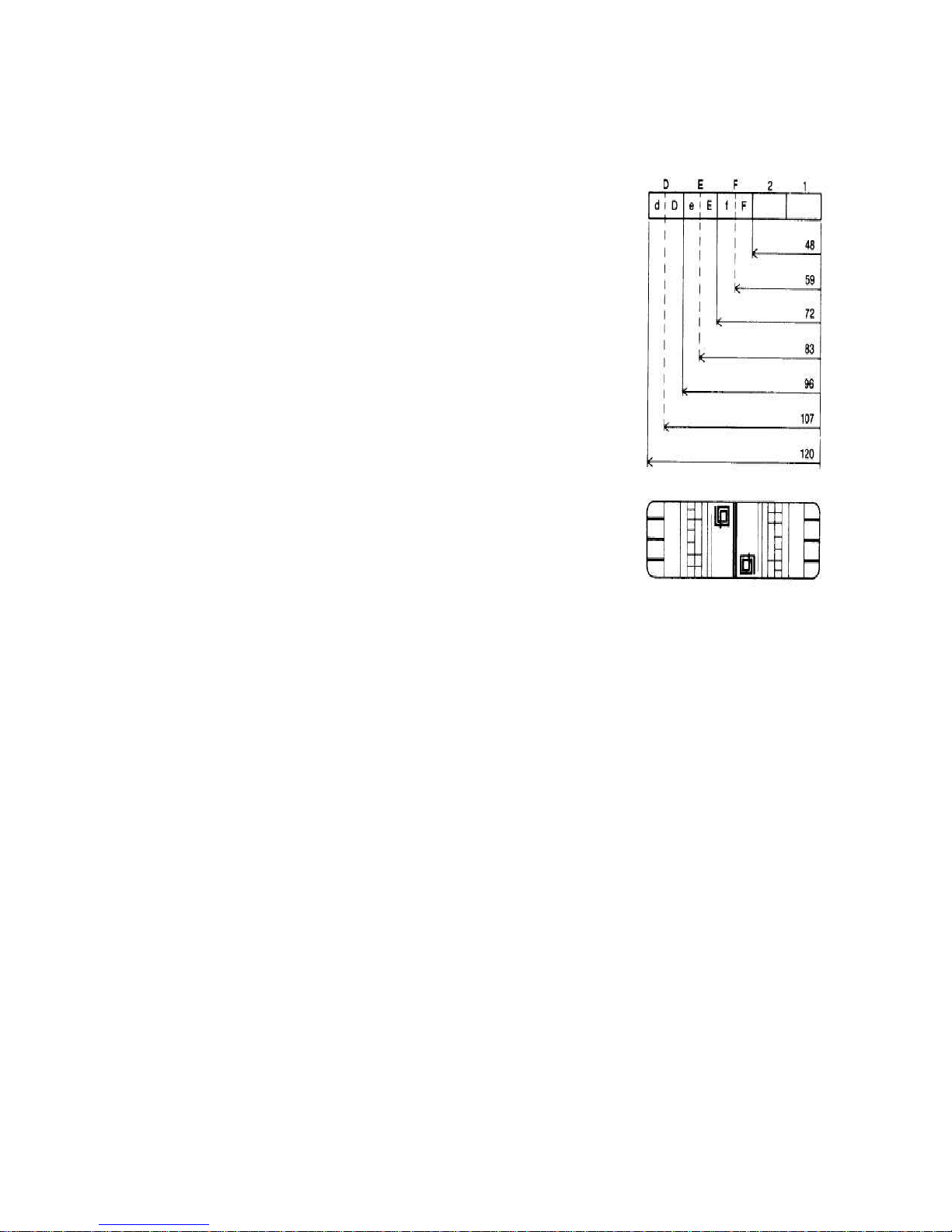
The registers F, E and D and their splits have the additional
capability of storing program instructions and constants to be used
within programs.
When these registers or their splits are used as instruction registers,
the instructions follow an overflow pattern, so that after the
instruction registers are at capacity, the remaining instructions will
be received first by F, then f, then E, then e, then D, and finally d.
Programs of up to 120 instructions can be stored internally, as
shown above. When registers D. E and F and their splits are not
used for instructions, they are free to store constants or
intermediate results.
- 7 -

The following formats show the separation and capacities of the ten registers.
Format 1 - This represents the storage registers used as complete registers: M, A, R: always
complete; B, C, D, E, F: complete in this case.
Format 2 - This represents the storage registers when split: b, B; c, C; d, D; e, E;
and f, F.
Format 3 - This represents the split registers with numeric and instruction storage: e.g. d, D;
e, E: and f, F.
Format 4 - This represents the complete instruction registers. Registers 1 and 2; registers F,
E and D when used only for instructions.
- 8 -

- 9 –

-10-

Key oard
1 The ON-OFF KEY is a dual purpose switch for both the ON and OFF positions. (Note: the
OFF position automatically clears all stored data and instructions.)
2 The ERROR (reel) LIGHT lights when the computer is turned on, and whenever the
computer detects an operational error; e.g. exceeding capacity, division by zero.
3 The GENERAL RESET KEY erases all data and instructions from the computer and turns off
the error light.
4 The CORRECT PERFORMANCE (green) LIGHT indicates the computer is functioning
properly. A steady light indicates that the computer is ready for an operator decision; a
flic ering light indicates the computer is executing programmed instructions and that the
eyboard is loc ed.
5 The DECIMAL WHEEL determines the number of decimal places to which computations will
be carried out in the A register and the decimal places in the printed output, except for results
from the R register.
8 The RECORD PROGRAM SWITCH, when ON (in), directs the computer to store
instructions either in the memory from the eyboard, or onto a magnetic program card from
the memory.
The RECORD PROGRAM SWITCH must be OFF (out) to load instructions from a magnetic
program card into the memory.
7 The PRINT PROGRAM SWITCH, when ON (in), directs the computer to print out the
instructions stored in memory from its present location in the program to the next Stop
instruction (5), whenever the Print ey (20) is depressed.
8 The MAGNETIC PROGRAM CARD is a plastic card with a ferrous oxide bac ing, used to
record programs magnetically for external storage. The card is inserted into a read/write
device (9) to record instructions and/or constants into or from the computer memory. Once
inserted, the card may be removed from the computer (10) without disturbing the stored
instructions.
(Note: the read/write device uses only half the magnetic card; consequently, two sets of 120
instructions and/or constants may be stored on a single card.) 11 The KEYBOARD RELEASE
KEY reactivates a loc ed eyboard. If two or more eys are depressed simultaneously, the
eyboard will loc to indicate a misoperation. Because the operator does not now what entry
was accepted by the computer, after touching the Keyboard Release ey the Clear Entry ey
(16) MUST next be depressed and the complete figure re-entered.
12 TAPE ADVANCE advances the paper tape.
13 TAPE RELEASE LEVER enables precise finger-tip adjustment when changing tape rolls.
- 11 -

- 12 -

14 The ROUTINE SELECTION KEYS V, W, Y and Z
direct the computer to the proper program or
subroutine.
15 The NUMERIC KEYBOARD uses the ten- ey entry
system with provision for entry of a decimal point and a
negative sign. Keyboard entries are automatically
stored in the M register.
16 The CLEAR ENTRY KEY clears the entire eyboard
entry When eying in a program, a depression of the
clear ey will erase the last instruction that has been
entered.
17 The START KEY restarts the computer in
programmed operation and is used to code a stop
instruction when eying in programs.
18 The REGISTER ADDRESS KEYS A, B, C, D, E, F
and R identify the corresponding registers. The
operating register M has no eyboard identification
since the computer automatically relates all instructions
to the M register unless instructed otherwise.
19 The SPLIT KEY combined with a register (e.g. C/)
divides that register into two equal parts. When storage
registers are split, the right portion of the split register
retains the original designation while the left side is
identified on the tape with the corresponding lower case
letter (e.g. C/ = c).
- 13 -

20 The PRINT KEY prints the contents of an
addressed register.
21 The CLEAR KEY clears the contents of an
addressed register. When the computer is operated
manually, a depression of this ey will print the number
in that register and clear it.
22 The TRANSFER KEYS perform transfer operations
between the storage registers and the operating
registers. (Refer to discussion of transfer operations for
the function of each transfer ey.)
23 The ARITHMETIC KEYS perform their indicated
arithmetic function.
- 14 -

Decimal Wheel
As it affects COMPUTATION:
The Decimal Wheel determines the number of decimal places to which
the result of a calculation in the A register will be carried out. The
Decimal Wheel has the following effect on these operations.
ADDITION, SUBTRACTION,
MULTIPLICATION:
A ter the computation, the result in the A
register is truncated according to the
number o
decimal places indicated by the
setting o the Decimal Wheel. The complete
result is retained in the R register.
DIVISION:
The quotient is retained in the A register and
is carried out only to the number o decimal
places indicated by the setting o the
Decimal Wheel.
The decimally correct remainder is retained
in the R register.
SQUARE ROOT:
The root is retained in the A register and is
extracted to the number o decimal places
indicated by the setting 01 the Decimal
Wheel.
The R registerr contains a non-
unctional
remainder.
As it effects KEYBOARD ENTRIES:
When entering decimal numbers, the Decimal Point ey is touched in its
proper position; e.g. to enter 12.6, enter 1. then 2, then touch the
Decimal Point ey, and finally enter 6.
To enter numbers less than 1, a zero must be entered before the decimal
point; e.g.07 would be entered as 0.07.
Regardless of the setting of the Decimal Wheel, the complete figure
entered on the eyboard will be printed when the Start ey or an
operation ey is touched.
As it affects OUTPUT PRINTING:
All printed output, except that of the R register, is truncated to the setting
of the Decimal Wheel.
As it affects TRANSFER OPERATIONS:
Regardless of the setting of the Decimal Wheel, the complete figure in the
selected register will be transferred.
- 15 -

Split Register
/
As was pointed out in the preceding pages, each of the B, C, 0, E and F registers can
be split into two parts, each with a capacity of 11 digits plus decimal point and sign. The left
part of the register is identified with the lower case letter corresponding to its companion's
designation. The lower case designation is obtained by entering the corresponding upper case
letter and touching the "I" ey, e.g. c = C/o The right side of the split register retains its
original upper case letter designation.
The computer has built-in self-regulating circuitry that alerts the operator with an error light if
an attempt has been made to transfer a value larger than 11 digits to a split register, or to
split a register that already contains a value greater than 11 digits.
Nevertheless. a register can be used as both a whole and a split register at varying times
throughout a program by using the clear (*) instruction before shifting from whole to split or
vice versa. For example:
In phase one of a program, register B is used as a split register (b,B); then in phase two.
register B is to be used as a whole register:
1. At the end of phase 1, a B/* instruction frees the left side of the register so that in phase
2, it can be used in conjunction with the right side as a whole register.
2. At the end of phase 2, a B* instruction frees the whole register so that it can be used as a
split register when the program starts again with phase 1.
- 16 –

General Operations
S
Start-S
The instruction "S" (used in creating a program) directs the computer to stop and release the
eyboard for the entry of figures or the selection of a subroutine. After figure entry, the
program is restarted by touching the Start ey (5).
The program can also be restarted by touching a Routine Selection ey. When the "S"
instruction stops the program, the computer may also be operated in the manual mode
without disturbing the program instructions in memory. Any figures entered on the eyboard
before depression of Start or an operation ey will be printed automatically.
*
Clear
The clear operation "*" directs the computer to clear the selected register. The M and R
registers can not be cleared with this instruction.
When the computer is operated manually this ey will also cause it to print the contents of the
selected register.
EXAMPLE: Assume register B contains 3.14159 prior to the execution of a B* instruction.
After execution of the instruction the register is blan . Note that the contents of other
registers are not affected.
______________________
M A R B
BEFORE 5.12 1.00 0.11 3.14159
B*
AFTER 5.12 1.00 0.11
Print
The print "
" operation directs the computer to print the con~nts of the selected register
while retaining them in the register. The number of decimal places in the printed result is
controlled by the Decimal Wheel.
EXAMPLE:
A
results 2.71828 A
B/
results 1.77245 b
/
Vertical Spacing
The instruction "/
" directs the computer to advance the tape one vertical space, without
printing. - 17 -

Data Transfer Operations
To A
An instruction containing the operation “
" directs the computer to transfer the contents of
the addressed register to A while retaining them in the original register. The contents of M and
R are not affected. The previous contents of A are destroyed. The setting of the Decimal Wheel
has no effect on this operation.
________________________________________________________________________________
INSTRUCTION RESULT______________________________________
M
A
R
R
A
A
Inoperative
b
b
A
B
B
A
c
c
A
C
C
A
d
d
A
D
D
A
e
e
A
E
E
A
f
f
A
F
F
A
______________________________________________________________________________
EXAMPLE: Decimal Wheel set at 2.
___________________________
M A R B
BEFORE 24 36.05 48.123 12.00
R
AFTER 24 48.123 48.123 12.00
________________________________________________________________________________
An example of using this instruction manually to transfer a value entered on the eyboara to
the A register would be to enter a figure on the eyboard (e.g. 1.141421) and then depress
the
ey. After the
ey is depressed, the data will be transferred to A and the computer
will print the number and the instruction, e.g. 1.141421
. However, if the number had been
in a register (e.g. B) and that register were directed to transfer to A, the computer would print
only the instruction, e.g. B
.
- 18 -

From M
An Insrruction containing the operation "
“ directs the computer to transfer the contents of
M to the addressed register while retaining them in M. The contents of registers A and R are
unaffected by this instruction. The original contents of the addressed register are destroyed.
The setting of the Decimal Wheel has no effect on this operation.
________________________________________________________________________________
INSTRUCTION RESULT____________________________________________
Inoperative
R
Inoperative
A
See discussion of Constants as instructions
b
M
b
B
M
B
c
M
c
C
M
C
d
M
d
D
M
D
e
M
e
E
M
E
f
M
f
F
M
F
______________________________________________________________________________
EXAMPLE: Decimal Wheel set at 2.
____________________________
M A R B
BEFORE 19.333 5.00 16.00 30.00
B
AFTER 19.333 5.00 16.00 19.333
________________________________________________________________________________
An example of using this instruction manually to store a number (e.g. 19.333) in the B
register would be to enter 19.333 on the eyboard and then depress the B and
eys. When
the
ey is depressed, the data will be transferred to B and the computer will print both the
number and the instruction executed (e.g. 19.333 B
). If B/
were then manually
performed, the same value would be transferred from M to b and the instructions would print
on the tape to indicate that the number previously entered was also transferred to b (e.g.
b
).
- 19 -

Exchange
An instruction containing the operation "" directs the computer to exchange the contents of
the A register with the contents of the addressed register. The contents of M are not affected
except by the exchange between A and M. The contents of the R register are not affected. The
setting of the Decimal Wheel has no effect on this operation.
___________________________________________________________________________________
INSTRUCTION _ RESULT_______________________________
M ⇔ A
R operates as R
(R
A)
A Absolute Value
b b ⇔ A
B B ⇔ A
c c ⇔ A
C C ⇔ A
d d ⇔ A
D D ⇔ A
e e ⇔ A
E E ⇔ A
f f ⇔ A
F F ⇔ A
___________________________________________________________________________________
EXAMPLE: Decimal Wheel set at 2.
______________________________________
M A R B _
BEFORE 6 9.0014 12.00 15.123
B
AFTER 6 15.123 12.00 9.0014
___________________________________________________________________________________
This instruction can be used manually, however , the computer will print only the adcressed register and
the instruction. e.g. C
.
- 20 -
Table of contents
Other Olivetti Desktop manuals