Olsberg 43/1481.9240 User manual

2
Die Verbrennungsluftklappe dient zum automatischen
Öffnen und Verschließen der Verbrennungsluftleitung.
Eine geschlossene Verbrennungsluftleitung verhindert
den unnötigen Warmluftaustrag aus dem Aufstellraum.
ImBetriebszustand„Aus“istdieVerbrennungsluftklappe
geschlossen, in allen anderen Betriebszuständen
(„Bereit“, „Zünden“, „Start“, ...) ist sie geöffnet.
Achtung: Zum Erreichen der Endposition „Zu“ benö-
tigt der Stellmotor ca. 2 Minuten, d.h. wenn
die Anzeige „Aus“ am Display erscheint, darf
das Gerät frühestens nach 2 Minuten am
Hauptschalter ausgeschaltet werden.
Der Einbau der Verbrennungsluftklappe darf nur durch
einen Servicetechniker erfolgen.
D
Bauteile
Fig.1 Stecker „19“ Drehkranz des Motors Anschläge für
Verbrennungsluftklappe (Auf/Zu)
Stecker „L-Dauer“
Stecker „S5“

3
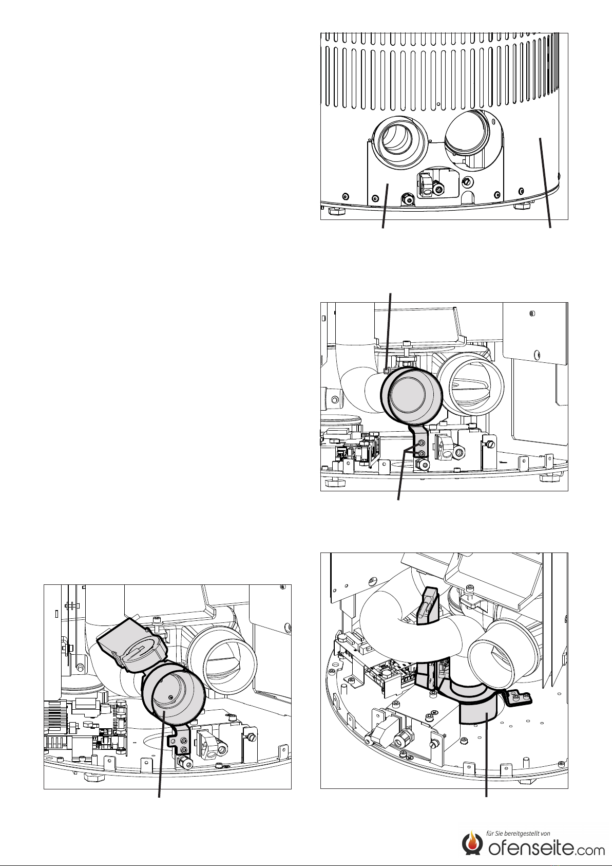
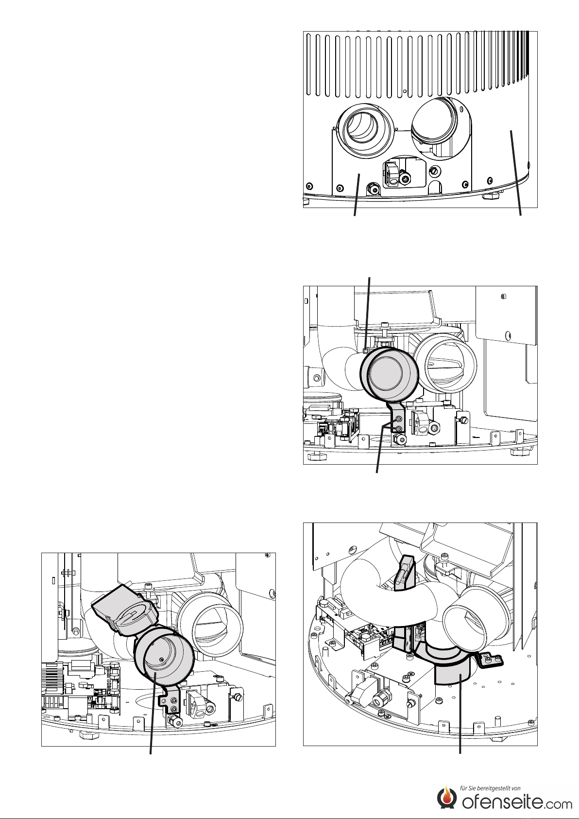
Fig.2 Blende untere Rückwand
Schlauchschelle
Fig.3 Schrauben Verbrennungsluftstutzen
Fig.5 Verbrennungsluftklappe unten angeschraubt
Montagefolge
Sollte neben der Verbrennungsluftklappe noch weite-
res Zubehör, wie z.B. GSM-Modul, montiert werden,
ist aus Gründen der Zugänglichkeit in jedem Fall als
erstes die Verbrennungsluftklappe zu montieren. Aus
demselben Grund können auch die Seitenwände erst
nach Einbau der Verbrennungsluftklappe montiert wer-
den.
●Untere Rückwand und Blende demontieren (Fig.2).
●Schlauchschelle an der Verbrennungsluftleitung lö-
sen und Verbrennungsluftstutzen entfernen (Fig.3).
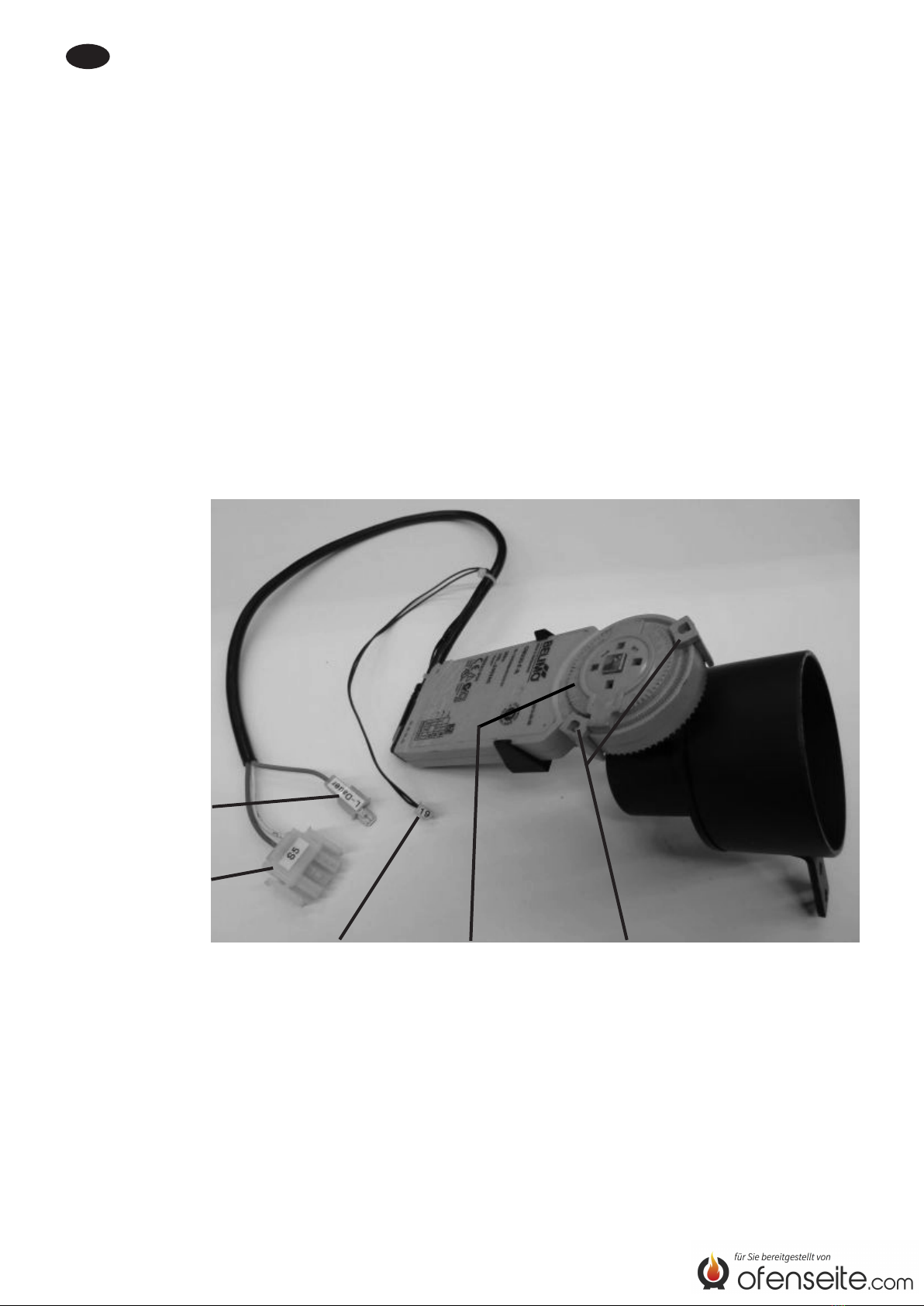
●Vor Montage die Verbrennungsluftklappe wie folgt
verdrahten:
a) Stecker „19“ auf Position „S19“ der Hauptplatine
aufstecken (siehe Anschlussplan in der unteren
Rückwand bzw. in der Geräteanleitung).
b) Stecker „S5“ auf Position „S5“ der Hauptplatine
aufstecken.
c) Stecker „L-Dauer“ auf Stecker „L-Dauer“ des
Geräte-Kabelbaums aufstecken.
●Stutzen der Verbrennungsluftklappe in Verbren-
nungsluftleitung einstecken und Schlauchschelle
wieder anziehen.
●Verbrennungsluftklappe am Gerät hinten (Fig.4)
oder unten (Fig.5) anschrauben.
● Kabel so verlegen, dass keine heißen Oberächen
berührt werden.
●Nach Montage der Verbrennungsluftklappe gewähr-
leisten, dass keine Kabel am Drehkranz des Motors
anliegen und diese beschädigt werden können.
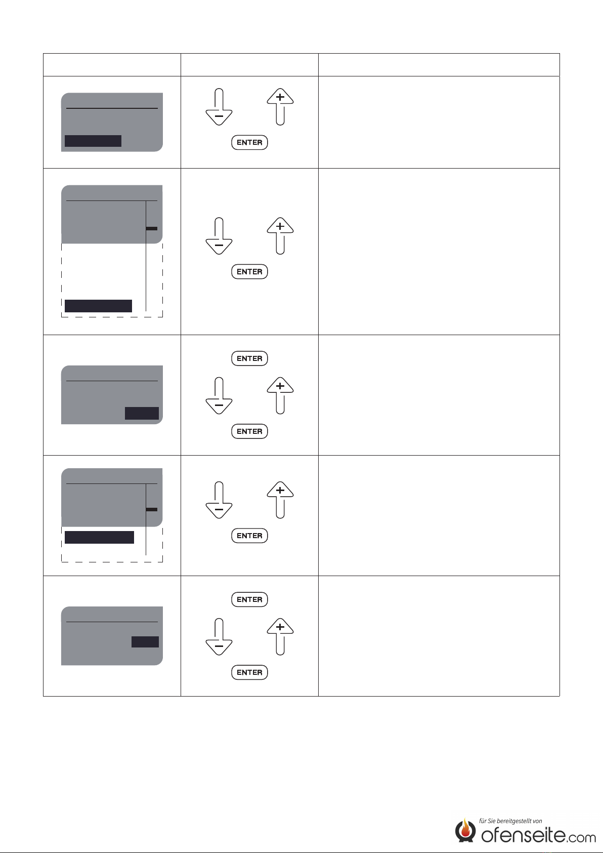
●Verbrennungsluftklappe aktivieren und auf einwand-
freie Funktion prüfen (siehe nachfolgende Kapitel).
●Blende und untere Rückwand wieder montieren.
●Wurde die Verbrennungsluftklappe unten ange-
schraubt, ist das Loch in der unteren Rückwand für
den Verbrennungsluftanschluss hinten mit Deckel
und Schrauben (liegen dem Pellet-Kaminofen bei)
zu verschließen.
Fig.4 Verbrennungsluftklappe hinten angeschraubt

4
Verbrennungsluftklappe aktivieren
Displayanzeige Aktion Beschreibung
Menüauswahl
Einstellungen
Information
Betriebsart oder
Die Verbrennungsluftklappe muss in der Service-
ebene aktiviert werden.
Über die Menüauswahl „Information“ in die Service-
ebene wechseln.
Information
Wartung
Betrstd.
Ver.
Ext.Anf.
GSM Modul
Störmeldungen
Betriebsdaten
Serviceebene
ein
n.v.
1.00.35 L6
2000h
0h oder
Serviceebene
Weiter
eingeben
Kennwort 0000 oder
Das Kennwort für die Serviceebene lautet: 2012
Serviceebene
Info Eingänge
Parameterebene
Relaistest
Komponenten
Wartung
oder
Mit ↓ oder ↑ und mit (ENTER) in das Menü
„Komponenten“ wechseln.
Komponenten
Kipprost
Zuluftklap.
Konvektion ohne
ohne
ohne
oder
„ohne“ mit (ENTER) auswählen („ohne“ blinkt) und
mit ↓ oder ↑ umstellen auf „mit“.
„mit“ mit (ENTER) bestätigen.
Die Verbrennungsluftklappe ist jetzt aktiviert.

5
Verbrennungsluftklappe auf einwandfreie Funktion prüfen
Displayanzeige Aktion Beschreibung
Serviceebene
Info Eingänge
Parameterebene
Relaistest
Komponenten
Wartung
oder
Die Verbrennungsluftklappe muss auf ein-
wandfreie Funktion geprüft werden. Dazu die
Verbrennungsluftklappe im Menü „Relaistest“ ein-
und ausschalten.
Mit ↓ oder ↑ und mit (ENTER) in das Menü „Relaistest“
wechseln.
Relaistest
Schnecke
Saugzug
Zündung
Rost
Pumpe
Zuluftklappe
Konvektion
aus
aus
aus
aus
aus
aus
oder
„aus“ mit (ENTER) auswählen („aus“ blinkt) und mit
↓ oder ↑ umstellen auf „ein“.
„ein“ mit (ENTER) bestätigen.
Funktionsprüfung durch Sichtkontrolle der Klappen-
stellung oder des Anschlags am Motor (Fig.1).

6
GB The combustion air damper is used for the automatic
opening and closing of the combustion air line. A closed
combustion air line prevents heat from being withdrawn
from the room where the appliance is set up.
The combustion air damper is closed in operation mode
„off“ and open in all other operation modes („standby“,
„ignition“, „start“, ...).
Important: It takes the servo motor approx. 2 minutes
to reach the end position „Closed“, i.e. when
the display reads „off“, you must wait for at
least 2 minutes before switching the appli-
ance off using the main switch.
The combustion air damper may only be installed by
a service technician.
Components
Fig.1 Plug “19“ Rotating assembly Stops for combustion air damper
of the motor (Open/Closed)
Plug “L-Dauer“
(“L-continuous“)
Plug “S5“

7
Fig.2 Panel Lower rear wall
Hose clamp
Fig.3 Screws combustion air duct
Fig.5 Combustion air damper screwed on
at the bottom
Installation sequence
If you want to install other accessories in addition to
the combustion air damper, e.g. a GSM module, you
always need to install the combustion air damper rst
for reasons of accessibility. For the same reason, you
can only mount the side panels after you are nished
installing the combustion air damper.
●Dismount the lower rear wall and panel (Fig.2).
●Release the hose clamp on the combustion air line
and remove the combustion air duct (Fig.3).
●Wire the plugs as follows before installing the com-
bustion air damper:
a) Connect plug „19“ onto position „S19“ of the main
circuit board (see connection diagram in the lower
rear wall / instruction manual of the pellet stove).
b) Connect plug „S5“ onto position „S5“ of the main
circuit board.
c) Connect plug „L-Dauer“ (“L continuous“) onto plug
„L-Dauer“ (“L continuous“) of the appliance‘s wir-
ing harness.
●Insert the duct of the combustion air damper into the
combustion air line and re-tighten the hose clamp.
●Screw the combustion air damper on at the rear
(Fig.4) or at the bottom (Fig.5) of the appliance.
●Route the cables in such a manner that no hot sur-
faces are touched.
●After installing the combustion air damper, avoid
damage to the cables by making sure that they do
not rest against the rotating assembly of the motor.
●Activate the combustion air damper and check it for
faultless function (see the following chapters).
●Remount the panel and lower rear wall.
●If the combustion air damper was screwed on at
the bottom, the hole in the lower rear wall for the
combustion air connection at the back needs to be
sealed with a cover and screws (are included with
the pellet stove).
Fig.4 Combustion air damper screwed on
at the rear

8
Activating the combustion air damper
Display Action Description
menu select
settings
information
operation mode or
The combustion air damper must be activated in the
service level.
Go to the service level via the menu selection, “in-
formation”.
information
service
op.hours
Ver.
ext.req.
GSM mod.
error messages
operating data
service level
on
n.c.
1.00.35 L6
2000h
0h or
Service level
next
code
enter 0000 or
The password for the service level is: 2012
service level
input data
parameter
relay
components
service
or
Go to the “components” menu using ↓ or ↑ and
(ENTER).
components
grate
supply air
convection no
no
no
or
Select “no” with (ENTER) (“no” ashes) and with
↓ or ↑ change over to “yes”.
Conrm “yes” with (ENTER).
The combustion air damper is now activated.

9
Checking the combustion air damper for faultless function
Display Action Description
service level
input data
parameter
relay
components
service
or
The combustion air damper must be checked for
faultless function. To do this, switch the combustion
air damper on and off in the “relay test” menu.
Go to the “relay test” menu using ↓ or ↑ and (ENTER).
relay test
auger
exhaust
ignition
grate
pump
supply air
convection
off
off
off
off
off
off
or
Select “off” with (ENTER) (“off” ashes), and with
↓ or ↑ change over to “on”.
Conrm “on” with (ENTER).
Check for faultless function by performing a visual
inspection of the damper position or the stop on the
motor (Fig.1).

10
FLe clapet d’air de combustion est utilisé pour l’ouver-
ture et la fermeture automatiques du conduit d‘air de
combustion. Un conduit d‘air de combustion fermé em-
pêche les déperditions de chaleur ambiante à partir de
la pièce où le poêle est mis en place.
En état de service «off», le clapet d‘air de combus-
tion est fermé, dans tous les autres états de service
(«standby», «allumer», «départ»,...) il est ouvert.
Attention: Il faut environ 2 minutes au moteur de com-
mande pour atteindre la position nale «fer-
mé», c‘est-à-dire que lorsque l‘annonce
«off» s‘afche à l‘écran, l‘appareil ne doit
être éteint qu‘au bout de 2 minutes minimum
à l‘aide de l‘interrupteur principal.
Seul un technicien de maintenance est autorisé à ins-
taller le clapet d’air de combustion.
Composants
Fig.1 Connecteur «19» Couronne d‘orientation Butées pour clapet d‘air de
du moteur combustion (ouvert / fermé)
Connecteur
«L-Dauer»
(«L-Durée»)
Connecteur «S5»

11
Fig.2 Cache Paroi arrière basse
Collier de serrage de boyau
Fig.3 Vis de manchon de raccord à l’air de combustion
Fig.5 Clapet d‘air de combustion vissé au bas
Séquences de montage
Si, outre le clapet d‘air de combustion, d‘autres acces-
soires doivent être montés, comme par ex. un module
GSM, il convient d‘installer le clapet d‘air de combus-
tion en priorité pour des raisons d‘accessibilité. Pour
la même raison, les parois latérales ne peuvent être
montées qu‘après l‘installation du clapet d‘air de com-
bustion.
●Déposer la paroi arrière basse et le cache (Fig.2).
●Desserrer le collier de serrage de boyau du conduit
d‘air de combustion et ôter les manchons de raccord
de l‘air de combustion (Fig.3).
●Avant le montage, câbler le clapet d‘air de combus-
tion comme suit:
a) Encher le connecteur «19» en position «S19»
de la carte système (voir schéma de branche-
ment sous la paroi arrière basse ou dans le ma-
nuel d‘instruction de l‘appareil).
b) Encher le connecteur «S5» en position «S5» de
la carte système.
c) Encher le connecteur «L-Dauer» («L-Durée»)
sur le connecteur «L-Dauer» («L-Durée») du fais-
ceau de câbles de l‘appareil.
● Encher le manchon du clapet d‘air de combustion
dans le conduit d‘air de combustion et resserrer le
collier de serrage de boyau.
●Visser le clapet d‘air de combustion à l‘arrière (Fig.4)
ou au bas (Fig.5) de l‘appareil.
●Câble tellement gêné qu‘il n‘y a pas des surfaces
chaudes à être touchés.
●Après le montage du clapet d‘air de combustion,
s‘assurer qu‘aucun câble ne touche la couronne
d‘orientation du moteur et ne puisse être endomma-
gé.
● Activer le clapet d’air de combustion et vérier le bon
fonctionnement (voir les chapitres suivants).
●Reposer le cache et la paroi arrière basse.
●Si le clapet d‘air de combustion a été vissé au bas
de l‘appareil, il convient de fermer l’orice prévu si-
tué dans la paroi arrière basse pour le raccordement
de l‘air de combustion à l‘aide du couvercle et des
vis (joints au poêle à pellets).
Fig.4 Clapet d‘air de combustion vissé à l‘arrière

12
Activer le clapet d’air de combustion
Afcheur Action Description
sélection menu
réglage
information
mode d‘opération ou
Le clapet d’air de combustion doit être activée dans
le menu SAV.
Passer au menu SAV depuis la sélection du menu
«information».
information
service
heures
Ver.
therm ext.
mod. GSM
info d‘erreurs
information
menu SAV
on
n.i.
1.00.35 L6
2000h
0h ou
menu SAV
suiv.
code
entrer 0000 ou
Le mot de passe pour le menu SAV est: 2012.
menu SAV
info
paramètres
test sortie
accessoire
service
ou
Passer au menu «accessoire» avec ↓ ou ↑ et avec
ENTER.
accessoire
grille
air combust
convection non
non
non
ou
Sélectionner «non» avec ENTER («non» se met à
clignoter) pour le mettre à «oui» avec ↓ ou ↑.
Conrmer «oui» avec ENTER.
Maintenant, le clapet d’air de combustion est acti-
vée.

13
Vérier le bon fonctionnement du clapet d’air de combustion
Afcheur Action Description
menu SAV
info
paramètres
test sortie
accessoire
service
ou
Le bon fonctionnement du clapet d’air de combus-
tion doit être vérié. Pour ceci, allumer et éteindre le
clapet d’air de combustion dans le menu «test sor-
tie».
Passer au menu «test sortie» avec ↓ ou ↑ et avec
ENTER.
test sortie
vis sans fin
extracteur
allumage
grille
pompe
air combustion
convection
off
off
off
off
off
off
ou
Sélectionner «off» avec ENTER («off» se met à cli-
gnoter) pour le mettre à «on» avec ↓ ou ↑.
Conrmer «on» avec ENTER.
Essai fonctionnel visuel de la position du clapet ou
de la butée du moteur (Fig.1).
Table of contents
Languages:
Other Olsberg Fan manuals