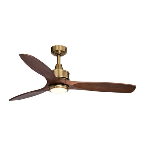
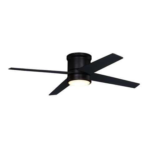
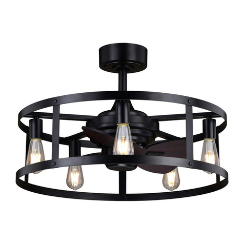
Vaxcel F0095 User manual

PAGE: 1 / 11
Model No.: F0095
LIMITED LIFETIME WARRANTY
ORIGINAL VAXCEL CEILING FAN LIMITED LIFETIME WARRANTY
The limited lifetime warranty covers this fan, for residential use by the original purchaser, against defects in material or
workmanship as follows:
If your fan motor fails at any time during the lifetime of the original purchaser due to defects in material or workmanship,
we will provide a replacement part free of charge.
If your fan motor fails at any time within one year after the original date of sale to the original purchaser due to defects
in material or workmanship, we will provide labor to repair the defect, with the exception of take down/reinstallation,
free of charge. The original purchaser will be responsible for all labor costs after this one year period.
If no replacement parts are provided for any part of your fan motor that fails at any time during your lifetime due to
defects in material or workmanship, we will refund the original purchase price of your fan.
If your fan blades, or any accessory, except glass globes and light bulbs, fails at any time within one year after the
original date of purchase due to a defect in material and workmanship, we will repair or, if we choose, replace the
defective blades, switch, or accessory free of charge, with the exception of take down/reinstallation services.
If the original purchaser ceases to own the fan, this warranty and any implied warranty, including but not limited to any
implied warranty of merchantability or fitness for a particular purpose, become void. This warranty and any implied
warranty, including but not limited to any implied warranty of merchantability or fitness for a particular purpose, do not
cover glass globes, light bulbs, or finish on any metal portions of the fan.
This warranty is in lieu of express warranties. The duration of any implied warranty of merchantability or fitness for a
particular purpose, with respect to any fan motor, blades, switch, or accessories, is expressly limited to the period of the
express warranty set forth above for such motor, blades, switch, or accessories.
This warranty excludes defects, malfunctions, or failures of any fan that are caused by repairs by persons not authorized
by us, use of parts or accessories not authorized by us, mishandling, improper installation, modifications or damage to
the fan while in your possession, or unreasonable use, including failure to provide necessary maintenance.
In no event shall VAXCEL be liable for consequential or incidental damages.
Some states do not allow the exclusion or limitation of consequential or incidental damages, in which case the above
limitation or exclusion may not apply.
This warranty gives you specific legal rights and you may also have other rights which vary from state to state.
220829

PAGE: 2 / 11
Remote
Control
Instructions
X 9
1 2 3 4
5
6
789
10 11 1312
Unpack your fan and check the contents. You should have the following items.
1.) Hanger Bracket
2.) Canopy
3.) Decorative Cap (Remove the Preassembled Decorative Cap from the Canopy Before Installation.)
4.) Downrod Stand Cover
5.) Downrod Set (Included Hanger Ball, 6” Downrod, Hanger Pin & Lock Pin)
6.) Fan Motor Assembly
7.) Fan Blades (2 PCS)
8.) Connect Plate of Light Kit
9.) Light Kit with LED Module
10.) Glass Shade
11.) Assembly Kit
12.) Remote Control Set (Includes Receiver & Transmitter & Wire Connectors & Battery
& Screws & Remote Control Instructions)
13.) Installation Instructions
Dimension Reference (Installed with 6" Downrod):
A. 16" B. 12-1/2" C.52" D. 5"
C
A
B
D
220829

PAGE: 3 / 11
Hanger Bracket
Hanger Ball
Canopy
Decorative Cap
Lock Pin
Fan Motor Assembly
Connect Plate of Light Kit
Downrod Stand Cover
Hang Pin
Collar
Fan Blade
Light Kit with LED Module
Glass Shade
220829

PAGE: 4 / 11
220829

PAGE: 5 / 11
IMPORTANT:
BEFORE YOU BEGIN INSTALLATION, CAREFULLY READ ALL INFORMATION PROVIDED IN THE SAFETY
INSTRUCTIONS AND INSTALLATION INSTRUCTIONS. IF IN DOUBT, CONSULT A QUALIFIED
ELECTRICIAN.
SAVE ALL INSTRUCTIONS.
Tighten the two collar screws.
Slide lock pin into hanger pin until
it is locked into position.
Turn OFF the electric circuit at the
main fuse fuse or circuit breaker
box.
Hang the fan on hanger bracket, and
make sure the slot of hanger ball is
snapped into the chip of hanger bracket
exactly.
Note: For sloped ceiling installation,
make sure the slot of hanger ball and
the chip of hanger bracket face down.
Lock Pin Collar Screws
NOTE: The fan weight is 10.69 lbs (4.85 kg). Be sure the outlet box you are using is securely attached to the building
structure and can support the full weight of the fan. Failing to do so can result in serious injury.
Remove the lock pin from the
hanger pin and remove the
hanger pin from the downrod.
Thread the motor wires through the
downrod stand cover, decorative cap
(Making sure the smooth side of
decorative cap is facing downward.),
canopy and downrod.
Loosen the collar screws out part way.
Insert the downrod into the collar.
Slide hanger pin through holes of
collar and downrod.
Downrod
Tighten the hanger bracket to the outlet box with two mounting screws.(Make sure
the outlet box is securely installed so that it will be able to support at least
the fan weight.) Attach the safety cable hook to the ceiling with the drywall screw
and washer, and make sure the safety cable hook is covered by the fan canopy.
WARNING: MOUNT ONLY TO AN OUTLET BOX MARKED "ACCEPTABLE FOR
FAN SUPPORT"!
Washer
Safety Cable Hook
Dry Wall Screw
Ceiling
Hanger Bracket
Ceiling Joist
Wood Member
(2" x 4" Approx.)
Junction Box
Fig.5.
Ceiling
Hanger Bracket
Ceiling Joist
Wood Member
(2" x 4" Approx.)
Junction Box
Fig.2
Stand Cover
Hanger Pin
Stand Cover
Downrod
220829

PAGE: 6 / 11
After making the wire connections, the wires should
be spread apart. The white (neutral) conductor from
receiver and outlet box with green (grounding)
conductor on one side; the black (hot) conductor
from receiver and outlet box with the white, black
and blue conductor from receiver and motor on the
other side of the outlet box.
Move ground wires (a), outlet box wires (b), and motor
wires (c) away from the center of the hanger bracket.
Then slide receiver through hanger bracket as shown.
Antenna end first, until it is centered. Finally, cut motor
wires (c) to length needed for connections.
G
Code example:
1-ON 2-OFF 3-ON 4-OFF on both SUR
Switches.
Note: If you have two ceiling fans with
2 remote control units, set 2 different
codes for each set of transmitter / receiver.
220829
Both the transmitter and receiver have a 4-key
unit code on each SUR Switch (Fig.8) and by
default, all keys are pre-set to the "off" position.
This means that the transmitter and receiver are
already paired together. However, if you have
multiple fans and remote controls and want to
avoid interference between them, you can "pair"
other transmitters and receivers together by
adjusting the SUR switches, so the same
numbered keys are in the "ON" position
on both (Fig.8a).
Note: The ceiling fan may work abnormally
if there is interference from other remote
controls.
Hanger Bracket
Receiver
Antenna
SUR
ON
SUR
ON SUR

PAGE: 7 / 11
Fig.18
Remove three screws from connect plate of light kit first. Then
connect the white (neutral) wire from the light kit to white
(neutral) wire from connect plate of light kit with a wire connector;
connect the black (hot) wire from light kit to blue (hot) wire from
connect plate of light kit with a wire connector. Carefully put the
wires into the connect plate of light kit, then attach the light kit
onto the connect plate of light kit with the connect plate screws.
Washer
Screw
Hanger Bracket
Canopy
Fig.12
Blade
Fan Motor
Assembly
Blade Screws
Fig.13
Stud
Slot
Glass Shade
Fig.16
Light Kit
Attach the glass shade to the
light kit by aligning studs and
slots, and turn clockwise until
it is locked in place.
There are four hanger bracket screws and lock washers.
Remove two screws and lock washers from the hanger
bracket (one from each side) and loosen the other two
remaining screws. Align the “L shaped” slots of the
canopy with the two remaining screws on the hanger
bracket and push the canopy upwards to engage the
slots and turn clockwise to lock in place. Tighten the
screws and install the other two hanger bracket
screws and lock washers into the remaining
holes of the canopy and tighten.
Remove one screw and loosen another two screws
from fan motor assembly first, then thread the fan motor
assembly wires through connect plate of light kit, then
push the connect plate of light kit upwards until the
fan motor assembly screws insert into the key hole
slots of connect plate of light kit, then rotate the connect
plate of light kit until it’s fixed on the fan motor assembly
bottom. Finally, secure the connect plate of light kit to
the fan motor assembly bottom with previous screw which
was removed. Tighten the other two fan motor assembly screws.
Align the holes on one of the blades with the holes on the
bottom of fan motor assembly, then loosely attach the blade
using the screws provided. Repeat this process for the second
blade. Once both blades are in position and connected with
blade screws firmly tighten all screws.
NOTE: Before installing blades to the motor, please
remove the plastic inserts.
Fan Motor Assembly
Fix Screw
Connect Plate of Light Kit
Connect
Plate of
Light Kit
Light Kit
Connect Plate Screws
Hang the safety cable into the safety cable hook. (See Fig.11)
Fig.11
Safety Cable Hook
Safety
Cable
Fig.14
Fig.15
Fig.17
Reverse
Slide Switch
Forward
The slide switch on motor
assembly sets direction of fan
rotation.Select the desired
direction of fan rotation. Push the
slide switch left for "Forward" and
right for "Reverse".
Note: Wait for fan to stop before
reversing the direction of blade
rotation. Turn ON the electric circuit
at the main fuse or circuit
breaker box.
220829

PAGE: 8 / 11
Note: 1. Remote controller can not be used along with a solid-state speed control at the same time.
2. The temperature and brightness of light can not be set without remote controller.
Fig.19
HI
MED
LIGHT
0N/0FF DIMMER
FAN OFF
LOW
Install the battery (9V, included) into the transmitter.
* Press "HI" button to turn on the fan at high speed.
* Press "MED" button to turn the fan in medium speed.
* Press "LOW" button to turn the fan in low speed.
* Press "FAN OFF" button to turn off the fan.
* Press "LIGHT ON /OFF" button to turn on or turn off the light.
* Press and hold the "DIMMER" button to dim or brighten lights to the desired level and
release, and the brightness level will be memorized. Turn on the light again, then fan
light will be restored to the brightness-level at which it was dimmed last time.
* Press "DIMMER" button to change color temperature of fan light, there are a total of 5
levels of color changing from 2700K,3000K,3500K,4000K to 5000K.
Note:
1. This remote controller has a memory function setting. The fan will operate at the same
speed and the fan light will stay at the same brightness-level as the last time the power
supply was turned off.
2. Compatible Wall Switch: Lutron SKU# DVFSQ-LFH-WH.
a. Warning: This wall switch is not capable of changing the temperature and brightness
of the light. Therefore, it’s important to set your preferred color temperature and
brightness before removing the remote-control receiver from the fan.
b. This LED module has a memory function setting. The fan light will stay at the same
brightness and temperature as the last time of remote control setting. To proceed
with installation without remote control, please start from Fig.20.
Transmitter
Wall Bracket
Screw
19
Install the transmitter wall bracket on the wall with two screws
and place transmitter in it carefully.
Fig.22
Fig.20
Fig.21
21
22
220829

PAGE: 9 / 11
Fig.23
Fig.24
Fig.25
220829

PAGE: 10 / 11
too tight
If you have difficulty operating your new ceiling fan, it may be the result of incorrect assembly, installation
or wiring. In some cases, these installation errors may be mistaken for defects. If you experience any
faults, please check this Troubleshooting Guide. If a problem cannot be remedied or you are
experiencing difficulty in installation, please call our Customer Service Department (1-800-482-9235).
220829

PAGE: 11 / 11
220829
Other Vaxcel Fan manuals
Popular Fan manuals by other brands

SOLIS
SOLIS TRIPLE FAN PLUS user manual

Klimawent
Klimawent BULLET-160-N Use and maintenance manual

Three Sixty
Three Sixty The Tropicana TRO54 Series owner's manual

Bosch
Bosch DRC97AQ50 User manual and assembly instructions

Greenwood
Greenwood Vireo HR155WM installation instructions

Ebmpapst
Ebmpapst 4606 ZH operating manual