Olympus BH2-TET Operating instructions

QUADRUPLEOBSERVATIONTUBE
BH2-TET
REPAIRMANUAL
OLYMPUS

BH2-TET
INTRODUCTION
1. Pay attention to the following points when using this manual.
@ This manual describes assembly and adjustment of the connecting
tube of BH2-TET. For adjustment of BI and TRC part, refer to the
following manuals.
(1) BH2-B130 Repair Manual
(2) BH2-TR30 Repair Manual
BH2-B130 Repair Manual
0
Adjustment part explained in this manual
Adjustment of optical .axis and
parfocality of straight tube
Adjustment of optical axis and
parfocality of connecting tube
.
Positioning of beam splitter Adjustment of
mirror
inclination

BH2-TET
CONTENTS
A, OUTLINEOFPRODUCT
1, OUTLINE___________-____________________-_____
A-2
2, FEATURES
-------------------------------------
A-2
3, USINGCONDITIONS---_------_-________-~~~~~~~~A-2
4,
SPECIFICATIONS -_-_____________-___----------- A-3
B, DISASSEMBLYPROCEDURE
1, DISASSEMBLY PROCEDURE ------------------------ B-2
C, ASSEMBLYANDADJUSTMENT
1, ASSEMBLYOFEACHPART
------------------------
c-2
2, TENTATIVEASSEMBLY
---------------------------
c-3
3, ADJUSTMENT
OFSTRAIGHTTUBE------------------ C-6
4, ADJUSTMENTOFCONNECTINGTUBE---------------- c-8
Do JIGS,TOOLSANDADHESIVES
1, ADHESIVES
------------------------------------
D-2
2, JIGSANDTOOLS
----------------_-_------------
D-3

BHZ-TET A. OUTLINE OF PRODUCT
CONTENTS
1, OUTLINE
-------------------------------------------
A-2
2, FEATURES
------_-----------_----------------------
A-2
3, USINGCONDITIONS________-__________-------------A-2
4, SpE(-IFI(-ATIONS-____-____-_-__---__---------------A-3
A-l

BHZ-TET A. OUTLINE OF PRODUCT
11, OUTLINE I
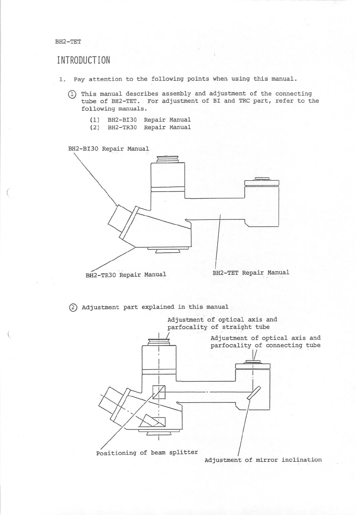
This is the quadruple observation tube having binocular tube of 30°
inclination angle (fixed) used for the system microscope BH2 series,
straight tube used as an optical path for photomicrography or TV
camera and connecting tube used as an optical path for TV camera
with straight tube.
12. FEATURES I
(1) Left and right diopter differences can be corrected with the
helicoid ring of one side.
(2) Optical paths are independent for photomicrography and TV camera,
respectively, enabling simultaneous photography with TV monitor
image.
(3) Use of mold preventive agent suppresses generation of mold,
offering a good observation image.
13, USINGCONDITIONS
(1) Unusable with BH2 accessories BH2-DO (including MD01
I BH~-SPS (including MPS)
(2) Only the C-mount type TV camera can be mounted on the connecting
tube.
Mountable TV camera: C-mount type TV camera, 2kg or less
(3) The PM photomicrographic system or TV camera system can be
mounted on the straight tube.
(4) When the PM photomicrographic system is mounted on the straight tube,
the connection cable of the PM photomicrographic system interferes with
the TV camera system with a certain size mounted on the connecting tube.
* TV camera size mountable on the connecting tube:045 x 70mmmax.
(avoided with the exclusive cable)
A-2

BH2-TET A. OUTLINE DF PRODUCT
4, SPECIFICATIONS I
Item
1 Observation tube
inclination angle
Specification Remarks
300
2 Field number 21 (16 in the connecting tube) *75%
3 Interpupillary 53 - 75mm
distance adjustment
range
4 Optical axis Parallel axis
5 Left/right diopter Sleeve-L with diopter adjustment ring
difference correction (correction range +5 diopter)
6 Photomicrographic PM mount
system mount
7 TV camera system
'mount Straight tube: C-mount type TV camera
is mounted through MTV3.
Connecting tube: C-mount type TV camera
is directly mounted.
8 Light path selection Selectable in 3 steps
(Light intensity selection is impossible
on the optical path of the
straight tube and the connecting tube.
:9 Weight
Binocular 0% 20% 100%
Straight tube 50% + 40% + 0%
Connecting tube 50% 40% 0%
l
2.7kg
A-3

BH2-TET B. DISASSEMBLY PROCEDURE
CoNTENTS
1, DISASSEMBLYPROCEDURE
------
----------------_------
B-2
c
B-l

BH2-TET B. DISASSEMBLY PROCEDURF:
11, DISASSEMBLYPROCEDURE
0
Disassemble the mount part of
CONNECTINGTUBE as illustrated
on the left.
Screw AB3x14SA 3 PCS.
0
Remove the PLATE 0 (stuck with
a double coated tape) of the
CONNECTINGTUBE with care taken
not to bend it.
@ Remove the MIRROR MOUNT@.
Screw CUK3x8SA 3 PCS.
69 Remove the MIRROR@ (stuck with
the silicon type adhesive).
@ Remove the CONNECTINGTUBEa
from the STRAIGHT TUBE.
Screw AB4x35SA 4 PCS.
G9 Remove the PRISM@ (fixed with
the epoxy type adhesive).
B-2

BH2-TET B. DISASSEMBLY PROCEDURE
G3
H
v
0
0 -
-1
0‘.
e3
8
0
0
0
1
Remove the PRISM MOUNT@from
the CONNECTINGTUBE.
Screw ANU3x4SA 2 PCS.
Remove the RING@from the
PRISM MOUNTa, and take off
the lens 0.
Remove the LENS FRAME@from
the CONNECTINGTUBE.
Adjustable spanner (TETKC02)
Remove the RINGafrom the LENS
FRAME@, and take off the LENS@.
Disassemble the STRAIGHT TUBE.
Screw AB3x45SA 3 PCS.
B-3

BH2-TET C. ASSEMBLYAND ADJUSTMENT
CONTENTS
1, ASSEMBLY OF EACH PART __--- __~~~~~__~___~~~~~_ -_---_
c-2
2, TENTATIVEASSEMBLY
_-------------------------------- c-3
3, ADJUSTMENTOFSTRAIGHTTUBE----------------------- C-6
4, ADJUSTMENTOFCONNECTINGTUBE-------------------- C-8
C-l

BH2-TET C. ASSEMBLYAND ADJUSTMENT
11, ASSEMBLYOF EACHPART
l-l Bond the PRISMat the PRISM MOUNTa.
(1) Place the PRISM@on the PRISM
MOUNTO.
* Pay attention to the direction
(2) Push the PRISM@in the arrow
direction, and adjust the dimen-
sion A to 0.5mm (measure with a
0
clearance gauge).
(3) Secure the PRISM@with the SCREW
01 and apply the adhesive to the
mounting surface of PRISM MOUNTa
and the PRISM@.
Adhesive Araldite rapid (OT1315)
l-2 Bond the MIRROR@totheMIRROR MOUNTa.
(1) Place the MIRROR@on the MIRROR
MOUNTawith the mirror surface
up.
(2) Apply the adhesive to the mounting
surface of MIRROR MOUNTand the
MIRROR.
Adhesive SE9156 (OT1538)
l-3 Fit the LENS@into the LENS FRAME
0
1 in the correct direction, and
tighten the RING 0.
l-4 Fit the LENS@into the PRISM MOUNT
ain the correct direction, and
tighten the RING@.
c-2

BH2-TET C. ASSEMBLYAND ADJUSTMENT
1 2, TENTATIVEASSEMBLY
2-l Screw the LENS FF!AME@in the
CONNECTINGTUBE@.
Adjustable spanner (TETKC02)
2-2 Insert the PRISM MOUNT@all the
way into the CONNECTINGTUBE@.
(Do not fix it.)
Secure the MIRROR MOUNTOtentative-
ly to the CONNECTINGTUBE@.
Screw CUK3x8SA 3 PCS.
c-3

BH2-TET C. ASSEMBLYAND ADJUSTMENT
@-&
2-4 Place the WASHERDon the
mount part of CONNECTINGTUBE@.
* Standard thickness of WASHER
t=0.5mm
2-5 Secure the SPACER@firmly.
* Place the SPACEROagainst the
mount part of CONNECTINGTUBE@
even.
Screw AB3x14SA 3 PCS.
!’
2-6 Fit the FILTER@into the SPACER
0, and secure it with the SPRING@.
2-7 Place the SPACER@, WASHER@and
MOUNT@on the STRAIGHT TUBE, and
secure them. t
Screw AB3x45SA 3 PCS. f
* Standard thickness of WASHER
t=o.smm
c-4

BH2-TET C. ASSEMBLYAND ADJUSTMENT
2-8 Assemble the CONNECTINGTUBE @
tentatively.
Screw AB3x35SA 4 PCS.
.. .
_’ ,:
.
c-5

BH2-TET C. ASSEMBLYAND ADJUSTMENT
[ 3, ADJUSTMENTOFSTRAIGHTTUBE
3-l Adjustment of parfocality
(1) Set the jigs.
@)Microscope stand (adjusted)
@Universal standard eyepiece
(KNOO48)
@FT36 (or KNO025) . -
@Specimen easy to focus
~ lpm @Objective 10x
(2) Adjust the focus to the specimen.
\ /
B
(Move the stage up or down.)
(3) Put the eyepiece to the STRAIGHT
TUBE.
(4) Adjustathe focus to the specimen
at the right tube of BI. (Turn
the helicoid ring.)
(5) Read the displacement of optical
tube length from the eyepiece
scale@.
scale corresponds to O.lmm in
if the displacement reduces in
the direction of pulling out
the helicoid ring of the eye-
(6) Increase or decrease the thicknessof
WASHER@, and check again the
optical tube length.
(7) If the optical tube length is out
of the standard, repeat adjustment
from (5).
3-2 Adjustment of the optical axis
(1) Set the jigs in the same way as
in "3-l Adjustment of parfocality".
Change only the specimen.
Specimen
- l/100 cross micrometer
(2) Adjust the center cross
hairs of the eyepiece fit into
the SLEEVE-R to the center of
the cross micrometer.
(move the stage)
C-6

BH2-TET
C.
ASSEMBLYANDADJUSTMENT
* After the adjustment, take care
not-to move the cross micrometer
position.
(3) Put the eyepiece to the STRAIGHT
TUBE.
(4) Adjust the center cross
hairs of the eyepiece to the
center of the cross micrometer
by loosening the screw and
displacing the MOUNTO .
(5) Tighten the screw securely.
(6) Check the optical axis between
BINOCULARTUBE
and STRAIGHTTUBE
for displacement.
(7) If the displacement is out of
the standard, repeat adjustment
from (2).
c-7

BH2-TET C- ASSEMBLYAND ADJUSTMENT
4, ADJUSTMENTOFCONNECTINGTUBE
4-l Adjustment of exit pupil
(1) Set the jigs.
O'Microscope stand (adjusted)
2 Centering telescope (KN0029)
8
3 l/100 cross micrometer
4 Eyepiece adapter (TETKCOl)
8
5 DAchlOx
@ universal standard eyepiece
(KNOO48)
(2) Look through the centering tele-
scope and twist the CONNECTING
TUBEato minimize displacement
of the exit pupil.
(3) Tighten the screw to fix the
CONNECTINGTUBEa.
(4) Look through the centering tele-
i!!i!iQ
scope and move the MIRROR MOUNT
ain the screw play range to
;, ) minim&e displacement of the
exit pupil.
J) Tighten the screw to fix the
MIRROR MOUNT@.
C-8

BH2-TET C. ASSEMBLYAND ADJUSTMENT
i
if the displacement reduces in
the direction of pulling out the
(6) Increase or decrease the thicknessof
WASHER@, and check again the
(1 graduation of eyepiece scale)
(6)
Adjust the center cross hairs
of the eyepiece fit into the
SLEEVE-R
to the center of the
cross micrometer. (By moving the
stage)
* After the adjustment, take care
>I
(7)
Put the eyepiece to the CONNECTING
TUBE, and confirm that the displace-
ment of the optical axis between
BINOCULAR TUBE and CONNECTINGTUBE
is less than 5 graduations (0.5mm).
(8) If the displacement is over 5
graduations, repeat adjustment
from (4).
1;
4-2 Adjustment of parfocality
(1) Set the jigs.
1 Microscope stand (adjusted)
8
2 Universal standard eyepiece
(KNO048)
@Eyepiece adapter (TETKCOl)
@FT36 (or KNOO25)
@Specimen easy to focus
(2) Adjust the focus to the specimen at
the right tube of BI. (Move the
stage up or down.)
(3) Put the eyepiece to the CONNECT-
ING TUBE.
(4) Adjust@the focus to the specimen.
(Turn the helicoid ring.)
(5) Read the displacement of optical
tube length from the eyepiece
c-9

BH2-TET C. ASSEMBLYAND ADJUSTMENT
(7) If the optical tube length is out
of the standard, repeat adjustment
from (5).
4-3 Adjustment of the optical axis
(1) Set the jigs in the same way as
in "4-2 Adjustment of parfocality".
Change only the specimen.
Specimen
. l/100 cross micrometer
(2) Adjust the center cross hairs
of the eyepiece fit into the
SLEEVE-R to the center of the
cross micrometer.
(move the stage)
* After the adjustment, take care
[I
(3) Put the eyepiece to the CONNECTING
TUBE.
(4) Adjust the center cross hairs
of the eyepiece to the center
of the cross micrometer by loosen-
ing the screw and displacing the
SPACER@.
(5) Tighten the screw securely.
(6) Check the optical axis between
BINOCULAR TUBE and CONNECTING
TUBE for displacement.
@I
(7) If the displacement is out of
the standard, repeat adjustment
from (2).
c-10

.
BH2-TET C. ASSEMBLYANDADJUSTMENT
4-4
4-5 Stick dn the PLATEa.
4-6 Mount the C-MOUNT@.
Apply the adhesive to the fixing
screw of SPACER@).
Adhesive Shellac (OT1131)
i.
c-11
Table of contents
Other Olympus Telescope manuals
Popular Telescope manuals by other brands

SKY-WATCHER
SKY-WATCHER LightChariot 80AR-AZ instruction manual

Celestron
Celestron FIRSTSCOPE 114 31048 instruction manual

Orion
Orion StarBlast 4.5 user manual

Bresser
Bresser National Geographic 76/700 EQ operating instructions

Meade
Meade RB-60 instruction manual

Bushnell
Bushnell HARBORMASTER 78-6035 user manual