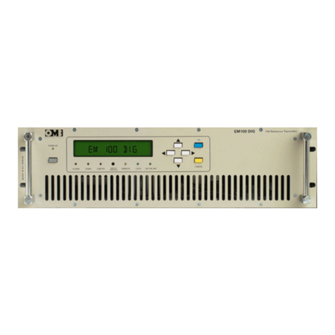
OMB EM 1000 HE DIG PLUS COMPACT User manual

TECHNICAL MANUAL
v1.2 November 2019
F
FM
M
B
BR
RO
OA
AD
DC
CA
AS
ST
T
T
TR
RA
AN
NS
SM
MI
IT
TT
TE
ER
R
E
EM
M
1
10
00
00
0
H
HE
E
D
DI
IG
G
P
PL
LU
US
S
C
CO
OM
MP
PA
AC
CT
T
TECHNICAL MANUA
L
v1
.2
No
v
e
m
be
r
2
01
9
OMB EUROPE OMB USA
Polígono Industrial Centrovía
Calle Paraguay, 6
50198 - La Muela
Zaragoza, ESPAÑA
3100 NW 72nd. Avenue Unit 112
MIAMI, Florida 33122 USA
Telf.: (305) 477 0973
(305) 477 0974
Fax: (305) 477 0611
Web: www.omb.com
E-mail: europa@omb.com
Web: www.omb.com
E-mail: usa@omb.com
Telf. : +34 976 14 17 17
Fax: +34 976 14 17 18

OMB ESPAÑA
Polígono Industrial Centrovía
Calle Paraguay, 6
50198 – La Muela
Zaragoza (ESPAÑA)
Ph: +34 976 14 17 17
Fax: +34 976 14 17 18
Web: www.omb.es
E-mail: [email protected]m

LIMITED WARRANTY
About Installation
1. – The mains voltage must be kept between ±10% of its nominal value, unless
otherwise specified. If there are variations exceeding this tolerance, it will be
necessary to install a voltage stabilizer system within the station. If transient
over voltages due to electric motors or other devices of this sort connected to
the distribution line were present, or if the distribution line is exposed to
atmospheric electrical discharges, it must be indispensable the installation of
isolation transformers and gaseous dischargers before connecting any
equipment within the station.
2. - All equipments must be connected to the station ground system in order to
avoid damage, both for equipments and for maintenance personnel. It is
necessary to connect a differential automatic switch (lifesaver) at the station.
3. - Some equipments do not include interlock protection for open doors, covers
or connectors. In that case, these equipments must be kept in key–locked
places with access only to conveniently qualified personnel that are previously
advised about not opening doors, covers or connectors without disconnecting
the station mains switch before performing this job.
4. - Transmission equipments will NEVER be operated with an output power
higher than its nominal values, or with signals or input information different than
those specified in its individual characteristics.
5. - Ambient temperature inside the equipments' room will accomplish the
technical specifications of the equipments installed at the station lodge. In
absence of such specifications, maximum allowable temperatures will be from -
5 to +45ºC for television equipments, and from 0 to +40ºC for FM broadcast
equipments.
6. - In case of operation at abnormally high or extremely high temperatures
(over 30-40ºC), it is mandatory to install a forced cooling system that will keep
temperature below its upper limit. In case of operation at abnormally or
extremely low temperatures, it will be mandatory to install a thermostatic
controlled heating system for the equipment's room.
7. - The equipment’s surroundings and room must be free of dust and dirt.
Ambient relative humidity will be kept below equipment's extreme specifications.
In case of absence of this specification, allowable maximum will be 90% of
relative humidity non-condensing. Average relative humidity will be kept under
70% non-condensing.
8. - Every transmission equipment that can radiate some quantity of RF power
must be connected to a load or antenna system according to their individual
specifications before being energized.
9. - Maximum allowable VSWR in antenna systems both for TV or FM Radio
Broadcast operation of a given transmitter will be 1.25:1, unless otherwise
specified.

10. - Periodically, monthly as a maximum, technical personnel must visit the
station in order to perform a general equipment maintenance unless otherwise
specified. This maintenance will include checking the output power, VSWR of
antenna systems, forced cooling or heating systems for the equipments and for
the station itself, including cleaning of air filters, measuring the transmission
frequency with eventual correction if necessary, and performing a general check
of fundamental parameters of the equipments. In the event of any important
change in some operation parameters that will require replacement or
readjustment of any unit, the customer MUST CONTACT FIRST WITH OMB
SISTEMAS ELECTRONICOS, S.A. BEFORE ANY ATTEMPT TO READJUST
OR REPLACE ANY COMPONENT OR UNIT INSIDE THE EQUIPMENTS IN
ORDER TO KEEP VALID THIS WARRANTY.
11. - For devices in fixed racks or cabinets, they must be effectively connected
according to the International Installations Standards to the station ground
system, which its total impedance measured to ground cannot be higher than 5
ohms. The equipments must be connected to the ground system so that they
can be kept out of the mains discharge between tower and ground.
About Transportation
1. - OMB Sistemas Electrónicos S.A. is not responsible of damages and/or
detriments derived from mishandling, steal, robbery, theft or vandalism during
the act of transportation of equipments to final or intermediate destination.
About Storage
1. - OMB Sistemas Electrónicos S.A. is not responsible of damages and/or
detriments derived from inappropriate storage of equipments, within inadequate
warehouses or outdoors, once equipments are delivered to transport agency.
About Projects
1. - OMB Sistemas Electrónicos S.A. is not responsible of inadequate use of
equipments made or registered by our Company, accomplishing propagation
projects that are not performed by our Specialists.
About Systems
1. - OMB Sistemas Electrónicos S.A. is not responsible for performance of
those equipments or systems that are not made, certified or registered by our
Company.
About Operation
1. - OMB Sistemas Electrónicos S.A. is not responsible of damages and/or
detriments derived from inadequate or negligent operation of equipments made,
certified or registered by our Company, once those equipments are operated by
personnel hired and/or employed by Customer.

General
This warranty covers and protects during a period of 24 months after the start of
operations, all equipments made, certified or registered by OMB Sistemas
Electrónicos S.A. including its components and units, against failures in
workmanship that may occur during operation of those equipments with the
exception of power valves or semiconductor devices that are covered by its
particular factory's warranty. In this case, OMB Sistemas Electrónicos S.A. only
can act as intermediary for negotiation with such Factory about accomplishment
of individual warranties.
For validation of this Warranty, it is indispensable that all Paragraphs be
respected by the Customer. Otherwise, this Warranty will be automatically
voided. This Warranty is self-activated with the reception by OMB Sistemas
Electrónicos, S.A. of the "Warranty Activation Manual" returned to OMB by the
customer. If such Document is not received, this Warranty will be voided.
All repairing or adjustments covered by this warranty are free of workmanship &
materials costs and expenses, but postage and transportation expenses of
equipments and OMB technical personnel & specialists, if required, will be
carried out by the customer.
OMB Sistemas Electrónicos S.A.

FM TRANSMITTER
TR EM 1000 HE DIG PLUS COMPACT
Technical Manual 1v2 November 2019 1
LIST OF CONTENTS
SECTION 0. GENERAL RECOMMENDATIONS 2
Gives information on safety procedures and good practices to use the equipment.
SECTION 1. INTRODUCTION 10
Introduction to the manual, technical specifications and description of the equipment’s features.
SECTION 2. OPERATION 20
Contains a deep description of the system operation.
SECTION 3. INTERNAL MODULES 61
Contains the schematics of the different modules included in the equipment.

FM TRANSMITTER
TR EM 1000 HE DIG PLUS COMPACT
Technical Manual 1v2 November 2019 2
S
Se
ec
ct
ti
io
on
n
0
0
G
GE
EN
NE
ER
RA
AL
L
R
RE
EC
CO
OM
MM
ME
EN
ND
DA
AT
TI
IO
ON
NS
S

FM TRANSMITTER
TR EM 1000 HE DIG PLUS COMPACT
Technical Manual 1v2 November 2019 3
GENERAL SAFETY RECOMMENDATIONS
When connecting the equipment to the Mains power, please follow these important
recommendations:
xThis product is intended to operate from a power source that will not apply more than
10% of the voltage specified on the rear panel between the supply conductors or
between either supply conductor and ground. A protective-ground connection by
means of the grounding conductor in the power cord is essential for a safe operation.
xThis equipment is also grounded through the grounding conductor of the power cord.
To avoid electrical shock, plug the power cord into a properly wired socket before
connecting to the product input or output terminals.
xUpon loss of the protective-ground connection, all accessible conductive parts
(including parts that may appear to be insulated) can render an electric shock.
Equipment must be connected to station's ground system before any attempt to
connect it to Mains electrical supply.
xTo avoid fire hazard, use only fuses of the type, voltage rating, and current rating
specified in this manual. For fuse replacement, always refer to User’s Manual.
xTo avoid explosion, do not operate this equipment in an explosive atmosphere.
xTo avoid personal injury, do not remove the product covers or panels. Do not operate
the product without the covers and panels properly installed.

FM TRANSMITTER
TR EM 1000 HE DIG PLUS COMPACT
Technical Manual 1v2 November 2019 4
GOOD PRACTICES
During the maintenance of the equipment covered in this Manual, please keep in mind the
following standard good practices:
xWhen connecting any instrument (wattmeter, spectrum analyzer, etc.) to a high
frequency output, use the appropriate attenuator or dummy load to protect the final
amplifiers and the instrument input.
xWhen inserting or removing printed circuit boards (PCBs), cable connectors, or fuses,
always turn off power from the affected part of the equipment. After power is
removed, allow sufficient time for the capacitors to bleed down before reinserting
PCBs. Always use discharge stick when available.
xWhen troubleshooting, remember that FETs and other metal-oxide-semiconductor
(MOS) devices may appear defective because of leakage between traces or component
leads on the printed circuit board. Clean the printed circuit board and recheck the
MOS device before assuming it is defective.
xWhen replacing MOS devices, follow standard practices to avoid damage caused by
static charges and soldering.
xWhen removing components from PCBs (particularly ICs), use care to avoid damaging
PCB traces.

FM TRANSMITTER
TR EM 1000 HE DIG PLUS COMPACT
Technical Manual 1v2 November 2019 5
F
FI
IR
RS
ST
T
A
AI
ID
D
A
AN
ND
D
E
EM
ME
ER
R
G
GE
EN
NC
CI
IE
ES
S
RESCUE BREATHING AND CPR
WARNING:
Improper CPR or CPR performed on a person whose heart is still beating can cause serious
injury. Never perform CPR unless:
1. The person has stopped breathing.
2. The person does not have signs of circulation, such as normal breathing, coughing,
or movement in response to rescue breathing.
3. No one with more training in CPR is present.
CPR for infant or child through 8 years is not explained in this text.
Step 1: CHECK FOR CONSCIOUSNESS.
If you suspect a neck or spinal injury, do not shake the person. If the
person does not respond:
Call 911 or other emergency services immediately (have someone
else make the call if possible). Then proceed to Step 2.
Step 2: CHECK FOR BREATHING.
xLook, listen, and feel for breathing for 5 seconds. Kneel next to the person with your
head close to his or her head.
xLook to see if the person's chest rises and falls.
xListen for breathing sounds, wheezing, gurgling, or snoring.
xPut your cheek near the person's mouth and nose to feel whether air is moving out.
xIf the person is not breathing (or if you can't tell), roll the person onto his or her back.
If he or she may have a spinal injury, gently roll the person's head, neck, and shoulders
together as a unit until the person is on his or her back.

FM TRANSMITTER
TR EM 1000 HE DIG PLUS COMPACT
Technical Manual 1v2 November 2019 6
Step 3: BEGIN RESCUE BREATHING.
xPlace your hand on the person's forehead and pinch the person's nostrils shut with
your thumb and forefinger. With your other hand, continue tilting the chin forward to
keep the airway open.
Take a deep breath and place your mouth over the
person's mouth, making a tight seal. For an infant, place
your mouth over the baby's mouth and nose. As you
slowly blow air into the person, watch to see if his or her
chest rises.
If the first breath does not go in, try tilting the person's
head again and give another breath.
Slowly blow air in until the person's chest rises. Take 1 to
2 seconds to give each breath. Between rescue breaths,
remove your mouth from the person's mouth and take a
deep breath. Allow his or her chest to fall and feel the air
escape.
xGive the person 2 full breaths. Then check for circulation.
Step 4: CHECK FOR CIRCULATION.
Look for signs of circulation, such as breathing,
coughing, or movement in response to rescue
breathing. If there are no signs of circulation , begin
chest compressions. See Step5. If there are signs of
circulation, continue to give rescue breaths until help
arrives or until the person starts breathing on his or her
own. If the person starts breathing again, he or she still
needs to be seen by a health professional.
Give rescue breaths:
Adults (age 9 and older): 2 breaths every 15 seconds.

FM TRANSMITTER
TR EM 1000 HE DIG PLUS COMPACT
Technical Manual 1v2 November 2019 7
Step 5: BEGIN CHEST COMPRESSIONS.
Kneel next to the person. Use your fingers to locate the
end of the person's breastbone (sternum), where the ribs
come together. Place 2 fingers at the tip of the sternum.
Place the heel of the other hand directly above your
fingers (on the side closest to the person's face).
Place your other hand on top of the one that you just put
in position. Lock the fingers of both hands
together, and raise the fingers so they don't touch the
person's chest.
Straighten your arms, lock your elbows, and center your
shoulders directly over your hands.
Press down in a steady rhythm, using your body weight
and keeping your elbows locked. The force from each
thrust should go straight down onto the sternum,
compressing it 1 to 2 inches. It may help to count "one and
two and three and four...," giving 1 downward thrust each
time you say a number. Lift your weight, but not your
hands, from the chest each time you say "and." Give 15
compressions.
After 15 compressions, give 2 full, slow breaths.
xRepeat the 15 compressions/2 breaths cycle 4 times (1 minute); then check again for
signs of circulation. If there are still no signs of circulation, continue to give chest
compressions and rescue breaths until help arrives or until signs of circulation are
present and breathing is restored.

FM TRANSMITTER
TR EM 1000 HE DIG PLUS COMPACT
Technical Manual 1v2 November 2019 8
E
EL
LE
EC
CT
TR
RO
OC
CU
UT
TI
IO
ON
N
Otherwise the current will pass through the victim directly to you.
xIf at all possible, turn off the source of electricity (i.e. light switch, circuit breaker, etc.) If
this is not an option, use non-conductive material such as plastic or dry wood to separate
the source of electricity from the victim.
xIf the injuries appear serious or extensive, call to emergency number.
xCheck the victim's vitals signs such as the depth of his breathing and regularity of his heart
beat. If either one is effected by exposure to electricity or if the victim is unconscious,
begin to perform CPR.
IN THE EVENT OF ELECTROCUTION DO
NOT
RUSH TO ASSIST THE VICTIM UNTIL
YOU ARE CERTAIN THAT HE IS NO LONGER
IN CONTACT WITH ELECTRICITY.

FM TRANSMITTER
TR EM 1000 HE DIG PLUS COMPACT
Technical Manual 1v2 November 2019 9
T
TR
RE
EA
AT
TM
ME
EN
NT
T
F
FO
OR
R
B
BU
UR
RN
NS
S
Continue treating victim for electrical shock.
Check for points of entry and exit of current.
Cover burned surface with a clean dressing.
Remove all clothing from the injured area, but cut around any clothing that
adheres to the skin and leave it in place. Keep the patient covered, except the
injured part, since there is a tendency to chill.
Splint all fractures. (Violent muscle contractions caused by the electricity may
result in fractures.)
Never allow burned surfaces to be in contact with each other, such as: areas
between the fingers or toes, the ears and the side of the head, the undersurface of
the arm and the chest wall, the folds of the groin, and similar places.
Transport the victim as soon as possible to a medical facility.

FMTRANSMITTER
TREM1000HEDIGPLUSCOMPACT
TechnicalManual1v2November2019 10
CONTENTS:
1.1 Introduction. . . . . . . . . . . . . . . . . . . 11
1.2 Technical specifications. . . . . . . . . . . . . 12
1.3 Location of parts. . . . . . . . . . . . . . . . . 13
1.4 Installation. . . . . . . . . . . . . . . . . . . 15
S
Se
ec
ct
ti
io
on
n1
1
I
IN
NT
TR
RO
OD
DU
UC
CT
TI
IO
ON
N

FM TRANSMITTER
TR EM 1000 HE DIG PLUS COMPACT
Technical Manual 1v2 November 2019 11
1.1 Introduction.
The EM 1000 HE DIG PLUS COMPACT transmitter is equipped with the most modern
technology available, to provide you with maximum performance at minimal performance
cost, while fully conforming to technical regulations. Flexibility, quality, compactness, and low
electrical consumption make the devices in the EM 1000 HE DIG PLUS COMPACT the best
offered on the market today.
These are just a few of the advanced characteristics that make the EM 1000 HE DIG PLUS
COMPACT truly unique:
• Super-compact size and reduced weight
• Low performance costs. The unique design reduces internal loss and allows the device to
achieve an extremely high yield – typically greater than 80% - minimizing electrical
consumption and thus decreasing performance costs.
• Sturdy modular construction. Reliable modular construction minimizes and facilitates
maintenance operations. In addition, it ensures a greater average time between failures, as
well as ease of maintenance.
• Easy to use and to configure. The transceiver uses a control interface, which is equipped
with a large LCD screen, a multifunction knob, and few other buttons. This allows the user to
easily set functions on the device, and to view the operating parameters in the blink of an eye.
• Nominal RF output power over the full FM range particularly stable against time. The
output power may be varied from a minimum level and the operating frequency includes the
full FM range, without retouching other parameters.
• Power section entirely modular and highly reliable.
• RF output stage has a reverse intermodulation figure lower than the standard bipolar
construction. Low enough to approach that of tube equipment, due to the MOS-FET design.
• Low level of dissipation. The reduction in internal loss and overall elevated yield minimize
the dissipation of heat; as a result, the devices in the EM 1000 HE DIG PLUS COMPACT
perform well even in challenging environmental conditions.
• Stable, reliable power supply. The entire line of transmitters integrates the use of power
sources with active power factor correction (PCF), as stipulated in recent regulations. As such,
impact on the electrical power source is minimal, resulting in greater reliability over the entire
device.
• Easy diagnostics and easy-to-read parameters, thanks to a comprehensive metering and
alarms section on the LCD display. All parameters and alarms are easily accessible from
remote posts via the remote control input, which allows the user to change from stand-by to
“on air” in a fraction of a second. Upon request, an external controller can be provided for
long range use of the device from an office or from other service points.
• Compliance with the strictest regulations. This device was designed in full compliance with
CCIR, FFC, and other strict international regulations, as well as the recent, strict EC anti-
magnetic noise requirements. In addition, this device complies with EC and ETSI 302.018-2 v
1.1.2.1 (2006-03) standards.

FM TRANSMITTER
TR EM 1000 HE DIG PLUS COMPACT
Technical Manual 1v2 November 2019 12
1.2 Technical Specifications.
Frequency range
87.5-108MHz
FM Modulation
75kHz (adjustable) peak deviation
Mono 180kF3E
Stereo 256kF3E
Audio/MPX Input Level
-3.5 to +12.5dBm @ 75kHz deviation
Audio Input Connectors
XLR Female
AES/EBU digital input connector (optional)
XLR Female, 110Ω balanced
Separation between channels (optional
stereo generator)
60dB
Aux channel input level (RDS/SCA)
7.5 kHz deviation: -12.5 to 3.5dBm
2 kHz deviation: -24 to -8 dBm
Aux channel input impedance
10kOhm
Modulation distortion
7.5 kHz deviation: <0.05%, 0.02% typical
2 kHz deviation: <0.2%, 0.05% typical
Mono S/N ratio
30 to 20000Hz: >76dB, 86dB typical
CCIR: >75dB, 81dB typical
Stereo S/N ratio
30 to 20000Hz: >72dB, 77dB typical
CCIR: >68dB, 72dB typical
Audio channels bandwidth
30 to 15000Hz ± 0.1dB
Pre-emphasis time constant
Selectable, 25/50/75 microseconds
Nominal RF output power
1000 W
Consumption
1450 VA (@ 1000W output power)
Total Efficiency
71%
RF Efficiency
80% (typical)
Transmitter tuning steps
10/100kHz
Output power ALC stability
±3%
Harmonics and spurious emissions
<80dBc
RF output impedance
50Ω
RF output connector
N type
RF sampler connector
BNC type
Power supply
230Vac ± 15%; 50/60Hz
Operating temperature range
0 to 40°C recommended
-10 to 55°C max
Relative humidity
up to 95% not condensed
Dimensions
483x460x90mm
Weight
10.5Kg

FM TRANSMITTER
TR EM 1000 HE DIG PLUS COMPACT
Technical Manual 1v2 November 2019 13
1.3 Location of parts.
1.3.1 Front panel description.
The front panel of the EM 1000 HE DIG PLUS COMPACT is shown in the next picture:
Figure 1.1: EM 1000 HE DIG PLUS COMPACT Front Panel
The elements shown in the previous figure are described next:
1. Control Panel. Allows the user to set device functions and to view and set operating
parameters. It is composed of the following:
• Liquid crystal display (LCD) – a graphics display that shows the operating parameters and
functions selected via the multifunction knob.
• ALARM indicator light (red) – this LED lights up in red if an alarm event occurs (e.g., output
power or modulation too low).
• LIMITER indicator light (red) – this LED lights up in red to indicate that the maximum
deviation limiter has activated due to an audio signal that is too high.
• ON indicator light (yellow/green) – this LED lights up two ways:
• It lights up in yellow when the device is on stand-by
• It lights up in green when the device is in operation (powered up).
• LOCK indicator light (green) – this LED lights up in green to indicate that the internal
frequency synthesizer is locked on the set operating frequency.
• Multifunction knob (encoder) – allows the user to navigate the command menu in various
ways:
• If turned – selects the various functions/operations for the device, or the parameter values
to be set.
• If briefly pressed (like a button) when inside a menu – activates the option currently
selected.
• ESCAPE button – while navigating through a menu, pressing this button will return the user
to the previous level.
• ON/STAND-BY button – starts the device or puts it on stand-by.
2. Handles. Allow the user to easily pick up the device to remove it from or insert it into a
mobile rack.
1
2
2

FMTRANSMITTER
TREM1000HEDIGPLUSCOMPACT
TechnicalManual1v2November2019 14
1.3.2Rearpaneldescription.
TherearpaneloftheEM1000HEDIGPLUSCOMPACTisshowninthenextpicture
Figure1.2:EM1000HEDIGPLUSCOMPACTRearPanel
Theelementsshowninthepreviousfigurearedescribednext:
1.Antennaoutputsocket/flange(RFOUTPUT)–this7/16”(F)socket/flangeisconnectedto
anFMbroadcastingantennathatcantoleratethetransmitter’snominalpower.
2.Powersocketorcable–usedtoconnecttoamainssupply.
3.Generalpowerswitch(POWERON)–allowstheusertoturnthegeneralsystempoweron
andoff.
4.RIGHT–balancedinput(femaleXLR)formodulationoftherightaudiochannel.Thisinput
canalsoacceptamonosignalformonophonictransmissions.
5.LEFT–balancedinput(femaleXLR)formodulationoftheleftaudiochannel.
6.REMOTEcontrolinput–this9pinSUBDconnectorallowstheusertoremotelycontrolthe
deviceortoperformotherfunctionsviaasuitableinterface.
7.RS232serialprogrammingport–thisfemaleRS232SubD9portwithinvertedcableallows
the user to control the transmitter via a computer or an external pointtopoint control
device.
8.MPX–externallycreatedbroadbandstereocompositemodulatingsignalinput(BNCtype
unbalancedconnectorwithgroundingshield).
9. AUX – auxiliary modulating channel input (RDS/SCA) at low frequency on a 20100 KHz
band (BNCtype unbalanced connector with grounding shield) for connection to an RDS
encoder.
10.MODULATIONMONITORsocket–BFmodulationoutputsockettobeusedasamonitor,
forsynchronizationoftheRDSencoder,orbroadcastretransmission(BNCtypeconnector).
11.Powersupplyfans.
12.PosteriorRFMONITORinput–BNCtypeconnectorforsourcingthelowlevelRFsignal.
Thesignalattenuationis57dB.
12 2 11 10 9 8 7
1 3 4 5 6

FM TRANSMITTER
TR EM 1000 HE DIG PLUS COMPACT
Technical Manual 1v2 November 2019 15
1.4 Installation
1.4.1 Check the supplied parts
Before using your transmitter, ensure that the following parts are included in the package:
• The transmitter
• The user manual
• A power cable supplied with a suitable connector
If any parts or missing or damaged, contact your supplier at once.
1.4.2 General safety rules
Warning! In order to prevent serious damage to objects or people, the following rules must
be strictly followed.
• Although no special instruments are required in most cases, the device should be installed
by skilled personnel only. To make best use of the device and prevent damage to the unit, it is
necessary to comply with the instructions outlined in this manual.
Should doubts or technical problems arise during the installation procedure, it is strongly
recommended that you contact OMB or a local agent/dealer.
• Should technical problems or doubts of any kind arise during installation, OMB would be
happy to provide qualified technical assistance. Technical intervention by personnel not
authorized by OMB should not be performed.
• As a rule, the user should not access the inside of the device. Tampering with the factory
settings renders our warranty null and void, and may also affect the device’s performance,
causing costly damage.
• No adjustments or internal calibrations are required for normal operations. The device must
be properly grounded and must be used with all the covers closed in order to prevent
electrical shocks and to fully comply with EC, EMI, and other safety regulations.
• Never touch the inside of the device without first disconnecting it from the mains. AC, DC,
and radiofrequency voltages are present inside the device and can be dangerous when the
covers are removed.
• Do not operate the device without the covers properly screwed into place. Using an open
transmitter may be dangerous to objects or people. In addition, if the top cover is removed,
this may cause the device or other electronic measurement instrument to perform incorrectly
due to the elevated RF fields.
1.4.3 Placement of the device
- Choosing the proper room and placement
• Install the device in a dry, sheltered, well-ventilated room away from dust, moisture,
insects, and rodents (mice).
Table of contents
Other OMB Transmitter manuals
Popular Transmitter manuals by other brands

BIOTRONIK
BIOTRONIK CardioMessenger II Technical manual

axing
axing OTX 1550-10 Operation instructions

MTS Sensors
MTS Sensors Level Plus M Series Operation and installation manual

Midland
Midland ALAN 507 SpeakEasy user manual

Williams Sound
Williams Sound PPA T45NET user manual

NAPCO
NAPCO GEMC-WL-WD2 installation instructions