HACH LANGE si629 C User manual

DOC023.98.90243
Transmitters si629 C
© HACH LANGE GmbH, 2010, All rights reserved. Printed in Spain
Manual
Bedienungsanleitung
Manual
Manuel d’utilisateur
Manuale di istruzioni
05/2010, Edition 1
05/2010, Heft 1
05/2010, Edición 1
05/2010, Edition 1
05/2010, Edizione 1
si629 C_HACH LANGE_Ed 0510.indd IND:1si629 C_HACH LANGE_Ed 0510.indd IND:1 20/5/10 12:06:4820/5/10 12:06:48

si629 C_HACH LANGE_Ed 0510.indd IND:2si629 C_HACH LANGE_Ed 0510.indd IND:2 20/5/10 12:06:4820/5/10 12:06:48

ENGLISHDEUTSCHESPAÑOLFRANÇAISITALIANOCONTACT
si629 C_HACH LANGE_Ed 0510.indd IND:3si629 C_HACH LANGE_Ed 0510.indd IND:3 20/5/10 12:06:4820/5/10 12:06:48

si629 C_HACH LANGE_Ed 0510.indd IND:4si629 C_HACH LANGE_Ed 0510.indd IND:4 20/5/10 12:06:4820/5/10 12:06:48

1
Table of contents
1. Technical Specifications . . . . . . . . . . . . . . . . . . . 3
1.1. Dimensions . . . . . . . . . . . . . . . . . . . . . . . . . . . . 4
2. General information . . . . . . . . . . . . . . . . . . . . . . 5
2.1. Safety information . . . . . . . . . . . . . . . . . . . . . . 5
2.1.1. Use of hazard information. . . . . . . . 5
2.2. General product information. . . . . . . . . . . . . 6
2.3. Items supplied. . . . . . . . . . . . . . . . . . . . . . . . . . 6
3. Installation . . . . . . . . . . . . . . . . . . . . . . . . . . . . . . . . 7
3.1. si629 C (wall mount). . . . . . . . . . . . . . . . . 7
3.1.1. Assembly. . . . . . . . . . . . . . . . . . . . . . . . 7
3.1.2. Connections . . . . . . . . . . . . . . . . . . . . . 8
3.2. si629 C (panel mount) . . . . . . . . . . . . . . . 10
3.2.1. Assembly. . . . . . . . . . . . . . . . . . . . . . . . 10
3.2.2. Connections . . . . . . . . . . . . . . . . . . . . . 11
3.3. Cell cables. . . . . . . . . . . . . . . . . . . . . . . . . . . . . 12
3.3.1. Cells with MP-5 connector . . . . . . . 12
3.3.2. Cells with connector S8 . . . . . . . . . 13
3.4. Protective wiring of switching contacts . . . . 13
4. Operation . . . . . . . . . . . . . . . . . . . . . . . . . . . . . . . 14
4.1. Description . . . . . . . . . . . . . . . . . . . . . . . . . . . . 14
4.2. Setting up . . . . . . . . . . . . . . . . . . . . . . . . . . . . . 15
4.3. Quick guide. . . . . . . . . . . . . . . . . . . . . . . . . . . 16
4.4. Configuration. . . . . . . . . . . . . . . . . . . . . . . . . . 17
4.5. Cell constant selection . . . . . . . . . . . . . . . . . . 17
4.6. Calibration. . . . . . . . . . . . . . . . . . . . . . . . . . . . 18
4.6.1. Recognized standards . . . . . . . . . . 19
4.7. Programming . . . . . . . . . . . . . . . . . . . . . . . . . . 20
4.8. Measurement. . . . . . . . . . . . . . . . . . . . . . . . . . 22
4.9. Reajuste de conductividad . . . . . . . . . . . . . . 23
4.10. Manual control of relays and test 4-20 mA. 24
4.11. Data Logger. . . . . . . . . . . . . . . . . . . . . . . . . . . 25
4.12. Access codes. . . . . . . . . . . . . . . . . . . . . . . . . . 26
5. Maintenance . . . . . . . . . . . . . . . . . . . . . . . . . . . . . . 27
5.1. Cleaning . . . . . . . . . . . . . . . . . . . . . . . . . . . . . . 27
5.2. Fuse replacement . . . . . . . . . . . . . . . . . . . . . . 27
6. Error messages. . . . . . . . . . . . . . . . . . . . . . . . . . . . 28
7. Replacement parts . . . . . . . . . . . . . . . . . . . . . . . . 29
8. Warranty and liability . . . . . . . . . . . . . . . . . . . . 30
Contact information
ENGLISH
si629 C_HACH LANGE_Ed 0510.indd ANG:1si629 C_HACH LANGE_Ed 0510.indd ANG:1 20/5/10 12:06:4820/5/10 12:06:48

si629 C_HACH LANGE_Ed 0510.indd ANG:2si629 C_HACH LANGE_Ed 0510.indd ANG:2 20/5/10 12:06:4820/5/10 12:06:48

3
1. Technical specifications
Measuring ranges
Conductivity 0.1 µS/cm to 200 mS/cm
Salinity 0.0 mg/l to 278 g/l
Temperature --20 to 150 °C
Measuring error
Conductivity ≤1% (±1 digit)
Salinity 1% (±1 digit)
Temperature ≤0.5°C (±1 digit)
Reproducibility
Conductivity ±0.1% (±1 digit)
Salinity ±0.1% (±1 digit)
Temperature ±0.1°C (±1 digit)
Automatic temperature compensation
With Pt 1000 probe
By entering data on the keypad
Temperature coefficient, TC
Selectable between 0 and 5 % / °C
Reference temperature , RT
Selectable between 20 and 25 °C
Accepted cells
2-pole cell, constant between 0.05 and 50 cm-1
Recognised standards
147 µS/cm, 1413 µS/cm and 12.88 mS/cm
(25°C)
Calibration possibilities
With 1, 2 or 3 standards
Access code: 100
With possibility to readjust de conductivity value
Accepted calibration, 2 or 3 standars
Diference <30 % between the obtained cell
constants
Control mode
ON / OFF
A relay programmable as maximum or minimum
Activation relays lag 2 seconds
Language
English, German, Spanish, French, Italian, Portuguese
Display
Alphanumeric backlit LCD with 2 lines of 16
characters
Inputs and outputs
2 pole cell, terminal strip
Pt 1000 ATC, terminal strip
Analogic output, galvanically isolated:
• 4 to 20 mA for measurement (R máx. = 500 Ω)
• 21 mA or the last mA value measured for the
instrument in hold
• 22 mA for the alarm with option to deactivate it
Relay
1 limit relay, with no potential. NO contact
1 limit or cleaning relay, free of potential NO
Contact
1 alarm relay, with no potential. NC Contact
Maximum load:
in CA < 24 V / < 3 A / < 72 VA
Maximum cable length
≤25 m
Power supply
230 or 24 VAC ±10 %, 45-65 Hz,
(115 VAC under demand)
Consumption 4 VA
Protection: Class II
Overvoltage category: II
EC Directives
Electrical security according to 2006/95/EC
Electromagnetic compatibility according to
2004/108/EC
Environmental conditions
Working temperature: 0 to 50 °C (32 to 122 °F)
Storage temperature: –20 to 65 °C (–4 to 149 °F)
Relative humidity < 80 % (non condensing)
Max. height 2.000 m. at 230 V; 3.000 at 24 V
Enclosure
si629 C (wall mount): Thermoplastic material,
protection IP55. Flame rating HB
si629 C (panel mount): Noryl,
protection IP54. Flame rating FV-1
Weight
si629 C (wall mount): 700 g
si629 C (panel mount): 600 g
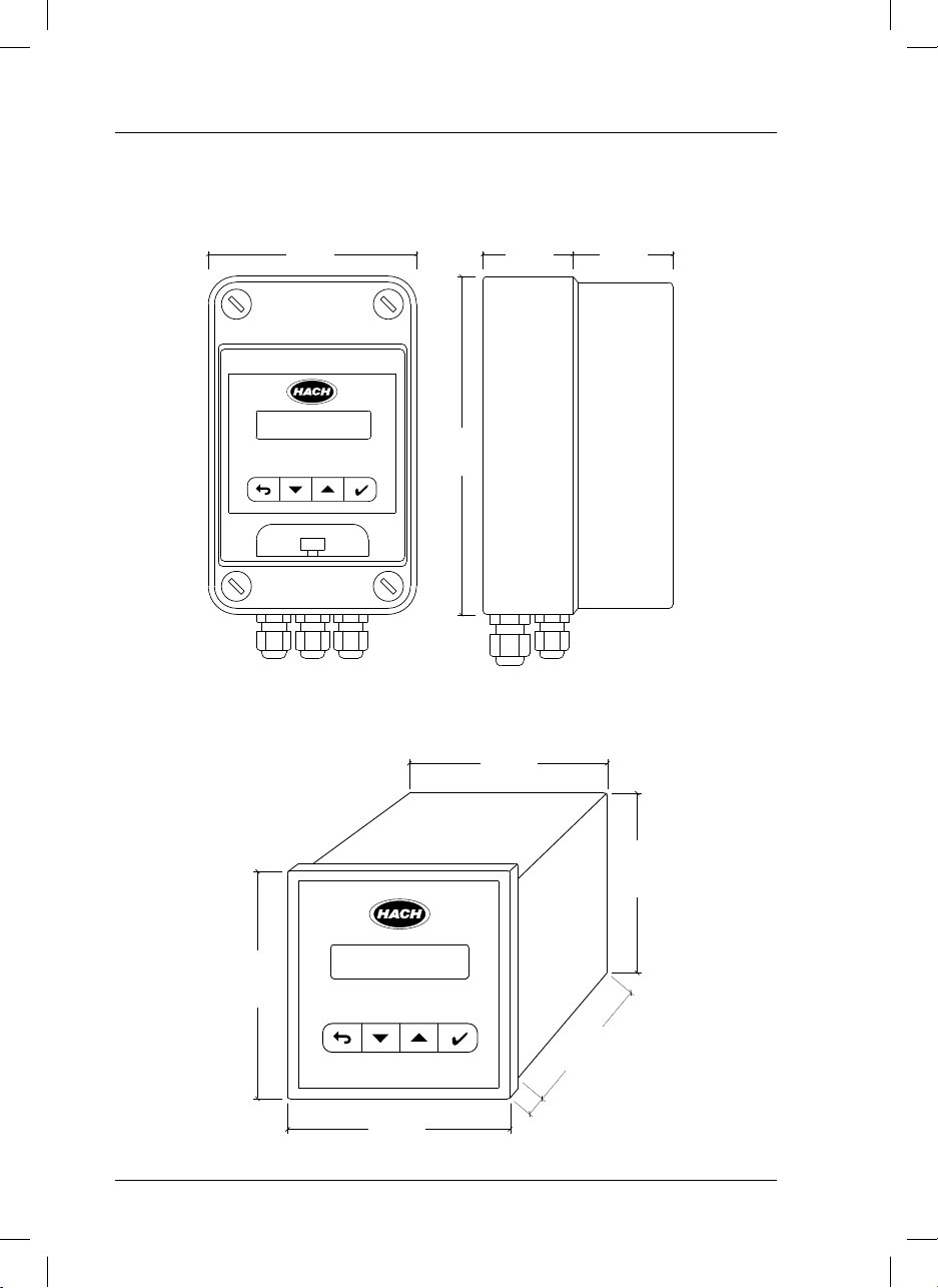
Dimensions
si629 C (wall mount):
105 x 170 x 100 mm (4 x 6.7 x 3.9 in.)
si629 C (panel mount):
96 x 96 x 100 mm (3.8 x 3.8 x 3.9 in.)
Warranty
Instruments: 2 years
Specifications are subject to change without notice.
ENGLISH
si629 C_HACH LANGE_Ed 0510.indd ANG:3si629 C_HACH LANGE_Ed 0510.indd ANG:3 20/5/10 12:06:4820/5/10 12:06:48

4
1. Technical Specifications
1.1. Dimensions
si629 C (wall mount)
si629 C (panel mount)
105 mm
4.1 in 45 mm
1.8 in 50 mm
2 in
170 mm
6.7 in
90 mm
3.5 in
96 mm
3.8 in
96 mm
3.8 in
90 mm
3.5 in
80 mm
3.1 in
7 mm
0.3 in
si629 C_HACH LANGE_Ed 0510.indd ANG:4si629 C_HACH LANGE_Ed 0510.indd ANG:4 20/5/10 12:06:4820/5/10 12:06:48

5
2. General information
As a result of constant improvements to our products sometimes differences may exist between this manual
and the instructions supplied with the instrument.
2.1. Safety information
Please, read carefully this information before installing and using the instrument !
Pay attention to all danger and caution statements.
ENGLISH
2.1.1. Use of hazard information
This symbol references the instruction manual for operation or safety information.
This symbol indicates that a risk of electrical shock or electrocution exists.
This symbol indicates the connection for Protective Earth.
This symbol indicates ground connection.
This symbol identifies a fuse.
Electrical equipment marked with this symbol may not be disposed of in European public disposal sys-
tems after 12 August of 2005. In conformity with European local and national regulations (EU Directive
2002/96/EC), European electrical equipment users must now return old or end-of life equipment to the
Producer for disposal at no charge to the user.
Note: For return for recycling, please contact the equipment producer or supplier for instructions on how
to return end-of-life equipment, producer-supplied electrical accessories, and all auxiliary items for proper
disposal.
DANGER
Indicates a potentially or imminently hazardous situation that, if not avoided, will result in death
or serious injury.
WARNING
Indicates a potentially or imminently hazardous situation that, if not avoided, may result in death
or serious injury.
CAUTION
Indicates a potentially hazardous situation that, if not avoided, may result in minor or moderate injury.
Important note
Indicates a situation that, if not avoided, could lead to damage to the instrument. Important infor-
mation that requires special emphasis.
Note
Information that supplements points in the main text.
Precautionary labels
Read carefully all labels and tags attached to the instrument.
si629 C_HACH LANGE_Ed 0510.indd ANG:5si629 C_HACH LANGE_Ed 0510.indd ANG:5 20/5/10 12:06:4820/5/10 12:06:48

6
2. General information
DANGER
si629 C (wall mount)
• Instrument (with strips for connections).
• User manual.
si629 C (panel mount)
• Instrument (with strips for connections).
• Clamps to fix to the panel.
• User manual.
2.3. Items supplied
• Remember that the voltage across accessible
parts of the open instrument, may be dangerous
to life. Do not open the instrument when it is
connected to the power supply, there are areas
whose voltage could cause death.
• Always disconnect power to the instrument
before it is opened.
• Repair or adjustment of an opened instrument
under voltage shall be carried out only by
a qualified technician who is aware of the
hazards involved.
• Never work in an environment subject to
explosion hazards. The housing of the
instrument is not gas tight.
• The Company will not be responsible for any
physical damage caused by non authorised
work or manipulation.
• It is the responsibility of whoever uses this
instrument to consult and establish appropriate
safety and health practices and determine the
applicability of regulatory limitations prior to use.
• Before connecting the instrument to a power
supply unit, make sure that the mains voltage
lies within the range:
230 or 24 V AC ±10%, 45-65 Hz (standard
version).
115 V AC ±10%, 45-65 Hz (under demand).
Important notes
• Read carefully the manual of the instrument.
• Avoid direct sunlight over the instrument.
• Exclude the following environmental influences:
- vibrations
- atmospheric humidity higher than 80 %
- corrosive gases present
- temperature < 0 °C, or > 50 °C (< 32 °F, or >
122 °F).
- powerful electric and magnetic fields.
• Only use original accessories and spare parts.
• Have the instrument serviced only by the
Company Service.
2.2. General product information
Proper use
The si629 C is used for conductivity, salinity and temperature measurement in food industry, waste water,
in the environment, etc.
si629 C_HACH LANGE_Ed 0510.indd ANG:6si629 C_HACH LANGE_Ed 0510.indd ANG:6 20/5/10 12:06:4920/5/10 12:06:49

7
3. Installation
ENGLISH
3.1. si629 C (wall mount)
DANGER
Only qualified personnel should conduct the tasks described in this section of the manual.
3.1.1. Assembly
Wall mounting
Open the case by unscrewing the 4 Ascrews.
For wall mounting of the instruments, use the Bdrill holes indicated on the scheme.
Pipe or column mounting
Use the pipe adaptor, PN LZU9120.99.
Install the pipe adaptor on the rear part of the instrument using both C drill
holes as indicated on the figure. Fit the unit with two clamps to the column.
C
C
Cable
tie
Rear view Pipe adaptor Instrument mounted
B
50 mm
2 in 50 mm
2 in
25 mm
1 in
25 mm
1 in
115 mm
4.5 in
A
Front view Side view Rear view
si629 C_HACH LANGE_Ed 0510.indd ANG:7si629 C_HACH LANGE_Ed 0510.indd ANG:7 20/5/10 12:06:4920/5/10 12:06:49

8
3. Installation
System functions
1,2 Voltage 230 or 24 VCA ± 10%.
(115 VCA upon request).
3 Ground connections, see Important
notes (page 9).
4,5 Current output 4-20 mA (EC).
6,7 Input for temperature probe.
8 Cell cable shielding
9 to 12 Entrada para célula de 2 polos.
13,14 Limit 1 relay contacts.
15,16 Alarm relay contacts.
17 to 19 Limit 2 or Cleaning relay contacts.
DANGER
Always disconnect power to the instrument when making any electrical connections.
3.1.2. Connections
When making any wiring connections to the instrument, any warnings and notes found throughout the
manual must be adhered to. For more safety information see “Safety information” on page 5.
Details
To open the transparent front door, press with two
fingers the part marked with ( ) in the scheme.
Cable glands.
On the lower part of the instrument there are 5
cable glands, 2 PG 7 and 3 PG 9.
PG 9 (3 units)
PG 7 (2 units)
DANGER
High-voltage wiring for the instrument is protected by a protective casing. The protective casing
must remain in place unless a qualified installation technician is installing wiring for power.
si629 C_HACH LANGE_Ed 0510.indd ANG:8si629 C_HACH LANGE_Ed 0510.indd ANG:8 20/5/10 12:06:5020/5/10 12:06:50

9
3. Installation
ENGLISH
Terminal assignment (interior panel)
Important notes:
• El si629 C does not require ground conec-
tion (3 or 4 terminals).
• In environnements with interference prob-
lems it is recommended to connect the in-
strument to ground in terminal 3.
If ground connection is not available, it is
recommended to leave terminal 3 free and
connect the additional shield of the triaxial
cable to the terminal 8 (Pt 1000 shielding).
L 1
A
L 2 / C
4-20 mA
CELL
VCA
Pt 1000
WHEN IT IS ON, IT INDICATES A FUSED FUSE.
DANGER
Relays:
- Limit the current up to 3 A by using one fuse.
- Do not connect cables with voltage higher than 24 V.
si629 C_HACH LANGE_Ed 0510.indd ANG:9si629 C_HACH LANGE_Ed 0510.indd ANG:9 20/5/10 12:06:5020/5/10 12:06:50

10
3. Installation
Plug-in screw connector Clamp to fix to the panel
Side view
3.2. si629 C (panel mount)
DANGER
Only qualified personnel should conduct the tasks described in this section of the manual.
3.2.1. Assembly
For the si629 C mounting a drill hole is required according to the diagram.
After putting the instrument in the panel, it must be fitted using two clamps as indicated in the figure.
92 mm
3.7 in
92 mm
3.7 in
80 mm
3.1 in
21 mm
0.8 in 7 mm
0.3 in
Panel
Drill hole
si629 C_HACH LANGE_Ed 0510.indd ANG:10si629 C_HACH LANGE_Ed 0510.indd ANG:10 20/5/10 12:06:5120/5/10 12:06:51

11
3. Installation
ENGLISH
When making any wiring connections to the instrument, any warnings and notes found throughout the
manual must be adhered to. For more safety information see “Safety information” on page 5.
3.2.2. Connections
System functions
DANGER
Always disconnect power to the instrument when making any electrical connections.
1 Ground connection, see Important
notes (page 12).
2,3 Power supply 230 or 24 VCA ± 10%.
(115 VCA upon request).
4,5 Alarm relay contacts.
6,7 Limit 1 relay contacts.
8,9 Limit 2 or Cleaning relay contacts.
10,11 Current output 4-20 mA (EC).
12 to 15 Input for 2 pole cell.
16 Cell cable shielding.
17,18 Input for temperature probe.
DANGER
High-voltage wiring for the instrument is protected by a protective casing. The protective casing
must remain in place unless a qualified installation technician is installing wiring for power.
si629 C_HACH LANGE_Ed 0510.indd ANG:11si629 C_HACH LANGE_Ed 0510.indd ANG:11 20/5/10 12:06:5120/5/10 12:06:51

12
3. Installation
Important notes:
• El si629 C does not require ground
connection (terminal 1).
• In environnements with interference problems
it is recommended to connect the instrument to
ground using terminal 1.
It is also recommended to use shield cables
for the cell signal (triaxial cable), and the
temperature probe.
The external shield of the triaxial cable and
the temperature cable must be connected to
terminal 16.
DANGER
Relays:
- Limit the current up to 3 A by using
one fuse.
- Do not connect cables with voltage
higher than 24 V.
Terminal assignment (rear panel)
Transmitter si629 C
RED
VCA
A
L 2 / C
L
CELL4-20 mA
S/N:
CRISON INSTRUMENTS, S.A.
E-08328 ALELLA - Barcelona
Made in Spain
IP 54
3.3. Cell cables
Compensation of the cable length
To minimize the effect of the cable resistance in a conductivity measurement, the cable length is compensa-
ted by the 4-wire system. With the Pt 1000 temperature sensor, the cable resistance has little importance.
However, in order to reduce the resistance of the conductor to a half, 2 cables have been connected to
the ends of the sensor.
3.3.1. Cells with MP-5 connector
TERMINALS COLOUR
si629 C
(wall mount) si629 C
(panel mount)
618White
618Brown
717Pink
7 17 Yellow
816Shield
915Green
10 14 Blue
11 13 Gray
12 12 Red
MP-5 connector, 5 contacts
si629 C_HACH LANGE_Ed 0510.indd ANG:12si629 C_HACH LANGE_Ed 0510.indd ANG:12 20/5/10 12:06:5120/5/10 12:06:51

13
3. Installation
ENGLISH
Important note:
Fit a jumper between terminals 9 and 10 (12 and 13 in panel mount instrument) and another between
the terminals 11 and 12 (14 and 15 in panel mount instrument).
3.3.2. Cells with connector S8
3.4. Protective wiring of switching contacts
Relay contacts are subjected to electrical erosion.
Especially with inductive and capacitive loads, the service life of the contacts will be reduced.
For suppression of sparks and arcing, components such as RC combinations, nonlinear resistors, series
resistors and diodes should be used.
Typical protective wirings
AC applications with inductive load DC applications with
inductive load AC/DC with
capacitive load
Load
Contact
relay
Diode
1N4007
Typical RC at 230 VAC: Capacitor 0.1 µF/630 V
Resistor 100 Ω/1 W
RC
RC R
Load
R, for example:
5 Ω/ 1 W at
24 V / 0.4 A
Maximum relays load: AC < 24 V / < 3 A / < 72 VA.
TERMINALS COLOUR
si629 C
(wall mount) si629 C
(panel mount)
9 12 Middle
10 13 Middle
11 14 Shield
12 15 Shield
si629 C_HACH LANGE_Ed 0510.indd ANG:13si629 C_HACH LANGE_Ed 0510.indd ANG:13 20/5/10 12:06:5120/5/10 12:06:51

14
4. Operation
4.1. Description
Display
si629 C have an alphanumeric display that explains itself. One of the most significant screens is des-
cribed below as an example:
Sample temperature
Resolution:
1 °C manual selection.
0.1 °C measuring with Pt 1000
Measured value.
MEASURING 21.3 °C
10.9µS/cm @ 25 °C
Measuring units.
Keys
ENTER.
• Horizontal movements to move forward in the “diagram”.
• Acceptance of numerical values.
ESCAPE.
• Horizontal movements to move back in the “diagram”.
• Vertical movements to move back in the “diagram”.
• To erase numerical values.
• Modification of numerical values.
• Cursor “>” movements on the screen.
Reference temperature
25 or 20 °C
si629 C_HACH LANGE_Ed 0510.indd ANG:14si629 C_HACH LANGE_Ed 0510.indd ANG:14 20/5/10 12:06:5220/5/10 12:06:52

15
ENGLISH
4. Operation
4.2. Setting up
Connect the si629 C to mains. At power up the first time only the following screens will appear:
The instrument is already measuring conductivity, with the following factory settings:
• Temperature coefficient 2% / °C.
• Cell constant C=1 cm-1.
• Reference temperature, RT, at 25°C.
• Relay 1, limit activated at 1000 µS/cm, and deactivated at 800 µS/cm (measuring salinity, activated
at 1 mg/l and deactivated at 0.8 mg/l).
• Relay 2, cleaning during 3 sec each hour, with 5 sec of post-cleaning time.
• Alarm relay, activation after 10 min of reading out of limits.
• Current output 4 mA = 200 µS/cm, 20 mA = 2000 µS/cm (measuring salinity
4 mA = 0.2 mg/l, 20 mA = 2 mg/l).
• Current output with the instrument in “Hold” mode, 21mA.
• Data Logger deactivated.
To modify this configuration see page 17.
si629_C
V1.0
Français
English
Deutsch
Português
IDIOMA >Español
Italiano
MEASURE MEASURING 22.3°C
545 µS/cm @25°
Possibility to select other
language with keys.
si629 C_HACH LANGE_Ed 0510.indd ANG:15si629 C_HACH LANGE_Ed 0510.indd ANG:15 20/5/10 12:06:5320/5/10 12:06:53

16
4. Operation
4.3. Quick guide
This page shows the instrument’s operation by blocks. It is intended to provide a quick idea about all the
instrument’s capabilities and how to gain access to them.
Security acces
code.
It limits the access
to calibration
or programming
of the instrument
by non authorised
personnel.
When the “Code” screen has been shown
for more than 30 sec. the instrument will
automatically return to MEASURE.
MEASURING 22.3°C
545 µS/cm @25°
CODE 000
Vary the underlined digit with
and accept with .
Authorised code = 100
Instrument in “Hold” state
When being in the gray zone, the instru-
ment is in hold state:
• Limit and cleaning relays are open.
(Alarm OFF).
• According to the configuration the cu-
rrent output is frozen at 21 mA or at the
mA corresponding to the last measured
value.
(*) When being in Test 4-20 the current is
the one programmed manually to be able
to carry out the test.
To quit the hold state it is necessary to re-
turn to Measure. The Current output 4-20
and the Relays will activate in 10 sec.
MEASURE
CALIBRATE
CELL
CONFIGURATION
ALARM
OUTPUT 4 to 20 mA
TEST 4 to 20 mA
DATA LOGGER
See “Configuration“
(page 17)
See “Programming ...”
(page 20-21)
MANUAL RELAY
LANGUAGE
LIMITS
CLEANING
HOLD
See “Calibration“
(page 18)
See “Test 4-20 mA“
(page 24) (*)
See “Manual control
of relays
(page 24)
See “Data logger““
(page 25) (*)
si629 C_HACH LANGE_Ed 0510.indd ANG:16si629 C_HACH LANGE_Ed 0510.indd ANG:16 20/5/10 12:06:5320/5/10 12:06:53
Table of contents
Languages:
Other HACH LANGE Transmitter manuals
Popular Transmitter manuals by other brands

Sennheiser
Sennheiser SK 5212-II - FREQUENCY TABLES instruction manual

Emerson
Emerson Rosemount 248 quick start guide

Oxygen
Oxygen 3-8-1000-0 manual

ImpulseRadar
ImpulseRadar Raptor 45-Tx user manual

NIVELCO
NIVELCO NIVOPRESS DT Series Installation and programming manual

Jung
Jung BLE 2990-L Series operating instructions