taranis Q X7 User manual

Programming the Taranis Q X7 Transmitter for Combat Robotics
The Taranis Q-X7 with OpenTX 2.2 firmware is a remarkably flexible transmitter that can adapt
to very sophisticated control requirements. Unfortunately, all that flexibility comes with a
complex user interface that confuses novices and gives experienced R/C jockeys a bewildering
range of choices. For example: you can’t simply turn on Elevon mixing – you need to build up a
channel mix from the elements available to the transmitter. This takes some thought and
planning.
While there is ample documentation available on the web to explain in detail the theory and
practice of OpenTX, two things led me to write this guide:
1. OpenTX was not developed for combat robots. The available tips and examples are
typically designed for servo-driven mechanical aircraft control surfaces that have
different considerations than do the Electronic Speed Controllers used in robot drive
trains.
2. The basic requirements of setting up a robot drive train and typical weapon control are
relatively simple compared to the capabilities of OpenTX. A robot builder shouldn’t be
forced learn the full scope of the firmware capability simply to get their robot operational.
This guide will skip over the bulk of the theory and provide examples of set-up, tuning, and
troubleshooting for standard combat robot layouts. Once you have your ‘bot operational you can
take time go as deep into control theory as you like.

Physical Setup
There are multiple on-line tutorials that cover the process of un-boxing, hardware adjustment,
preference selection, menu navigation, receiver binding, failsafe setting, and range testing.
Since this is all the same for aircraft or robot I’m not going to duplicate that info here, but I will
assume that you have your transmitter operational and have figured out the menu navigation
controls. If you need some help with that process, try this tutorial:
RCdiy Taranis Q X7 OpenTX –Setup
http://rcdiy.ca/taranis-q-x7-tutorial-first-flight-setup/
As delivered, the Taranis Q-X7 defaults to the ‘Mode 2’ stick layout with channels one thru four
assigned to Aileron, Elevator, Throttle, and Rudder (AETR) in that order. This stick and
channel layout can be changed, but the examples in this guide assume that this default channel
layout is your starting point.
Menu Navigation
The action all takes place in the Model Setup menu. Power on and dismiss any warning
messages to get to your home screen:

A quick tap on the MENU button (≡) will take you to the Model Setup menu. If you hold it too
long you go to the Radio Setup menu -- just a tap. Now tap the PAGE button repeatedly to flip
down thru the screens. A long press on the PAGE button will move you up a screen. Almost all
of our robot setup will be done on three screens: INPUTS, MIXER, and OUTPUTS.
In this guide we will use these three screens to set-up the following common combat robot
functions:
As a bonus I’ll toss in a feature from a fourth model setup screen that will allow you to command
servo motion up to 150% of normal range. Let’s get to work.
The Mixer Screen -- Linking Inputs to Outputs
The mixer screen accepts input signals -- from the transmitter sticks, switches, and knobs -- and
assigns them to output channels that will be sent to the receiver. Multiple inputs may be
assigned to individual outputs to create channel ‘mixes’, and the signals may come direct from
the inputs or after they have been modified by the INPUTS screen.
Constructing a Single Stick Drive Mix
With conventional transmitter firmware it’s a simple matter to establish single-stick control of
throttle and steering -- just go to the mix menu and turn on ‘Elevon’. With OpenTX firmware
there are no pre-defined mixes you can just turn on – you must define your own mixes.
To properly control motion in a skid-steer robot we require the left and right motors to respond to
the Elevator stick axis (right stick up/down) by spinning in opposite directions (one clockwise,
one counterclockwise) to move the robot forward and back, and we need the left and right
motors to respond to the Aileron stick axis (right stick left/right) input by spinning in the same
direction (both clockwise or both counterclockwise) to rotate the robot right or left. We’ll set up
CH1 to control the left side motor controller and CH2 to control the right side.
Page down thru the Model Setup menu to the MIXER screen. With default settings (Mode 2,
AETR) your mixer screen should look like this:
1.
A single
-
stick throttle and steering mix.
2. Assign an output channel to a toggle switch.
3. Create a steering sensitivity dual-rate switch.
4. Program a switch to correct stick response on an inverted robot.
5. Limit servo motion range to prevent lifter stall.
6. Reverse the response of individual receiver outputs.

Your MIXER screen now looks like this:
CH2
responds to Elevator input by default. We will insert an additional line in the
CH2 mix to add Aileron response in the direction opposite to CH1. On the MIXER
screen:
Use the scroll wheel to highlight the CH2 line, and long-press the ENTER
button to bring up an action menu.
Tap ENTER to enter the EDIT menu.
Scroll down to Weight, tap ENTER, scroll the value down to -100.
Tap ENTER, tap EXIT twice.
Long-press the ENTER button to bring up an action menu.
Scroll down to Insert Before and tap ENTER to bring up a new menu.
Scroll down to Source, tap ENTER, scroll to Ail.
Tap ENTER, tap EXIT twice.
CH1
responds to Aileron input by default. We will insert an additional line in the
CH1
mix to add Elevator response. On the MIXER screen:
Use the scroll wheel to highlight the CH1 line, then long-press the ENTER
button to bring up an action menu.
Scroll down to Insert After and tap ENTER to bring up a new menu.
Scroll down to Source, tap ENTER, scroll to Ele, tap ENTER, tap EXIT twice.

Your MIXER screen now looks like this:
There may be some clean-up to the response directions based on motor polarity that we’ll sort
out in the troubleshooting section, but that’s our mix.
Assigning an Output Channel to a Switch
Sometimes you don’t need the range and precision of a control stick to activate an output
channel. Maybe you’re just activating an RC switch to fire a flipper mechanism. A transmitter
switch would serve that purpose nicely – let’s assign one to output CH5:
Your MIXER screen now looks like this:
CH5
is unassigned. We will assign it to respond to the momentary toggle switch
SH
.
On the MIXER screen:
Scroll to highlight the CH5 line, then tap ENTER.
Scroll down to Source, tap ENTER, scroll to SH.
Tap ENTER, tap EXIT twice.
N
OTE
:
For aircraft applications, an Elevon mix will typically ‘Weight’ the mix
elements at ‘50’ rather than ‘100’ to prevent ‘clipping’ the motion of the servos used
to move their fight control surfaces. That isn’t an issue with robot control, plus we
need to assure that the electronic speed controllers provide full forward and reverse
throttle in response to Elevator input. The ‘100’ weight on Aileron gives more steering
response than most drivers like, but we will take care of that in the INPUTS screen.

You could assign any unused switch to control CH5 -- but SH is a momentary switch, spring-
loaded to return to its default state when released. That makes it perfect for triggering a flipper.
The INPUTS Screen -- Adjusting Control Response
Time to do some work on the INPUTS screen where we have the option to modify the signal
coming from a stick, switch, or knob before it gets to the MIXER screen. We can modify
response ‘weight’, add switches to select between weight options, and even reverse the
direction of input response.
Adjusting Steering Responsiveness
Page down thru the Model Setup menu to the INPUTS screen. With default settings your inputs
screen should look like this:
Your INPUTS screen now looks like this:
As mentioned in the
MIXER
section, a
100
Weight assigned to the aileron input gives
too much steering responsiveness for most drivers. The INPUTS screen is the place
to adjust that weight. On the INPUTS screen:
Use the scroll wheel to highlight the Ail line, then long-press the ENTER
button to bring up an action menu.
Tap ENTER to enter the EDIT screen.
Scroll down to Weight, tap ENTER, scroll down to 50.
Tap ENTER, tap EXIT twice.

Adjustments to the Weight of the Aileron stick here will affect all uses of the Aileron input in the
MIXING screen. It’s easier to have only one place to make adjustments to steering sensitivity.
Adding a Dual Rate Switch
We’ve reduced steering response to a more comfortable level, but there are times when it would
be useful to quickly restore full rotation speed -- maybe for a simple victory dance, or maybe to
spin fast enough to flip back upright when inverted. Let's assign a switch to handle that job:
Your INPUTS screen now looks like this:
Assigning a switch to select between two control rates – a ‘Dual Rate’ switch. On the
INPUTS screen:
Highlight the Ail line, then long-press the ENTER button to bring up an action
menu.
Tap ENTER to enter the Edit screen.
Scroll down to Switch, tap ENTER, flip switch SA down then back up, tap
enter, tap EXIT twice.
Long-press the ENTER button again.
Scroll to Insert After and tap ENTER.
Tap EXIT twice.

A Simple Invert Switch
So far everything we’ve done in OpenTX has been a little more difficult than it would have been
on a conventional menu-driven transmitter. You’re probably wondering why anyone bothered to
write transmitter firmware that makes things more difficult. It’s not quite like that – Open TX does
make simple things a little more difficult, but it can make complicated things a lot simpler. Here’s
an example.
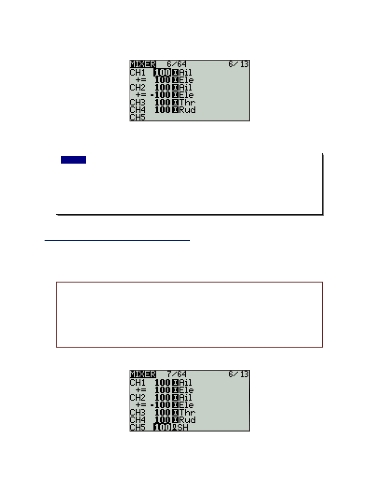
When a wheeled robot is inverted the steering remains correct, but the throttle
direction is reversed. Assigning a switch to reverse the response of the Elevator stick
axis in a conventional transmitter is complex, but in OpenTX it’s simple. On the
INPUTS screen:
Use the scroll wheel to highlight the Ele line, then long-press the ENTER
button to bring up an action menu.
Tap ENTER to enter the Edit screen.
Scroll down to Switch, tap ENTER, flip switch SF down then back up.
Tap enter, tap EXIT twice.
Long-press the ENTER button again.
Scroll to Insert After and tap ENTER.
Scroll down to Weight, tap ENTER, scroll the value down to -100.
Tap enter, tap EXIT twice.
How
does this
work
?
If there are multiple lines entered under a single input, the
transmitter evaluates the first line to see if any conditions it includes are met. If they
are, that line is used. If not, it skips down a line and repeats the evaluation process.
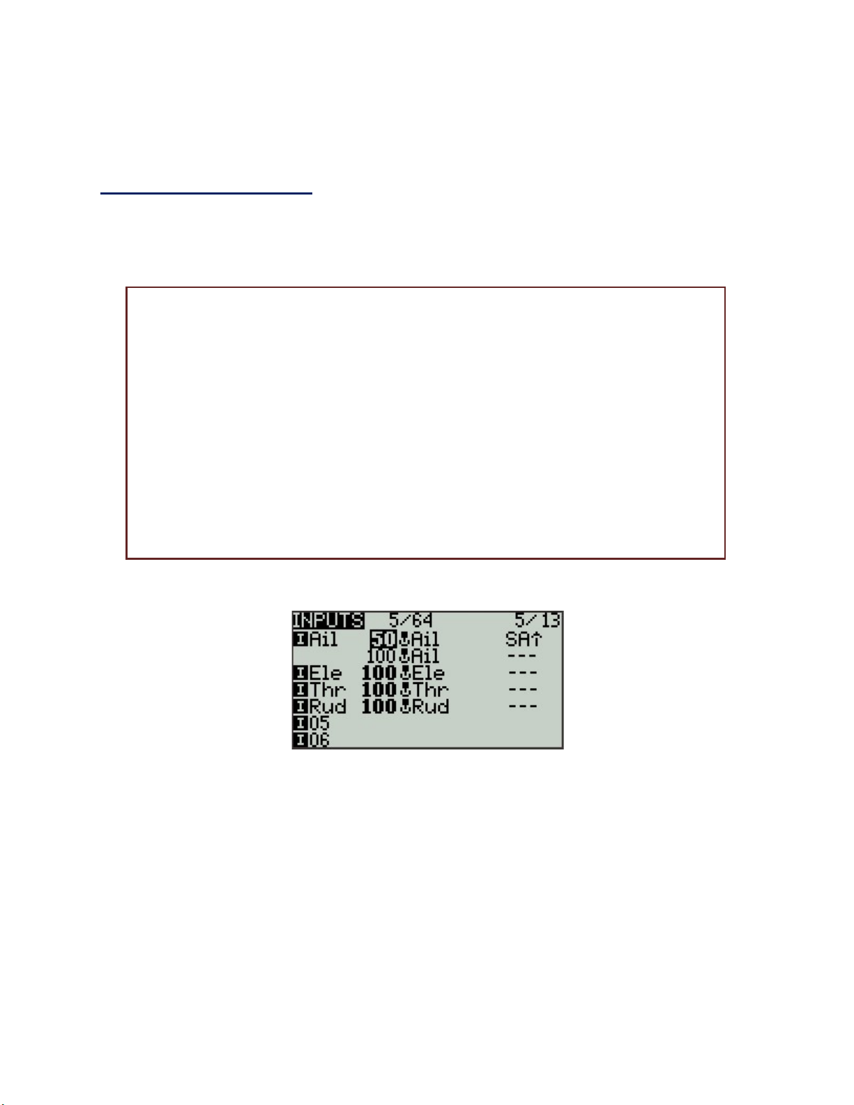
Our first Aileron line has the condition SA⇑ that requires that switch SA be
in the up position – the position the transmitter expects at start-up. If switch
SA is up the line will be accepted and the steering rate will be a controllable
50.
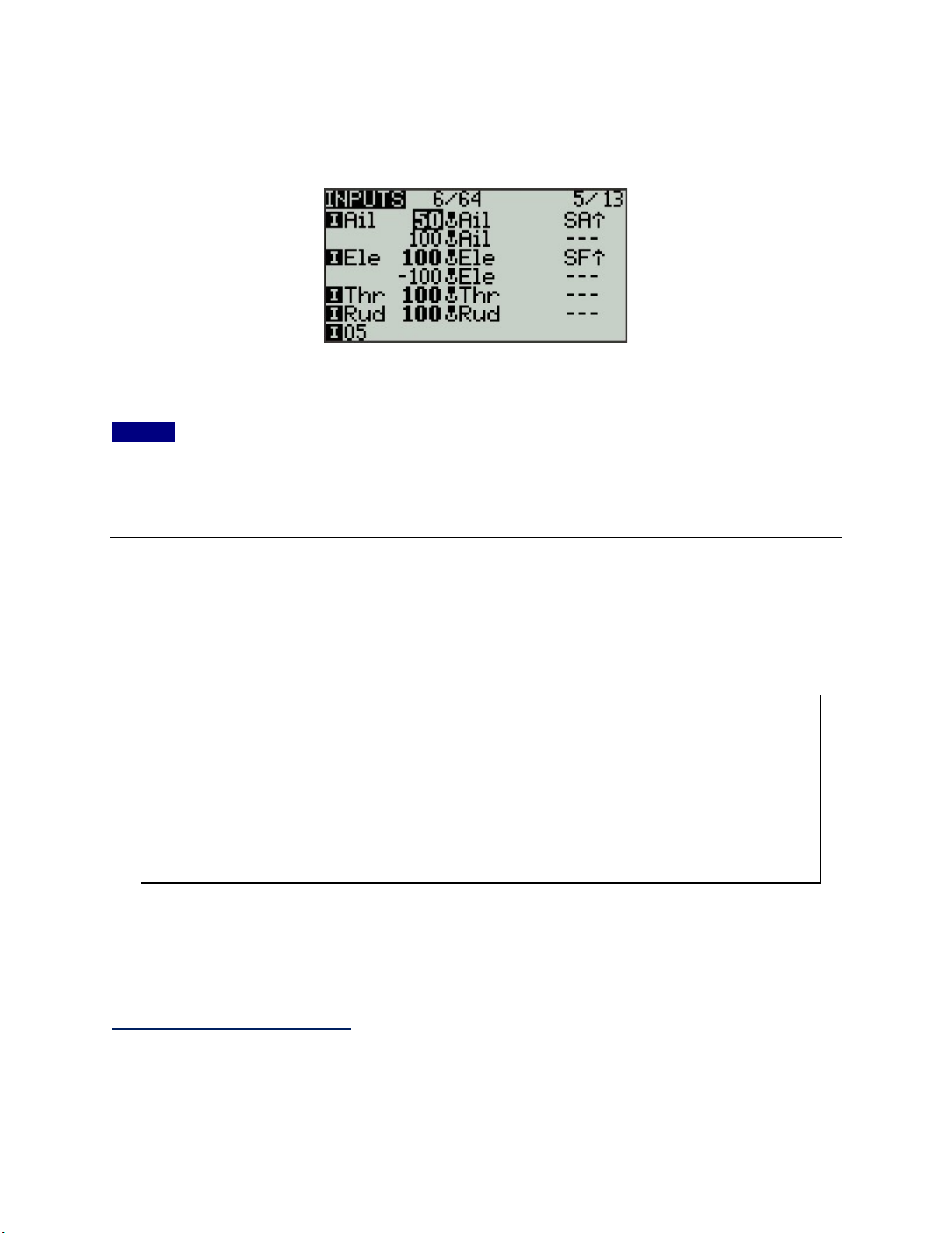
If switch SA is not up, the transmitter will skip down to the second line to
evaluate its condintion. Ths second line has no condition set, so it will be
accepted and the steering rate will be a very quick 100.
You can choose different values for the Weight to suit your driving preference --
and you can choose a different switch. Yes, you can add more lines for additional
conditions, but leave the last line with no conditions.

Your INPUTS screen now looks like this:
When Switch SF is up (SF⇑) the elevator response is normal, but when SF is not up the throttle
response is reversed. You can of course choose a different switch to suit your preferences.
NOTE: Aircraft users program a different type of invert switch because this simple approach
does not invert the axis trim setting. Trims are important if you’re controlling servos, but robot
motor controllers seldom rely on trims to adjust their center position. This approach should work
just fine for your robot. If not, look up the aircraft version on the ‘net.
The OUTPUTS Screen -- Limiting and Reversing
I’ve arranged the topics in this guide to mirror the order of progression a robot builder might
follow in setting up a Taranis Q X7 for their use. At this point it would be helpful to follow a
position signal all the way thru the transmitter to better understand the ‘big picture’.
So, the OUTPUTS screen is the last stop before the signal is transmitted to the receiver. Any
adjustments made here will modify the output port assigned on the MIXER screen by adjusting
the magnitude and direction of the signal that will arrive at the receiver port.
Limiting Motion on a Servo
Suppose you have a servo powered 4-bar lifter in your antweight that’s controlled by the
‘Throttle’ stick axis on CH3. This particular mechanism does not require the full range of servo
motion to drive the lifter – the lifter is completely retracted at -75% of servo motion and is fully
A position signal is generated by a stick axis, switch, or knob.
That signal may be routed to the INPUTS screen for modification before being
passed to the mixer.
Signals coming into the MIXER screen may be combined with other before being
assigned to a receiver output port.
The OUTPUTS screen allows final modification to the direction and magnitude of
the combined signals from the mixer before they are transmitted to the receiver.

extended at +90% servo motion. The servo will ‘stall’ if commanded outside this range, and
stalling is hard on a servo. We can limit the range that CH3 can command to prevent servo stall.
Page down thru the Model Setup menu to the OUTPUTS screen. With default settings your
outputs screen should look like this:
Your OUTPUTS screen now looks like this:
Full upward throw on the Throttle stick axis will now provide only 90% of full upward servo
motion, and full downward throw will provide only 75% of downward servo motion. No servo
stall!
The
OUTPUTS
screen allows direct limiting of the motion range commanded on
each side of the motion center point. Here we will limit servo motion to 75% of
normal below the center point and 90% above.
Use the scroll wheel to highlight the CH3 line, then tap the ENTER button to
bring up an action menu.
Tap ENTER to enter the EDIT screen.
Scroll down to the Min line, tap ENTER, scroll to -75.0 and tap ENTER.
Scroll down to the Max line, tap ENTER, scroll to 90.0 and tap ENTER.
Tap EXIT twice.

Bonus Content By default OpenTX prevents assigning Output travel values outside the range
of -100 to 100. However, most servos are capable of responding to signals outside this range to
provide an extended range of motion. If you require increased extension from a servo you can
over-ride the default limits on the Model SETUP screen:
You may now enter ‘Min’ and ‘Max’ values on the OUTPUTS screen over an extended range
from -150 to 150. Most servos will not go all the way to 150% of normal range, so use caution in
exploring motion limits. And no, extended range will not make your drive motors faster – don’t
even try.
Channel Reversing
We setup the single-stick drive mix on the MIXER screen to provide the correct signals to the
drive motor controllers, but we may need to reverse the direction of the signal provided at one or
both of the receiver ports that command the motor controllers to compensate for motor polarity.
Similarly, the action of a servo powered lifter or the response of a channel assigned to a toggle
switch may also require adjustment in the signal direction at the receiver port.
In a conventional transmitter there would be a menu to deal with ‘Servo Reversing’ to sort out
these issues. In OpenTX the same function is folded into the Outputs screen.
We can reverse the direction of operation of mixed or unmixed outputs on the
OUTPUTS screen by ‘inverting’ a specific channel. In this example we invert the
output of CH2:
Use the scroll wheel to highlight the CH line, then tap the ENTER button to
bring up an action menu.
Tap ENTER to enter the EDIT screen.
Scroll down to the Direction line, then tap ENTER to change the mode to
INV.
Tap EXIT twice.
Page upward from the
OUTPUTS
screen multiple times to find the
SETUP
screen.
An option box here will allow will enable entry of extended allows direct limiting of the
motion range commanded on each side of the motion center point. On the SETUP
screen:
Scroll down – it’s pretty far - to the E.Limits line.
Tap ENTER to check the E.Limits box.
Tap EXIT.

Your OUTPUTS screen now looks like this:
The change to the screen is subtle: the little arrow to the right of the ‘100’ on the CH2 line now
points to the left instead of the right, indicating in ‘inverted’ response.
In the next section we will check the operation of the ‘Elevon’ mix to see if and where we may
need to invert output channels to obtain correct response to our stick inputs.
Troubleshooting the Drive Mix
Find a safe place to test the robot drive, unplug all weaponry, and power up the radio and robot.
Try a little gentle forward motion and a slow turn to the right.
Given a forward command, only one motor responds
--
given a right turn
command, only the other motor responds.
You have both transmitter mixing and on-board mixing on the
controller turned on. Turn off the on-board controller mixing.
Given a forward command, robot backs up straight.
Invert the response for both of the motor control channels: CH1 and
CH2.
Given a forward command, robot spins in place.
Invert the response for the channel that feeds the controller for the
motor that is backing up.
Given a right turn command, the robot turns left.
You have the left and right motor controllers plugged into each other’s
receiver ports. Unplug the controller connectors from the receiver and
plug the connector that was in CH1 into CH2 and vice versa. You may
have to invert response for one or both channels to get correct
forward/reverse motion, but the turning control will be correct when
you're done.

Summary and Additional Resources
There you have it. We’ve only scratched the surface of what OpenTX can do, but the examples
given here will suffice to get all but the most exotic combat robots up and running. Now that
you’ve got a taste of how the firmware works you have a good base for implementing less
common functions and features, like:
Triple rates
Voice prompts
Logical switches
Exponential curves
What those knobs can do
And even a four-channel omnidirectional Mecanum drive mix!
Here are some resources to get you started:
OpenTX University - http://open-txu.org/
OpenTX Online Manual - http://rcdiy.ca
OpenTX Clinic - https://rc-soar.com/opentx/basics/index.htm
Copyright 2020, Mark Joerger – Team Run Amok
Table of contents
Popular Transmitter manuals by other brands

Qianjin Electronic
Qianjin Electronic OT86-4F user manual

SABINE
SABINE SW70-T Quick setup guide

Listen
Listen lt-800 user guide

TellSystem Communication
TellSystem Communication ProCon GSM Installation and user guide

Sundrax
Sundrax RadioGate Solid RGS-X-DB-AC user manual

Novus
Novus TxBlock-USB operating manual