Form OME-054 06/2006 ©2006 Omega National Products
I M P O R T A N T
INSTALLATION INSTRUCTIONS FOR
OMEGA NATIONAL PRODUCTS
SELECT SERIES RANGE HOOD AND LINER
Before installation may begin, the following components are required:
· Fan unit, part number RHVBF10WH or
Blower unit, part number RHVBB20WH
• Ducting System • Metal Liner • Decorative Wood Hood
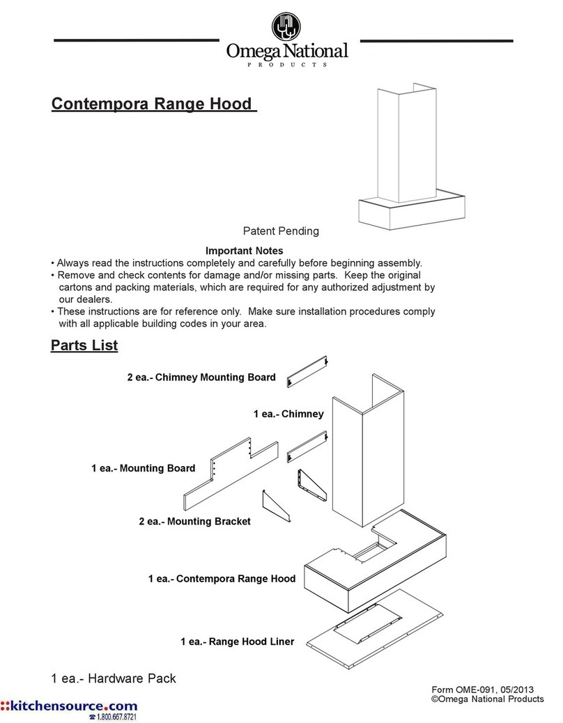
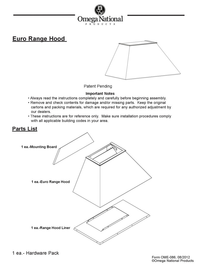
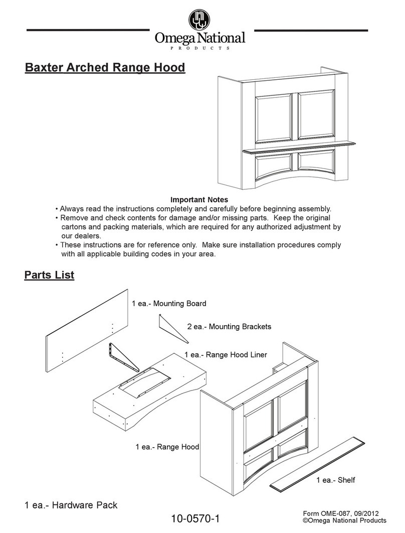
A. The Wood Hood is composed of two separate components:
1. The decorative Hood Front, Figure 1
2. T-shaped Metal Liner, Figure 2
NOTE: T-shaped liner shipped with unit as standard.
3. The ventilation system (power module and ducting system) is not
included and must be purchased separately.
B. Installation: Metal Liner – T-Shaped, Figure 3
1. Measure up 6 1/8” from the bottom of adjacent cabinets. Scribe a level
line horizontally across depth of both cabinets.
2. Raise Metal Liner so that bottom edge of liner is level with scribed lines.
Use four (4) #8 x 1/2” screws (provided) to attach liner to adjacent
cabinets through pre-drilled holes in liner. (If metal liner is not flush to
cabinet sidewalls, it may be necessary to use a filler piece to avoid
bowing the liner.) Locate studs and place two #8 x 1 1/4” (supplied)
through rear of liner.
C. Installation of Omega National Products Select Series Wood Hood
1. Slide decorative hood front into position over T-Shaped liner and
between adjacent cabinets. Install the hood front by joining to adjacent
cabinets through the front frames using (4) #8 x 2 1/2” screws (not
provided).
D. Installation of Power Units
RHVBF10WH Fan Unit – see installation instructions enclosed with each
Power Unit.
RHVBB20WH Blower Unit - see installation instructions enclosed with each
Power Unit.
Source for all parts listed:
Your local distributor or: Omega National Products
1010 Rowe Street, Elkhart, IN 46516
574-295-5353 ▪574-295-5329(fax)
Figure 1
Figure 2
Figure 3
30" or 36"
16 1/2"
4"
10 1/4" X 19 1/2"
OPENING
30" or 36"


