Omega OMEGA+ User manual

OMEGA+OMEGA+
TRANSCEIVER QRP
PORTABLE RADIO
INSTRUCTION MANUAL
www.omega-radio.eu

1
SPECIFICATION
Frequency coverage (MHz)
RX: 0.100 - 30.000
TX:
1.800 - 2.000
3.500 - 3.800
5.100 - 5.500
7.000 - 7.200
10.100 - 10.150
14.000 - 14.350
18.069 - 18.168
21.000 - 21.450
24.890 - 24.990
28.000 - 30.000
Mode: USB / LSB / CWU / CWL
Antenna conector: SO-239
Power supply requirement: 11-14V DC
Power consumption: Tx max power: 1,6A; Rx 0,26A
Dimensions ( WxHxD): 120x40x180 mm
Weight ( approx): 800g
Temp. range: -10°C to +50°C
Output power: >5W
Sensivity: 0.16µV
AF output power: 0,7W with an 8Ù load
Ground: negative ground
Supplied accesories: hand microphone, DC power cable
Available models:
Monobander ( any band)
10 bands ( all HF bands)

press and hold to select either VFO A or VFO B
A/B
LOCK press and hold to lock all buttons and vfo knob
MODE press to select LSB, USB, CWL or CWU mode
FIL press to turn the audio narrow filter ON or OFF
ATT press and hold to turn the -20dB receiver attenuator ON or OFF. Using
this option is recommended on low frequency band (160m/80m/60m/40m)
RIT
14.073.00
ATT
14.073.00
+01.50
RIT
press to turn the RIT (Receive Incremental Tuning) function ON or OFF
14.073.00
FIL
14.073.00
USB
14.073.00
LOCK
14.073.00
VFO A
press to select frequency band up
press to select frequency band down
14.073.00
STEP
14.073.00 press to select 10Hz, 100Hz, 1kHz or 10kHz tuning step
SPLIT
14.073.00
14.093.00
press and hold to enter split-frequency operation, allowing you to use
different transmission and reception frequencies
14.073.00
MODE RIT STEP
FIL ATT SPLIT
A/B
LOCK
SETUP
13,8V
band 20m LSB
S0
RX
band 20m
FRONT PANEL
VFO
VOLUME
2

3
SETUP
to enter SETUP press simultaneously and buttons
and hold 3 seconds.
In SETUP mode: to select option turn vfo knob, to enter option
press and hold , to save changes press and hold .
1. EXIT SETUP – enter to exit setup
a. Return setup
b. Exit setup – exit without saving changes
c. Save and exit – save changes and exit
2. Si XTAL MODE – enter to select quartz resonator type
a. 25MHz / 8pF
b. 25MHz / 10pF
c. 27MHz / 8pF
d. 27MHz / 10pF
3. Si I2C adr. – enter to select I2C address
a. 0x60h
b. 0x62h
4. Si correct. – enter to set frequency correction [Hz]
5. BFO USB freq – enter to set BFO USB frequency
6. BFO LSB freq – enter to set BFO LSB frequency
7. CW release – enter to set CW relay release time [ms]
8. CW speed – enter to set CW speed
9. CW shift – enter to set shift in CW mode [Hz]
10. Band COUNTIN – enter to turn the band countinuous mode ON or OFF
11. Band 160m – enter to turn the 160m band ON or OFF
12. Band 80m – enter to turn the 80m band ON or OFF
13. Band 60m – enter to turn the 60m band ON or OFF
14. Band 40m – enter to turn the 40m band ON or OFF
15. Band 30m – enter to turn the 30m band ON or OFF
17. Band 17m – enter to turn the 17m band ON or OFF
18. Band 15m – enter to turn the 15m band ON or OFF
19. Band 12m – enter to turn the 12m band ON or OFF
20. Band 10m – enter to turn the 10m band ON or OFF
21. Band 6m – enter to turn the 6m band ON or OFF
22. Band 4m – enter to turn the 4m band ON or OFF
23. Band 2m – enter to turn the 2m band ON or OFF
16. Band 20m – enter to turn the 20m band ON or OFF
24. COLORS - enter to select display colour
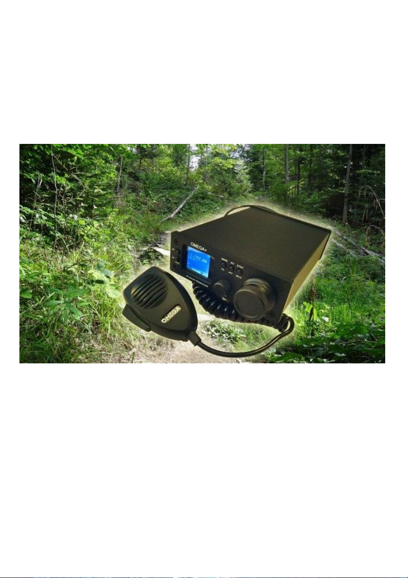
SETUP 14.073.00
A/B
LOCK
band 20m
S0
RX 13,8V
LSB

OMEGA+
CENTER FREQUENCY
XF 2,45kHz
11998000
SETTING BFO
SETUP 14.073.00
A/B
LOCK
band 20m
S0
RX 13,8V
LSB
6.BFO LSB freq A/B
LOCK
setup
6) BFO LSB freq.
A/B
LOCK
setup
5) BFO USB freq.
11.999.50
^
-- turn VFO knob
USB +1,5kHz
LSB - 1,5kHz
center freq.
quarz filter + 1,5kHz
-- press and hold 1 second
button
button
-- press and hold 1 second
A/B
LOCK
setup
5) BFO USB freq.
5.BFO USB freq
-- press and hold 1 secondbutton
-- turn VFO knob
center freq.
quarz filter - 1,5kHz
A/B
LOCK
setup
6) BFO LSB freq.
11.996.50
^
A/B
LOCK
setup
1)exit setup
1.exit setup
-- turn VFO knob A/B
LOCK
setup
1)exit setup
save and exit
save and exit
4
to enter SETUP press simultaneously
and buttons and hold 5 seconds.
In SETUP mode: to select option turn vfo knob, to enter
option press and hold , to save changes press and hold .
button
-- press and hold 1 second
-- press and hold 1 secondbutton
button
-- press and hold 1 second

SETTING CW
SETUP 14.073.00
A/B
LOCK
band 20m
S0
RX 13,8V
LSB
8 CW speed
-- turn VFO knob
A/B
LOCK
setup
7) CW release
7.CW release
-- turn VFO knob
-- turn VFO knob
A/B
LOCK
setup
8) CW speed
A/B
LOCK
setup
7) CW release
1 - 300
9 CW shift A/B
LOCK
setup
9) CW shift
A/B
LOCK
setup
8) CW speed
1 - 300
A/B
LOCK
setup
300 - 1900 Hz
9) CW shift
5
-- press and hold 1 secondbutton
button
-- press and hold 1 second
button
-- press and hold 1 second
-- press and hold 1 secondbutton
button
-- press and hold 1 second
to enter SETUP press simultaneously
and buttons and hold 5 seconds.
In SETUP mode: to select option turn vfo knob, to enter
option press and hold , to save changes press and hold .

ANT MIC
KEY EXT.SP
C+
-
13,8V
REAR PANEL
1. ANT - connect the HF/50MHz/70MHz antenna
2. KEY - 3,5” 3 pole conector plug for connecting stright key or paddle for CW operation
3. 13,8V - connect a regulated 13,8V DC power source
4. EXT-SP- connect the external speaker, use special adapter
5. MIC - connect the microphone, or digi mode
ANT MIC
KEY EXT.SP
C+
-
13,8V
OMEGA
ANTENNA
POWER SUPPLY DC
13,8 V max 2A
8ohm / 2W
1
2
3
EXTERNAL SPEAKER
DIGI MODE OMEGA+
6

ANT MIC
KEY EXT.SP
C+
-
13,8V
IN OUT
LINE IN.
EXIT SP / line out
PC
DIGI MODEM
OMEGA+
DIGI MODEM
7
Use the microphone connector to connect OMEGA+ DIGI MODEM.
Connect the DIGI MODEM IN socket to speaker Jack socket in computer.
Connect the DIGI MODEM OUT socket to line-in Jack socket in computer.

PROCESSOR
OUTPUT VOLTAGE LEVEL
INPUT VOLTAGE ( MIC)
P3 COMPRESSION
P1 P2
EXT.SPK
SPK 8 ohm/2W
IN
OUT
AUDIO SPK. Filter
ANT MIC
KEY EXT.SP
C+
-
13,8V
SPEAKER FILTER
8
Install the microphone processor unit to level out large fluctuations in your voice while you speak.
Use P1 to set input signal level.
Use P2 to set output signal level.
Use P3 to set compression level.
Use the external speaker filter to selectively cut high frequencies of AF output signal.
Connect the SPEAKER FILTER IN socket to speaker Jack socket in the radio.
Connect the speaker to SPEAKER FILTER OUT socket.

EX-SP 8 OHM
1
2
3
4
5
6
7
+9 V TX
1
2
3
4
5
6
7
+9 V RX
PTT
1
2
3
4
5
6
7
++
1
2
3
4
5
6
7
MIC
EX-SP 8 OHM
1
2
3
4
5
6
7
Mini jack 3,5mm stereo Mini jack 3,5mm stereo
Straight KEY
9
CONNECTING PERIPHERAL EQUIPMENT

10
note
This manual suits for next models
1
Table of contents