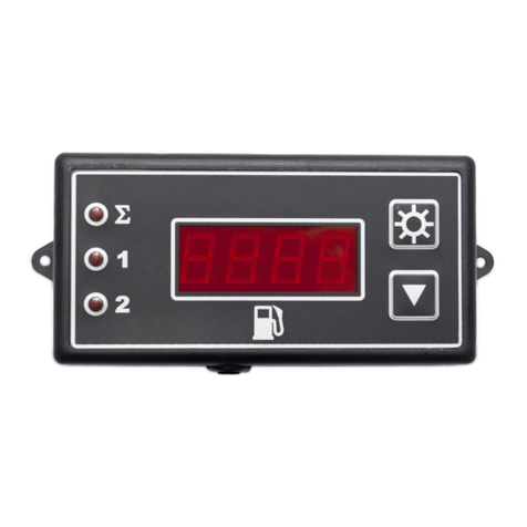
Omnicomm LLS 20230 User manual

Omnicomm LLS 20230 Fuel
Tankers Installation Guide
IG LLS 20230: Installation, Launch, Setup, and Control Guide
17.04.2019

Contents
General
4
Abbreviations and Symbols
5
Safety
5
Preparing for Installation
5
Product Completeness Check
5
Selection of Location to Install the Product
6
Selection of Location to Install BIS 20240 (LLS20230)
7
Preparation of the Fuel Tank for Product Installation
7
Product Cutting to Match the Specific Fuel Tank
10
Setting the Product with Omnicomm Configurator
11
Empty/Full Calibration
12
Configuring General Settings
12
Installation and Deinstallation
13
Product Installation
13
Installing BIS 20240 (for LLS 20230)
16
Connection
17
Requirements for Cable Laying
17
Installing the Fuse
18
Calibrating Fuel Tank
19
Commissioning of Installed and Connected Equipment
20

Sealing
20
Installing a Protective Sealing on the Product
20
Installing Protective Sealings on Connectors
21
List of Commissioning Documents and Document Processing Procedure
22
Appendix A. Terms and Definitions
23
Appendix B. Required Equipment and Tools
24
Appendix C. Installing Nut-Type Rivets
26
Appendix D. Connecting the Product to a PC
29
Appendix E. Procedure for Circular Tank Preparation for Product Installation and Installation
Process
30
Appendix F. BIS 20240 Installation Dimensions
32
Appendix G. Diagram of Product(s) Connection with an External Device
33
Appendix I. Example of Setting Offset Values and Measurement Range
35
Appendix H. Diagrams for Connection to Installed Terminating Resistors
36
Appendix J. Sealants Recommended for Installation of the LLS Fuel Level Sensors
39
Appendix K. Measuring Part Strengthening for LLS Fuel Level Sensors
40
Appendix L. Installing LLS 20230 Fuel Level Sensors 3 to 6 m in Length
46
Appendix M. Strengthening Flange for LLS 20230 Fuel Level Sensor
49

Omnicomm LLS 20230 Fuel Tankers
Installation Guide
General
This manual outlines the rules and procedures for installation, start-up, setting and
connection of fuel level sensor LLS 20230 (hereinafter - product), as well as calibration
procedure for a fuel tank with an installed sensor.
The Omnicomm LLS 20230 fuel level sensor is installed on special types of equipment
or on stationary fuel tanks and storages, which require equipment explosion
protection and have the “0ExiaIIBT6X” explosion protection label. The LLS 20230 fuel
level sensor shall operate only with the Omnicomm BIS 20240 spark protection unit,
produced by Omnicomm
Recommendations for assembling LLS 20230 fuel level sensors with the length from 3
to 6m, are given in the Appendix L.
Installation Works List
1) Checking completeness (Paragraph 3.1)
2) Selection of location to install the product (Paragraph 3.2)
3) Choosing the BIS 20240 installation place (Paragraph 3.3)
4) Preparation of the fuel tank for installation (Paragraph 3.4)
5) Product cutting to match the specific fuel tank
6) Configuring the Product with Omnicomm Configurator (Paragraph 3.6)
7) Product installation (Paragraph 4.1)
8) Installation of BIS 20240 (for LLS 20230) (Paragraph 4.2)
9) Product setting depending on the interface connecting it with an external device
(Paragraphs 5.1 and 5.2)
10) Preparation and laying of cable to connect the product with an external device
(Paragraphs 5.3 and 5.4)
11) Fuse installation (Paragraph 5.5)
12) Fuel tank calibration (Paragraph 5.6)
13) Sealing (Paragraph 7.1)
A list of required equipment and tools is provided in Appendix B (Table 1)
4
General

Abbreviations and Symbols
BIS 20240 — stabilitron-based spark protection unit;
PS — power supply;
OS — operating system;
PC — personal computer;
Software — software;
VH — vehicle;
L — LLS fuel level sensor working length (mm);
L1 — working length of the sensor after cutting to match the specific fuel tank(mm);
M — measurement range (non-dimensional value);
N — numeric code corresponding to measured level value (non-dimensional value);
CNT1 — lower limit of level measurement (non-dimensional value);
CNT2 — upper limit of level measurement (non-dimensional value).
Safety
Only personnel who completed a training course with manufacturer’s authorized
service company and were subsequently certified by them are allowed to carry out
installation and start-up works.
During installation and start-up works it is requested to follow safety requirements
specified in operational documentation of the producer of the vehicle on which the
product will be installed, as well as the requirements of regulatory documents
applicable to this type of equipment.
Preparing for Installation
Product Completeness Check
1) Open up the packaging. Check completeness as per the datasheet. In case the
product does not match the set of components listed in the passport, such a
mismatch is resolved by the manufacturers or their representatives.
2) Perform visual check of the Product. The Product must have no visible damages. In
case a damage is found, the Product must be replaced at the manufacturing facility.
5
Abbreviations and Symbols

Selection of Location to Install the Product
1) The product should be installed, depending on geometric shape of the tank, at the
locations shown in the figures (Figure 1, Figure 2, Figure 3). Product installation at
these locations ensures fuel level independence of vehicle inclination.
2) If the Product cannot be installed in any of places specified in Figures (Figure 1,
Figure 2, Figure 3), the installation place must be as close to any of the specified as
possible.
3) Product installation at the locations other than shown in the figures (Figure 1,
Figure 2, Figure 3), may cause fuel level dependence on vehicle inclination. For
example, for vehicles operating on the high-relief landscape this will mean either
overrated or underrated fuel level values.
Installation of two products in one fuel tank allows to significantly reducing fuel level
dependence on vehicle inclination. Two products should be installed at the locations
shown in the figures (Figure 4, Figure 5)
6
Abbreviations and Symbols

Selection of Location to Install BIS 20240 (LLS20230)
1) Installation of BIS 20240 must be carried out outside of explosion hazard zone, on a
smooth surface (e.g. cabin).
2) While selecting the location for installation, take into consideration the length of
the cable intended to connect stabilitron-based spark protection unit BIS 20240 with
an external device (e.g. FMS).
Note. Connection of BIS 20240 with fuel level sensor LLS 20230 should be made only
by cable KTZ-XX produced by Omnicomm, where XX – cable length (which can be
chosen within the range from 10 to 25m).
Preparation of the Fuel Tank for Product Installation
1) When preparing the holes for installation of LLS fuel level sensors:
If the fuel tank is used for diesel fuel, it is recommended to fill the tank with diesel
fuel to the full before drilling holes — this will minimize the vapor content inside.
If the fuel tank is used for gasoline, it should be steamed.
When drilling holes without preliminary steaming (appropriate only for tanks used
for diesel fuel without any corrosive impurities), it is recommended to coat bimetal
bits or drill with grease oil or lithium grease, which will prevent sparking during
drilling.
If the tank filler neck can be dismantled, tank steaming is not required. Dismantle
the tank filler neck and perform installation works far from the fuel tank.
7
Abbreviations and Symbols

2) Prepare the fuel tank for fitting works following the manufacturer's specification
and other safety regulations appropriate to this type of works.
3) Determine the fuel tank type and prepare it accordingly. Fuel tank types:
a. Plastic or metal tank with the wall thickness under 3 mm
The tanks which shape corresponds with the figure (Figure 2) should be prepared in
accordance with Appendix E. Prepare the tank for fixing the product by rivets.
Drill holes in the tank: the central hole - by a bi-metal crown ø35mm and mounting
holes - by a drill ø7mm as shown in the figure (Figure 7).
Install the rivets in the prepared holes ø7mm with the help of a riveter. A detail
description of rivets installation is given in Appendix C.
8
Abbreviations and Symbols

It is not recommended to use self-tapping screws to fix the product onto a metal or
plastic tank with the wall sickness under 3mm. This type of fixation cannot ensure
reliability of product attachment to the tank.
b. Metal tank with wall thickness over 3mm
Prepare the tank for product installation on a threaded joint.
The tanks which shape corresponds with the figure (Figure 2) should be prepared in
accordance with Appendix E.
Drill holes in the tank: the central hole - by a bi-metal crown ø35mm and mounting
holes - by a drill ø4mm as shown in the figure (Figure 8).
Make an М5 thread with the help of an М5 tap.
9
Abbreviations and Symbols

c. Plastic tank with wall thickness over 3 mm
Drill holes in the tank: the central hole - by a bi-metal crown ø35mm and mounting
holes - by a drill ø4mm as shown in the figure (Figure 9).
Product Cutting to Match the Specific Fuel Tank
1) Measure the depth of the tank by moving a measuring bar down into the central
hole intended for the sensor.
10
Abbreviations and Symbols

2) On the working length of the product L, measure length L1 equal to the depth of
the tank minus 20mm.
Minimum allowable length of the measuring probe cutting is 150 mm.
4) Cut the product at length L1 by a hack-saw so that the line of the cut is strictly
perpendicular to the longitudinal axis of the product (Figure 10).
5) Fill the 1/4 to 1/5 of the sealing cap with a sealant (supplied). Recommended
sealants are listed in the Appendix J.
6) Put the plastic isolating cap included into the product delivery set on the central
rod of the product.
Note: When using the sensor without cutting, it is necessary to take off the rubber
transportation cap and put on the plastic isolating cap using sealant.
Setting the Product with Omnicomm Configurator
Connect the Product to the PC following the connection diagram (see Appendix E),
using the REUSABLE TOOL-UNU (Figure 11) or Omnicomm UNU-USB (Figure 12).
11
Abbreviations and Symbols

Run Omnicomm Configurator. In the window (Figure 13) select equipment — “Sensor”.
If the message “Equipment not found” is displayed in the main window, try changing
connection configuration or operation mode.
Empty/Full Calibration
Perform calibration with fuel which the fuel level sensor will operate in.
1) Pour fuel into the measuring container
2) Immerse the sensor in fuel, to the full length of the measuring probe
3) Wait for the green indicator “Stable” to appear. Press “Full” to set the value
corresponding to a full tank
4) Take the sensor out of the container and wait while fuel will be flowing off the
measuring probe for 1 minute. Press “Empty” to set the value corresponding to an
empty tank
5) Press “Save”
Configuring General Settings
12
Abbreviations and Symbols

“Settings” tab, “Configurable Parameters” section:
“Network address” (1 to 254) – set the sensor network address. If several sensors are
connected to one external device, each of them should have unique network
addresses.
“Max. level (1…4095)” — select the maximum sensor reading. Default value – 4,095.
“Min. level (0…1023)” — select the minimum sensor reading. Default value – 0.
“Filtration” – set the output signal filtration parameters:
“No” – no filtration. Used for filtration by an external device.
“Minimum” filtration is used when the device is installed in stationary fuel storages
and non-mobile machinery
“Average” filtration is used when the vehicle operates under normal road
conditions
“Maximum” filtration is used when the vehicle operates under harsh road
conditions
“Automatic data output” – select:
“No output” – no data output without request
“Binary” – autonomous binary data output
“Character” – autonomous character data output
“Data output interval” (1 to 255 seconds) – set the autonomous data output interval
“Heavy exploitation conditions” mode – switch on to enable additional measurement
filtration that considers harsh conditions
“Baud rate” – select data exchange rate when communicating with an external device.
Default value – 19200 bit/s.
Installation and Deinstallation
To make the works go smooth, it is recommended to perform product setting prior to
installation works (see Paragraph 5).
Product Installation
13
Installation and Deinstallation

For tanks which shape corresponds with the figure (Figure 2), installation should be
carried out in accordance with Appendix E.
1) Put the gasket included into the product delivery set on the measuring part of the
product (Figure 24).
2) Install the product into the tank.
3) Fix the product to the tank by bolts, having preliminary installed the washer and
the spring washer as shown in the figures (Figure 14, Figure 15). The bolts should be
tightened by a spanner.
4) When the product is installed on plastic tanks with wall thickness over 3mm, the
product must be fixed by a self-tapper included into the delivery set. Self-tapper
tightening strength should be such that the rubber washers put on the self-tapping
screws are not crumpled or burst.
5) When installing the Product with the measuring part length over 1.5 m into fuel
tanks of special vehicles (e.g. petrol tankers, diesel locomotives it is necessary to
14
Installation and Deinstallation

ensure that there are no fuel wave shocks during sharp acceleration and breaking
operation of the vehicle. For this purpose, it is recommended to install the products
near wave suppressing partitions, or the measuring part of the LLS fuel level sensor
should be reinforced in one of the following ways: with steel pins (Figure 16, Figure
17); collars or steel rods (Figure 18, Figure 19), or installed onto the flange.
15
Installation and Deinstallation

IMPORTANT! Strengthening the measuring part of the LLS fuel level sensors is only
allowed for removable filler caps. Refer to the Appendices K, L for the detailed
description of methods for strengthening the measuring part of the LLS fuel level
sensors.
Installing BIS 20240 (for LLS 20230)
1) Fix BIS 20240 on selected surface by self-tapping screws or bolts according to
installation dimensions (Figure 35, Appendix F). 2) Make an electric connection of BIS
20240 to the vehicle body or to the Ground bus terminal (with earthed element of
stationary fuel storage structure) with a copper wire with the cross-section of at least
4 mm2.
The electrical resistance of the conductor between the body of BIS 20240 and the
body of the vehicle or Ground bus terminal should not exceed 0.1 Ohm.
16
Installing BIS 20240 (for LLS 20230)

Connection
The Products must be connected to an external device as per the connection diagrams
(see Appendix G).
Two LLS 20230 fuel level sensors can be connected to one BIS 20240 spark protection
unit with the KTZ splitter and two KTZ cables (Figure 41), provided that BIS 20240
voltage is at least 12 V (when connecting BIS 20240 to the on-board power supply,
FTC AVL unit, or third-party AVL unit).
When connecting the BIS 20240 spark protection unit to the battery, the BR15 galvanic
insulation unit (Figure 42) must be used.
Requirements for Cable Laying
1) For installation, use the cables produced by Omnicomm - either those included into
the delivery set or those purchased separately. 2) For connection of the LLS 20230 fuel
level sensor and the BIS 20240 spark protection unit on Zener diodes, use only KTZ-xx
cable (xx stands for the cable length determined at the time of purchase request).
Use of self-made cables or KTZ cable cutting or extension is FORBIDDEN.
3) To connect the BIS 20240 spark protection unit on Zener diodes to an external
device, use a crinkled cable produced by Omnicomm (to be purchased separately). If
needed, the cable connecting with the external device can be either extended or cut.
4) Ensure that cable laying routes are free of heated parts and units of the vehicle to
avoid cable insulation fusing.
5) To prevent cable damage, the cable should be routed in a pipe or duct.
17
Connection

6) Ensure that cable laying routes are free of heated parts and units of the vehicle to
avoid cable insulation fusing.
7) The purposes of connector pin-outs and cable wire colors are illustrated below
(Figure 21).
GND supply circuit (white wire) of BIS 20240 must be connected to the vehicle body
only.
Installing the Fuse
1) The fuse is intended to protect on-board network of the vehicle against short
circuit caused by a breakdown in product wiring.
2) Connect the fuse holder to the feeding cable of the product in the immediate
vicinity of the power circuit of the vehicle.
18
Connection

3) Install the fuse into the fuse holder.
4) When installing the LLS 20230 fuel level sensor with BIS 20240, the fuse is installed
in the power circuit of BIS 20240.
Calibrating Fuel Tank
Fuel tank calibration is required to ensure that numeric code produced by the product
corresponds with the fuel volume in a given fuel tank.
Fuel tank calibration is the process of filling the empty tank with fuel until the tank is
full with certain step of filling, and recording product readings in a calibration table.
The tank may be calibrated by draining.
Calibration of the tank with one Omnicomm LLS sensor: 1. Empty the fuel tank
2. Connect the Omnicomm LLS fuel level sensor to a PC or tablet PC with a UNU device
or UNU-USB, as illustrated in Figures (Figure 11, Figure 12)
3. Run Omnicomm Configurator on a PC or tablet PC Select “Tank Calibration”
operating mode
If the sensor reading column is not displayed, press “Add Sensor”. Select
Omnicomm LLS sensor type. Enter the sensor network address that was set during
configuration.
4. Set the flow interval in liters If the fuel tank geometry is non-linear and/or has
widenings or narrowings, for better accuracy, it is recommended to follow the lower
calibration step by using lower-dosage (higher-resolution) measuring containers.
5. Press “Start/Continue Calibration”
19
Connection

6. Fill in the fuel volume equal to the flow interval Fill using a measuring container or
under control of a fluid flowmeter with the preset interval. The container must have
the metrological calibration test certificate.
7. Press “Add a Row” The filling volume equal to the predefined flow interval will be
displayed in the “Liters” column. The value equal to the filling volume will be
displayed in the “Sensor” column.
8. Press “Add a Row”
9. Repeat steps 7, 8, and 9 pursuant to the number of control points. The minimum
recommended number of control points is 20.
10. Press “Finish the Calibration”
11. Save the calibration table to a calibration file (.ctb)/ an Omnicomm Online file
(.xml)/ to the Terminal/ or to the Indicator, by pressing “Service” - “Export” or F2 button
at the keyboard.
When performing the gauging table export to the Omnicomm Online (.xml) file, the
“Export” window will open. Specify the Omnicomm LLS sensor number to display in
Omnicomm Online.
Calibration of a tank with several Omnicomm LLS 20230 sensors will be similar to
calibrating a tank with one sensor. Before you start the calibration, add the required
number of Omnicomm LLS sensors and enter their network addresses. All sensors are
calibrated at one time. Use a KTZ splitter to connect multiple Omnicomm LLS sensors
to a PC.
Commissioning of Installed and Connected Equipment
Sealing
Installing a Protective Sealing on the Product
Installation of the seal is intended only for the products fixed with the help of bolts.
1) Overlap the holes of the inner ratchet with external holes of the seal.
2) Pass the sealing wire through the holes in two bolts, wrap the wire around the
metal hose as it is shown in the figure (Figure 23), and pass the ends of the wire
through the holes of the seal.
3) Spin the wire by rotating the handle of the ratchet clockwise to achieve complete
tension.
4) Break off the ratchet handle.
20
Connection
Table of contents
Other Omnicomm Measuring Instrument manuals
Popular Measuring Instrument manuals by other brands

LMI
LMI 241 Series Configuration and Mastering Instruction

pyroscience
pyroscience MUX2 user manual

Endress+Hauser
Endress+Hauser Turbimax CUS52D operating instructions

Scanse
Scanse SWEEP V1.0 Users manual andtechnical specification

Sylvac
Sylvac SYLVAC-SCAN S145 quick start

Baltech
Baltech VP-3470 Operation manual