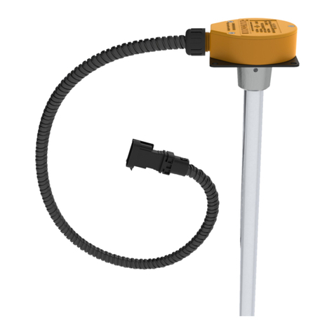
Omnicomm LLD User manual

Omnicomm LLD fuel volume
indicator
User Manual
Omnicomm Configurator 6
26.04.2019

Omnicomm LLD fuel volume indicator
General information
Omnicomm LLD fuel volume indicator is intended to display fuel volume of
remaining fuel in the tanks of the vehicles, diesel generators and fuel storages.
In addition, Omnicomm LLD fuel volume indicator enables control over one of the
following parameters:
volume of fuel filled in the tank during refueling, vehicle speed (with Omnicomm
terminals only);
volume of fuel dispensed by fuel tanker truck (with Omnicomm Profi terminals
only);
value from Omnicomm terminal universal input.
Omnicomm LLD indicator shall only be used with Omnicomm LLS fuel level sensors
through RS-485 interface.
While installing this device, you should observe the safety precautions and measures,
as well as meet the requirements of the regulatory documentation for this type of
works.
3
General information

Setting up
Connect the Omnicomm LLD indicator to the PC using UNU or
Omnicomm UNU-USB according to the scheme:
or
4
Setting up

Launch Omnicomm Configurator:
Select equipment – «Indicator».
1. Specify the rate for data exchange via the RS-485 interface. For firmware update,
set the data exchange rate to the value of 19200 bit/sec
2. Specify the number of sensors connected to the Omnicomm LLD indicator
3. Specify the network addresses that are set in the Omnicomm LLS fuel level sensors
4. Set the brightness level for the indicator at startup. The following options are
available: maximum, minimum, off. The minimum brightness level is set by default
5. If necessary, set one of the additional parameters (see the «Displaying of the
additional parameter» section)
6. Click on the “Save in the indicator” button
In the “Calibration” section, fill out the calibration table for each Omnicomm LLS fuel
level sensor, or download it from the previously saved file by clicking «Import».
5
Setting up

To save the calibration table, click «Export».
Installation and Connection
While installing the Omnicomm LLD fuel volume indicator with the help of screws,
drill two 3.2 mm diameter fixation holes according to the installation dimensions, on
the back side of a place of installation install a washer and a nut, which are both
included in the delivery set:
While installing the Omnicomm LLD fuel volume indicator with the help of self-
tapping screws, drill two 2.5 mm diameter fixation holes according to the installation
dimensions.
6
Installation and Connection

The connection the Omnicomm LLD indicator to the Omnicomm LLS sensor, terminal
or on-board network of the vehicle is generated according to the scheme :
If it is necessary to connect two Omnicomm LLS sensors, it is recommended to use
two KTZ splitters and two KTZ cables.
7
Installation and Connection

Purposes and colors of the wires in the installation cable:
Name of signal Type of wire
RS-485 A Orange-white
RS-485 B White-blue
RS-232 Tx Pink
RS-232 Rx Gray
+V power Brown
Ground White
Purposes and colors of the wires in the cable of the Omnicomm LLD indicator when
connecting without a connector:
Name of signal Type of wire
RS-485 A Orange-white
RS-485 B White-blue
+V power Brown
Ground White
8
Installation and Connection

Purpose of the Indicator Lights
Displaying Fuel Volume
The Omnicomm LLD indicator displays the value of fuel volume in the tank.
Shortly pushing the button will allow you to go to the next value viewed on the
display:
total volume read from both sensors (the Σ LED emits light)
fuel volume read from the 1st LLS sensor (the 1 LED emits light)
fuel volume read from the 2nd LLS sensor (the 2 LED emits light)
Displaying Additional Parameter
Displaying an additional parameter and returning to the default information is
enabled by long-pushing (i.e. longer than 3 s) the button.
If necessary, you can set up one of the additional parameters:
1. Displaying the volume of fuel added during the refueling operation
This parameter allows you to monitor both the total volume of fuel added to the
tank, and the volume of fuel in each tank.
In Omnicomm Configurator, in the «Additional parameter» field, select the «Volume of
refueling» option.
9
Purpose of the Indicator Lights

Before starting the refueling operation, please, switch to the mode of displaying the
additional parameter by long-pushing the button. Start the refueling operation.
The Omnicomm LLD indicator will display the volume of fuel being added to the tank.
Short-pushing the will allow you to go to the next value viewed on the display:
total volume of fuel added (the Σ LED blinking light)
volume of fuel added according to the 1st Omnicomm LLS sensor’s readings (the 1
LED blinking light)
volume of fuel added according to the 2nd Omnicomm LLS sensor’s readings (the 2
LED blinking light)
2. Displaying the value of vehicle speed transmitted from the Terminal
This parameter allows you to monitor the vehicle speed.
In Omnicomm Configurator, in the «Additional parameter» field, select the «Terminal’s
data» option.
Enable the feature of displaying the speed by long-pushing the button.
3. Displaying the value read from the Terminal’s universal input
This parameter allows you to monitor the Terminal’s universal input status or value,
depending on the type of the connected auxiliary equipment.
In Omnicomm Configurator, in the «Additional parameter» field, select the «Terminal’s
data» option.
Enable the feature of displaying the parameter by long-pushing the button.
4. Displaying the volume of fuel dispensed from a fuel tanker truck
This parameter is only available for the Omnicomm Profi 2.0 Terminal, which is
provided with the connected signal pickup device (USS).
In Omnicomm Configurator, in the «Additional parameter» field, select the «Terminal’s
data» option.
Before starting the fuel dispensing operation, please switch to the mode of displaying
the additional parameter by long-pushing the button. Start the fuel dispensing
operation. The Omnicomm LLD indicator will display the volume of fuel being
dispensed through the dispensing nozzle. Short-pushing the button resets the
10
Purpose of the Indicator Lights

displayed value.
The additional parameter can be displayed by default upon switching the
Omnicomm LLD indicator on. For this purpose, in Omnicomm Configurator, in the
«Settings» section, in «The display mode at startup» field, select the «Additional
parameter» option.
To display the vehicle speed, the values read from the universal input and the volume
of fuel dispensed, it is necessary to edit the appropriate settings of the Omnicomm
Terminal.
Technical Specification
Specification Value
Supply voltage, V from + 8 to + 45
Network interface RS-485
Data exchange rate via EIA-485 interface by default, bit/sec 19 200
Calibration table, rows 56
Number of the connectable Omnicomm LLS sensors 2
Ambient operating temperature, ˚С from - 40 to + 70
Overall dimensions, mm 137х61х23
11
Technical Specification

info@omnicomm-world.com
www.omnicomm-world.com
Table of contents
Other Omnicomm Measuring Instrument manuals
Popular Measuring Instrument manuals by other brands

HIOS
HIOS HDP-50 Operation manual

Dakota Digital
Dakota Digital MVX-2011 manual

Hanna Instruments
Hanna Instruments HI 8064 instruction manual

S+S Regeltechnik
S+S Regeltechnik HygraAsreg KH-10 Operating Instructions, Mounting & Installation

Schrack Technik
Schrack Technik KIZ product manual

Campbell
Campbell SR05 product manual