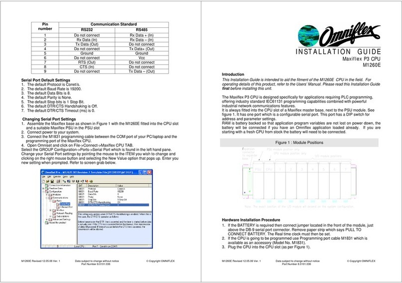
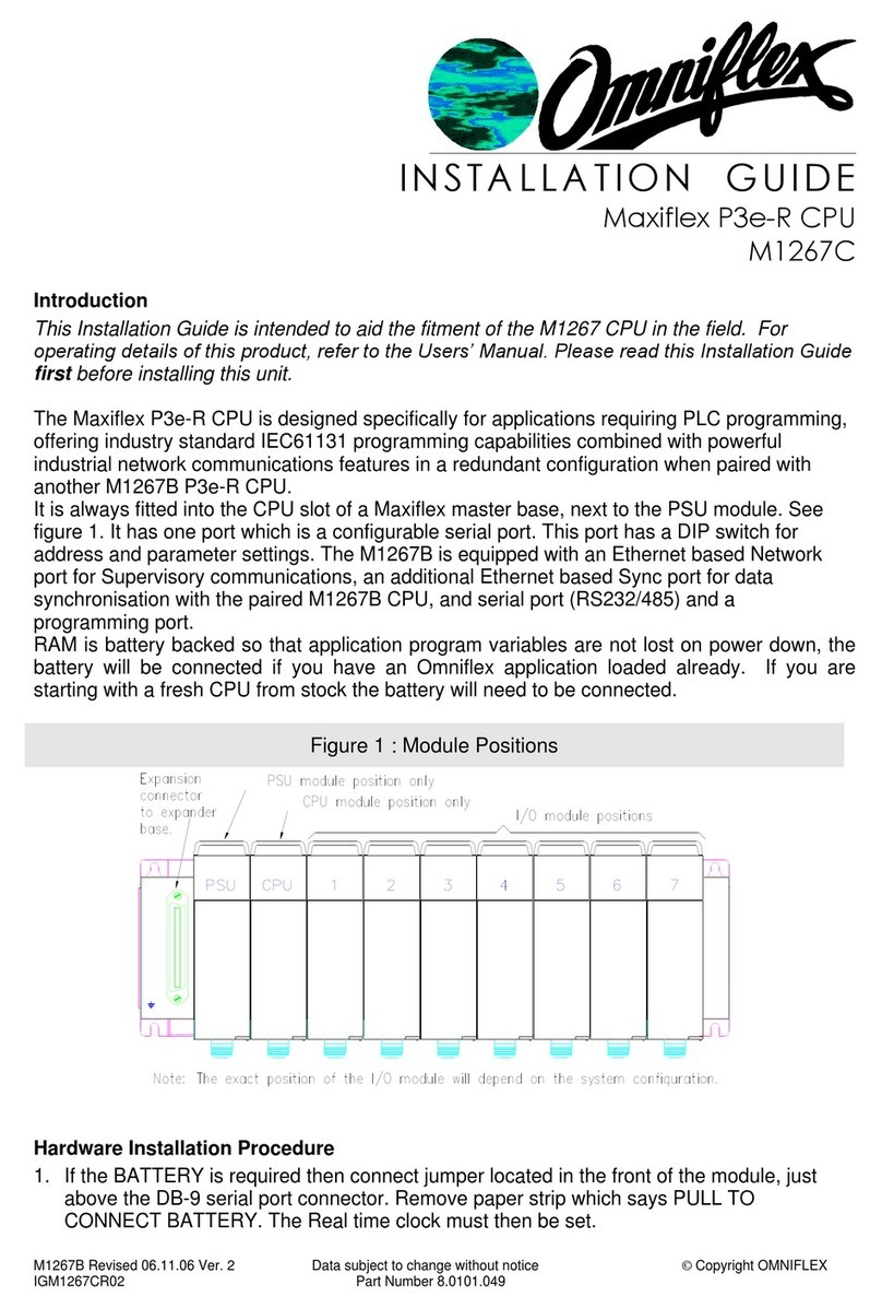
Omniflex M1261F User manual

M1261F Revised 12.05.06 Ver. 2 Data subject to change without notice © Copyright OMNIFLEX
IGM1261FR02 Part Number 8.0101.040
INSTALLATION GUIDE
Maxiflex P3c CPU
M1261F
Introduction
This Installation Guide is intended to aid the fitment of the M1261 CPU in the field. For
operating details of this product, refer to the Users’ Manual. Please read this Installation Guide
first before installing this unit.
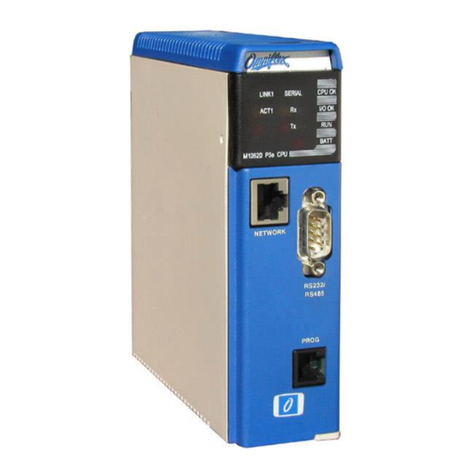
The Maxiflex P3 CPU is designed specifically for applications requiring PLC programming,
offering industry standard IEC61131 programming capabilities combined with powerful
industrial network communications features.
It is always fitted into the CPU slot of a Maxiflex master base, next to the PSU module. See
figure 1. It has one port which is a configurable serial port. This port has a DIP switch for
address and parameter settings.
RAM is battery backed so that application program variables are not lost on power down, the
battery will be connected if you have an Omniflex application loaded already. If you are
starting with a fresh CPU from stock the battery will need to be connected.
Figure 1 : Module Positions
Hardware Installation Procedure
1. If the BATTERY is required then connect jumper located in the front of the module, just
above the DB-9 serial port connector. Remove paper strip which says PULL TO
CONNECT BATTERY. The Real time clock must then be set.
2. If the CPU is going to be programmed use Programming port cable M1831 which is
available as an accessory (Model No. M1831).
3. Plug the CPU into the CPU slot (as per Figure 1).
Software Requirements

M1261F Revised 12.05.06 Ver. 2 Data subject to change without notice © Copyright OMNIFLEX
IGM1261FR02 Part Number 8.0101.040
Omniset is the PC utility that is used to configure the unit.
Cofiguring the Realtime Clock(RTC)
1. Assemble the Maxiflex base as shown in Figure 1 with the M1261 fitted into the CPU slot
and a suitable Maxiflex PSU in the PSU slot
2. Connect power to your system.
3. Connect the M1831 programming cable between the COM port of your PC/laptop and the
programming port of the Maxiflex CPU.
4. Open Omniset and click on File->Connect->Maxiflex CPU TAB.
Select the GROUP Configuration->Ports->Realtime Data->Date/Time which is found in the left
hand pane. Change the RTC settings by pointing the mouse to the ITEM you wish to change
and clicking on the right mouse button and selecting the New Value option that pops up. Enter
you new setting when prompted. Refer to screen grab below.
Table 1: P3 CPU Front Panel Diagnostics
LED Legend
LED Colour
Description
CPU OK
Green
ON - CPU is healthy
OFF or Flashing –No power applied or CPU Faulty
I/O OK
Green
ON - I/O Module status healthy and I/O Manifest is
configured.
FLASHING –I/O Manifest is configured but
disagrees with installed hardware.
OFF –I/O Manifest is not configured.
RUN
Green
ON –user application software is running
OFF –No user application software is running
Flashing –Terminal interaction with CPU
BATT
RED
ON –Internal battery is LOW or not connected.
OFF –Internal battery is good.
SERIAL Rx
YELLOW
ON –data is being received on serial port
OFF –serial port receiver is idle
SERIAL Tx
RED
ON –serial data is being transmitted on serial port
OFF –serial port transmitter is idle
NETWORK Rx
YELLOW
ON –network data is being received
OFF –network receiver is idle

M1261F Revised 12.05.06 Ver. 2 Data subject to change without notice © Copyright OMNIFLEX
IGM1261FR02 Part Number 8.0101.040
81 2 3 4 5 6 7
ON
81 2 3 4 5 6 7
ON
NETWORK Tx
RED
ON –network data is being transmitted
OFF –network transmitter is idle
NETWORK
TOKEN
GREEN
ON –network not connected or setup incorrectly
OFF –network not connected or setup incorrectly
FLASHING EVENLY –network is connected
Table 2: Programming Port Pinout
Signal Name
DB-9
FCC-68 Pin No.
Rx Data from P3
2
4
Tx Data to P3
3
1
Ground Reference
5
2
All other pins are reserved and must not be connected.
NOTE: This information is only necessary if you are making up your own programming cable.
If you are using a M1831 Programming port cable, simply connect the programming cable
between the CPU and PC as per the connectors of the programming cable.
Table 3: Switch 1 Set-up (Serial Port)
Communications Protocol
Serial Port Dipswitch setting
Modbus Protocol (Slave device):
Transmission Mode: ASCII
Baud rate: 9600
Data bits: 7
Parity: none
Stop bits: 1
Address: see dipswitch
Switches 1-5: Modbus ID
Switches 6-8: Protocol
Switch 8 ON = Modbus default
Conet/s Protocol
Transmission Mode: RTU
Baud rate: 19200
Data bits: 8
Parity: none
Stop bits: 1
Address: see dipswitch
Switches 1-5: Conet ID
Switches 6-8: Protocol
Switch 7 ON = Conet/s default
The default operation is to use the serial port for standard communications allowing the user to
get the CPU up and running quickly and easily both on the test bench and in the field. In this
case the Serial Port Dipswitch beneath the male, sub-miniature DB-9 connector has the above
default configurations. The serial port is also software configurable using the Omniset utility or
application program, but when switch 7or 8 of the dipswitch is turned ON, then the dipswitch
setting overrides the software configuration. To restore the settings to the software
configuration, simply set switch 7 or 8 of the dipswitch OFF.
Table 4: Serial Port Pinout
The M1261 P3c CPU allows jumperless conversion between RS232 and RS485
communications. By simply following the appropriate pinout of the serial port connector below

M1261F Revised 12.05.06 Ver. 2 Data subject to change without notice © Copyright OMNIFLEX
IGM1261FR02 Part Number 8.0101.040
it is possible to connect the CPU in either mode without making any hardware or software
changes to the CPU.
Pin
number
Communication Standard
RS232
RS485
1
Do not connect
Rx Data + (In)
2
Rx Data (In)
Rx Data –(In)
3
Tx Data (Out)
Do not connect
4
Do not connect
Tx Data+ (Out)
5
Ground
Ground
6
Do not connect
Vcc
7
RTS (Out)
Do not connect
8
CTS (In)
Do not connect
9
Do not connect
Tx Data –(Out)
Serial Port Default Settings
1. The default Protocol is Conet/s.
2. The default Baud Rate is 19200.
3. The default Data Bits is 8.
4. The default Parity is None.
5. The default Stop bits is 1 Stop Bit.
6. The default DTR/CTS Handshaking is Off.
7. The default DTR/CTS Timeout (ms) is 0.
Changing Serial Port Settings
1. Assemble the Maxiflex base as shown in Figure 1 with the M1261 fitted into the CPU slot
and a suitable Maxiflex PSU in the PSU slot
2. Connect power to your system.
3. Connect the M1831 programming cable between the COM port of your PC/laptop and the
programming port of the Maxiflex CPU.
4. Open Omniset and click on File->Connect->Maxiflex CPU TAB.
Select the GROUP Configuration->Ports->Serial Port which is found in the left hand pane.
Change your Serial Port settings by pointing the mouse to the ITEM you wish to change and
clicking on the right mouse button and selecting the New Value option that pops up. Enter you
new setting when prompted. Refer to screen grab below.

M1261F Revised 12.05.06 Ver. 2 Data subject to change without notice © Copyright OMNIFLEX
IGM1261FR02 Part Number 8.0101.040
81 2 3 4 5 6 7
ON
81 2 3 4 5 6 7
ON
Conet Pin Connections to DB9 on CPU Front
Pin Number
Description
1,3,4,6,7 and 9
No Connection
2
Signal +
5
Signal -
Switch 2 Set-up Conet node ID - SW2-1 to SW2-7
Each device on the same Conet network is given a unique identity
number known as the node ID. The node ID starts from 1 for the first
device (node) and increments by one for each node on the Conet
network up toa maximum of 127. The node ID is set in binary with
SW2-7 the MSB (Most Significant Bit).e.g. Node 5 =1010000. Table
below showsnode address of 2. (0100000)
Communications
Protocol
Dipswitch setting
Conet (Normal mode):
Baud rate: 62 500
Switches 1-7: Conet ID
Switch 8: Baud Rate
Switch 8 OFF = 62.6 kbaud
Conet (Slow mode):
Baud rate: 7800
Switches 1-7: Conet ID
Switch 8: Baud Rate
Switch 8 ON = 7.8 kbaud

M1261F Revised 12.05.06 Ver. 2 Data subject to change without notice © Copyright OMNIFLEX
IGM1261FR02 Part Number 8.0101.040
Conet Baud Rate –SW2-8
This switch is used to set the Conet Baud Rate. Two options are available :- Normal Mode N
= 62,5kbaud and Slow Mode S = 7,8kbaud.
Conet node connection C6169 Conet Terminators
To connect the M1261 to the Conet data highway the CONET termination board is used to tee off
from the network to the CPU. Figure 4 shows the connection for the termination board. If the line is
to be terminated, a resistance equivalent to the characteristic line impedance is fitted between
terminals 8 and 10 or 4 and 6 depending on which terminals the transmission line is connected to.
The network must only be terminated the ends: at the first node and at the last node. The Conet
connectionto the CPU is made to terminals 1 and 3 on the termination board.
Figure 4: Conet Termination Board Model C6169
This manual suits for next models
1
Other Omniflex Computer Hardware manuals
Popular Computer Hardware manuals by other brands

Blue Technix
Blue Technix CM-i.MX27-C-C-Q26S128F32N512 Hardware user manual

ARTESYN EMBEDDED TECHNOLOGIES
ARTESYN EMBEDDED TECHNOLOGIES SharpMedia PCIE-8120 Assembly, Installation and Use

A4Tech
A4Tech RN-10 user manual

Multitech
Multitech MT5600SMI brochure

Corsair
Corsair AF RGB ELITE manual

ELAN DIGITAL SYSTEMS
ELAN DIGITAL SYSTEMS AD135 user guide