Omniflex Maxiflex P3 M1260E User manual

Maxiflex P3
Process Automation Controller CPU
User’s Manual

Maxiflex P3 PAC User Manual
2
-© Omniflex
UMM126XR18.pdf
Date
Revi
sion
Comments
March 2003
1
Initial Issue
March 2003
2
Ethernet configuration updated
April 2003
3
Minor Corrections
April 2003
4
Ethernet Addressing updated
April 2003
5
Battery Link information added
April 2003
6
Typographical corrections
May 2003
7
DITcopy Function Block updated and Network DIP Switch
not active on A versions of the product.
April 2004
8
Added Subscriptions, Modbus Master and ISaGraf
programming extension. Model ‘D’.
Sept 2004
9
Added more Content for Modbus Master. Added new DIT
access function blocks to ISaGraf programming
extensions.
March 2005
10
Added remote I/O support & redundant options.
October 2005
11
Added Network Offset screen grab to section 10.4.2
August 2006
12
DIT Numbers in Local & Remote Racks Corrected
November 2006
13
Added M1760/1 32 SOE Module, Queue Service
December 2013
14
Corrected Battery Link Default Connection
September 2014
15
Increased supported number of Remote Racks. Updated
hardware revisions.
May 2016
16
Added reference to the Maxiflex A3e CPU.
October 2018
17
Upped the CPU versions due to TSM functionality
February 2019
18
Previous version showed markup
SOFTWARE COPYAVAILABLE
This manual is available in printed form or in Adobe Acrobat pdf format.
The pdf file is named UMM126XR18.pdf

Maxiflex P3 PAC User Manual
3
-© Omniflex
UMM126XR18.pdf
COPYRIGHT AND PROTECTIVE NOTICES
1. The Copyright of this document and the associated drawings, is the property of Omniflex and
is issued on condition that it is not copied, reprinted or reproduced or transmitted in any form or by any
means, electronically, photocopying, mechanical or otherwise, nor its contents disclosed, either wholly
or in part, without the consent in writing of, or in accordance with the conditions of a contract with
Omniflex.
2. The publication of information in the document does not imply freedom from patent or other
protective rights of Omniflex or others.
3. Although every intention is made to ensure that performance figures and data are accurate the
company reserves the right to alter without notice any product or specification. Performance figures
and data must therefore be specifically confirmed by the company before they become applicable to
any tender, order or contract.
4. In the case of electrical components, enough data is included in the drawings to allow
maintenance of the equipment. However, if component availability or substitution information is
required please consult the factory for assistance, as it is impossible to include data on every
component in this document.
5. This product is sold without liability for consequential loss of any description.

Maxiflex P3 PAC User Manual
4
-© Omniflex
UMM126XR18.pdf
SCOPE
This User Manual provides information on how to install, configure and use the full range of
Maxiflex P3 Process Automation Controller CPU’s.
Note : This manual also applies to the Maxiflex A3e CPU (Maxilarm) which is based on the P3
CPU. The standard features are common to both CPU types. For specific Maxilarm functionality,
please refer to the Maxiflex A3 User Manual.
This manual does not cover the fundamentals of the IEC61131-3 programming languages, nor the
Omniflex ISaGraf Programmer’s Workbench. This information is available separately in the
manuals supplied with that product, but programming features specific to the P3 CPU’s are
included in this manual.
This manual covers the following product Models:
Model
Description
M1260E
P3 CPU with RS232/485 Serial Port
M1261E
P3c CPU with RS232/485 Serial Port and Conet/c
Twisted Pair Network Port.
M1262F
P3e CPU with RS232/485 Serial Port and Conet/e
10/100 Ethernet Network Port
M1264A
A3c CPU with RS232/485 Serial Port and Conet/c
Twisted Pair Network Port .(standard features only)
M1265A
A3e CPU with RS232/485 Serial Port and Conet/e
10/100 Ethernet Network Port (standard features only)
M1267B
P3e-R CPU with RS232/485 Serial Port and 10/100
Ethernet Port.
Introduction
The MAXIFLEX P3 & A3 range of Process Automation Controller (PAC) CPU’s is designed for
general industrial control applications including process control, PLC, telemetry and remote I/O
applications. These CPU’s combine powerful industrial network communications capabilities with
ease of use and powerful programming features.
All I/O and configuration data variables are automatically accessible through up to 65,000 Data
Interchange Registers in a single virtual “Data Interchange Table”, allowing the implementation of
Remote I/O systems “out of the box” without programming.
For local control and data manipulation, the Maxiflex P3 & A3 PAC CPU’s can be programmed in
one or more of the standard IEC61131-3 programming languages using the powerful Omniflex
ISaGraf Programmer’s Workbench.
Many other features such as a built-in real-time clock, battery backup for temporary dynamic data,
and a MODBUS (Master or Slave) or Conet/s equipped RS232/485 serial port are standard in
these products.

Maxiflex P3 PAC User Manual
5
-© Omniflex
UMM126XR18.pdf
Powerful features such as automatic I/O module recognition and scanning, remote programming,
and a versatile Remote Data Subscription Service, all contribute to making the P3 CPU a “plug-
and-work” product that dramatically reduces system engineering time.
Following the ISO OSI 7-layer model, these CPU’s includes powerful inter-network routing
capability for retrieving data from the corners of the factory in very large, geographically spread-out
installations. This capability allows many dissimilar network types to be linked to create a seamless
factory intranet, quite often without the need to install special network cabling.
The MAXIFLEX P3-R CPU’s are designed specifically for redundant remote I/O and control
applications, where high availability is required in hot standby configurations.

Maxiflex P3 PAC User Manual
6
-© Omniflex
UMM126XR18.pdf
Table of Contents
1. Glossary of Terms............................................................................................................... 11
2. General Description of the P3 & A3 CPU’s........................................................................ 15
2.1 Front Panel LED Indicators:.........................................................................................15
2.2 Communication Ports ..................................................................................................16
2.3 I/O Module support......................................................................................................17
2.4 Dual Redundant Operation..........................................................................................17
2.5 CPU Functions ............................................................................................................17
3. CPU’s and the MAXIFLEX Architecture............................................................................. 20
3.1 General System Architecture.......................................................................................20
4. Installing the CPU ............................................................................................................... 23
4.1 Connecting the Internal Battery ...................................................................................23
4.2 Connecting the memory battery backup ......................................................................23
4.3 Installing the CPU on the Maxiflex base ......................................................................24
4.4 Connecting the Programming port (all models)............................................................24
4.5 Connecting the Serial port (all models)........................................................................24
4.6 Connecting the Conet/c network port...........................................................................25
4.7 Connecting the Ethernet network port .........................................................................25
4.8 Connecting the Watchdog Relay Output Contact.........................................................25
4.9 Applying power for the first time...................................................................................26
4.10 Front-Panel LED Indicators Explained.........................................................................26
5. I/O Module Management & Scanning Explained...............................................................28
5.1 Number of I/O Modules................................................................................................28
5.2 Automatic I/O Module Identification .............................................................................28
5.3 The I/O Module List .....................................................................................................28
5.4 Automatic I/O Scanning...............................................................................................29
6. The Data Interchange Table explained..............................................................................30
6.1 DIT Table Overview.....................................................................................................30
6.2 DIT Table Layout.........................................................................................................30
6.3 CPU Dynamic Data Space (0-29,999).........................................................................31
6.4 Intelligent Modules in I/O Slots 1 to 15 (30,000-59,999) ..............................................31
6.5 CPU Configuration (Static) Data Space (60,000-65,499).............................................32
6.6 DIT Access to I/O Module Data ...................................................................................33
7. I/O Module DIT Register Reference....................................................................................38
7.1 M1101A –24VDC/12V Solar 3A Charger/Power Supply..............................................38
7.2 M1102B –DC L - 24Vdc Logic Power Supply .............................................................38
7.3 M1104A –DC LF - 48Vdc Logic/Field Power Supply...................................................38
7.4 M1151C –AC LF - 115/230Vac Logic/Field Power Supply..........................................39
7.5 M1152B –AC LC - 115/230Vac Logic Power Supply/Charger. ...................................39

Maxiflex P3 PAC User Manual
7
-© Omniflex
UMM126XR18.pdf
7.6 M1321A –8DI-C - 8 way Individually Isolated Contact Input Module...........................39
7.7 M1322A - 16DI - 16 way Digital Input Module (9-30Vdc) M1323A - 16DI - 16 way Digital
Input Module (18-60Vdc) ...........................................................................................................40
7.8 M1326A –32DI –32 way Digital Input Module............................................................40
7.9 M1330A –8DI8RO 8way Digital Input /8 way Relay Output Module............................41
7.10 M1341B –16DO –16way Digital Output Module.........................................................41
7.11 M1342A –32DO –32way Digital Output Module.........................................................42
7.12 M1372A –8RO –8way Relay Output Module .............................................................42
7.13 M1403A –16AI –16way Analogue Input Module........................................................43
7.14 M1412A –8AO –8 way Analogue Output Module.......................................................43
7.15 M1431B –8VC ISO –8 way Isolated Voltage/Current Input Module...........................44
7.16 M1432C –8TC ISO –8 way Isolated Thermocouple/milliVolt Input Module................47
7.17 M1433B –6RTD ISO –6 way Isolated Resistance Bulb Input Module........................50
7.18 M1760A –32SOE –32 way Sequence of Events Input Module - 24V Input M1761A –
32SOE –32 way Sequence of Events Input Module - 48V Input ...............................................52
8. The Subscription Service Explained .................................................................................55
8.1 Introduction to Subscriptions........................................................................................55
8.2 Setting up subscriptions...............................................................................................55
8.3 Number of subscriptions allowed.................................................................................57
8.4 Subscription Application Example................................................................................57
9. Queue Service Explained ...................................................................................................59
9.1 Introduction to the Queue Service ...............................................................................59
10. Modbus Master Operation Explained ................................................................................ 60
10.1 Introduction to Modbus Master Driver..........................................................................60
10.2 Modbus Master Parameters ........................................................................................60
10.3 Query Configuration.....................................................................................................62
10.4 Query Triggers.............................................................................................................63
10.5 Status DIT Registers....................................................................................................64
11. Configuring the P3 CPU...................................................................................................... 65
11.1 Overview......................................................................................................................65
11.2 Setting the Serial Port Address Switch ........................................................................65
11.3 Setting the Conet/c Network Port Address Switch.......................................................67
11.4 Preparing the Omniset configuration software to configure the P3 CPU......................68
11.5 Synchronise Omniset and the P3 CPU........................................................................70
11.6 Configuring the Programming Port ..............................................................................71
11.7 Configuring the I/O Module List using Omniset............................................................71
11.8 Configuring the Real-time Clock..................................................................................73
11.9 Configuring the Serial Port from Omniset ....................................................................74
11.10 Configuring the Ethernet Network Port ........................................................................76
12. Programming the P3 CPU................................................................................................... 78
12.1 Introduction to IEC61131-3 Programming....................................................................78
12.2 Programming the Maxiflex P3 CPU.............................................................................79

Maxiflex P3 PAC User Manual
8
-© Omniflex
UMM126XR18.pdf
12.3 Installing the Omniflex ISaGraf Application Workbench for the Maxiflex P3 CPU........79
12.4 Setting up the Application Workbench for the Maxiflex P3 CPU..................................80
12.5 Creating I/O Connections ............................................................................................82
12.6 Programming with the DIT........................................................................................... 86
12.7 Maxiflex P3 CPU Specific Function Blocks..................................................................99
13. Constructing a Redundant Controller System................................................................ 100
13.1 Principles of Dual Redundancy..................................................................................100
13.2 Functional Safety....................................................................................................... 100
13.3 Redundant System Architecture Overview ................................................................ 101
13.4 Operating Modes of the Dual Redundant System......................................................102
14. Steps to Set Up a Redundant Controller System............................................................ 105
14.1 Step 1: Assemble Hardware......................................................................................105
14.2 Step 2: Set Remote I/O DIP Switch Addresses..........................................................105
14.3 Step 3: Power up the Primary Controller and Remote I/O Racks...............................105
14.4 Step 4: Check Remote I/O Activity.............................................................................105
14.5 Step 5: Configure Primary Controller.........................................................................106
14.6 Step 6: Test I/O Access from Primary Controller .......................................................106
14.7 Step 7: Save the Primary Controller Configuration ....................................................107
14.8 Step 8: Power up the Secondary Controller............................................................... 107
14.9 Step 9: Check for Sync Link Activity ..........................................................................107
14.10 Step 10: Check Remote I/O Activity on Secondary Controller ...................................107
14.11 Step 11: Configure Secondary Controller ..................................................................107
14.12 Step 12: Test I/O Access from Secondary Controller.................................................107
14.13 Step 13: Check Active and Standby Status of the Redundant System ......................108
14.14 Step 14: Test Fail Change-over.................................................................................108
14.15 Step 15: Test Force Change-over.............................................................................. 108
15. Maintenance ...................................................................................................................... 110
15.1 Battery Type..............................................................................................................110
15.2 Battery Replacement Procedure................................................................................110

Maxiflex P3 PAC User Manual
9
-© Omniflex
UMM126XR18.pdf
Table of Figures
Figure 2.1: View of the M1267B P3e-R Redundant Controller CPU with 10/100 Ethernet ............15
Figure 3.1 P3 CPU System Architecture........................................................................................22
Figure 4.1 P3 Battery Link shown disconnected (as shipped) .......................................................23
Figure 4.2: Layout of the 7I/O Master Base...................................................................................24
Figure 8.1 The Magazine Subscription Analogy. ...........................................................................55
Figure 11.1: Serial Port Address Switch........................................................................................65
Figure 11.2: Location of Programming Port...................................................................................69
Figure 11.3: Serial Port Configuration Group.................................................................................74
Figure 11.4: Configuring Modbus Master Queries.........................................................................75
Figure 11.5: Setting Ethernet IP Address etc. in Omniset..............................................................77
Figure 13.1: Dual Redundant Controller System Architecture .....................................................101
Figure 13.2: Operating Modes of Primary Controller ...................................................................102
Figure 13.3: Operating Mode of Secondary Controller ................................................................103
Figure 14.1: Setting the Sync Parameters in Omniset.................................................................106
Table of Tables
Table 2.1: Front Panel LED Indicators...........................................................................................15
Table 4.1: Pin allocation of DB-9 connector on program cable and FCC-68 socket on P3 CPU’s .24
Table 4.2: Pin allocation of serial port connector on P3 CPU’s......................................................25
Table 4.3: Pin allocation of Conet port connector on the M1261E CPU.........................................25
Table 4.4 Front Panel LED Indicator Functions Explained ............................................................27
Table 6.1: DIT Address Map of the P3 CPU and Master Rack in Extended DIT Address Mode 1.30
Table 6.2: DIT Address Map of the Expander Rack in Extended DIT Address Mode 1 .................31
Table 6.3: DIT Address Map of the CPU and Master Rack in Extended DIT Address Mode 2 ......31
Table 6.4 I/O Slot DIT data space allocation .................................................................................33
Table 6.5- I/O DIT Address Map for P3 & A3 CPUs Local I/O Rack..............................................34
Table 6.6- I/O DIT Address Map for P3 & A3 CPUs Remote I/O Rack 1.......................................34
Table 6.7- I/O DIT Address Map for P3 & A3 CPUs Remote I/O Rack 2.......................................35
Table 6.8- I/O DIT Address Map for P3 & A3 CPUs Remote I/O Rack 3.......................................35
Table 6.9- I/O DIT Address Map for P3 & A3 CPUs Remote I/O Rack 4.......................................36
Table 6.10- I/O DIT Address Map for P3 & A3 CPUs Remote I/O Rack 5.....................................36
Table 6.11- I/O DIT Address Map for P3 & A3 CPUs Remote I/O Rack 6.....................................37
Table 6.12- I/O DIT Address Map for P3 & A3 CPUs Remote I/O Rack 7.....................................37
Table 8.1 Subscription Configuration Information..........................................................................57
Table 8.2 Subscription Block Data Example..................................................................................58
Table 10.1 Modbus Master Query Settings ...................................................................................63
Table 10.2 Modbus Master Query Error Codes.............................................................................64
Table 11.1: Serial Port Address switch settings.............................................................................66
Table 11.2: Conet Port Address switch settings (M1261D P3c) ....................................................68
Table 13.1: Action List by Operating Mode –Primary Controller................................................. 103
Table 13.2: Action List by Operating Mode –Secondary Controller ............................................104

Maxiflex P3 PAC User Manual
10
-© Omniflex
UMM126XR18.pdf
Table 14.1: Remote I/O Module Address Switch Settings ...........................................................105

Maxiflex P3 PAC User Manual
11
-© Omniflex
UMM126XR18.pdf
1. Glossary of Terms
The following terms are used throughout the text of this document:
Active Mode
An operating mode of one of the two dual redundant
controllers in a dual redundant control system. The active
controller in a dual redundant controller system has control of
the redundant communications to the Supervisory System, and
is the controller currently in control of the process I/O via its
user program.
Base
The Maxiflex Base is the product into which you plug the
Power Supply, CPU, I/O Modules and Network Interface
Modules in a Maxiflex System. A Maxiflex Base equipped with
its modules is referred to as a Maxiflex Rack
Change-over
The term used to describe the moment when one controller in
a dual redundant controller system moves into the Active State
while the other controller moves out of the Active State.
CPU
Central Processing Unit
CPU’s are a type of Maxiflex Module. Every Maxiflex Master
Base must have one CPU module plugged into the CPU Slot.
DIT
Data Interchange Table
The Data Interchange Table is a list of 65,535 data registers of
16 bits each that contain the dynamic and configuration data
for the product. Each register is accessed by its DIT Address
in the table (0 to 65535).
The DIT is used as a focal point for the interchange of data
between all the functions in the system.
Failure Mode
When a controller in a dual redundant system is inoperable,
then it enters this mode i.e. some condition has occurred that
means the unit cannot be used in either Active or Standby
mode. This usually means hardware failure of some kind.
Field Network
The Field Network connects the Supervisory System to the
Maxiflex Process Automation Controller. Other devices,
including other Maxiflex Controllers can be connected to the
field network. The field network is not dual redundant. If the
field network is Ethernet, then redundancy can be
implemented using Ethernet networking techniques. The field
network must be connected to both the primary and secondary
controllers at all times.
The Field Network can be either (or both) of the following:
•Serial RS485 using Modbus Slave protocol
•Ethernet using the Conet/e or Modbus/TCP protocols
(available only on the M1267B P3e-R CPU)
I/O
Inputs and Outputs
The I/O of a system is the electrical interface to Input and
Output electrical signals in the system.

Maxiflex P3 PAC User Manual
12
-© Omniflex
UMM126XR18.pdf
IOM
I/O Module
I/O Modules provide the interface to the electrical signals being
monitored or controlled.
LED
Light Emitting Diode
LED’s are a type of indicator light commonly used in electronic
products to display a piece of information to the user. LED’s
are more popular than older style filament lamps, because
they produce far less heat, and never wear out.
NIM
Network Interface Module
There is a special class of module that can be installed into
any I/O Slot of a Maxiflex base to extend the networking
functionality of the CPU. These modules are called Network
Interface Modules or NIM’s. Different NIM’s are required for
different types of networks.
Port
Maxiflex products can connect to many different field networks.
Each network connects to the product via a Network Port.
Primary Controller
The Primary Controller is the Controller in a dual redundant
Controller system that will take control of the system whenever
it is healthy. When the Primary Controller fails, the Secondary
Controller will assume control automatically.
You may write a User application in any of the IEC61131
programming languages using the Omniflex ISaGraf
Workbench and download it to the Primary Controller.
Process Automation Controller
A Process Automation Controller (PAC) consists of a
conventional Maxiflex Base equipped with a Power Supply,
P3 CPU and local I/O Modules (if required). If this Controller
is required to communicate with Remote I/O racks, then it
will also be equipped with an M1592A Remote I/O Network
Interface Module (RIO NIM). The Process Automation
Controller performs the Main Process and Logic Control for
the system and acts as the interface to the Supervisory
System. To construct a Maxiflex system with Dual
Redundant Process Automation Controllers, two Controllers
would be implemented, one acting as Primary Controller,
the other as Secondary Controller, both communicating with
common I/O in remote I/O Racks. The Process Automation
Controller is often just referred to as the Controller or PAC
System.
PSU
Power Supply Unit
PSU’s are a type of Maxiflex module used to power all the
other modules in a Maxiflex system. PSU modules plug into
the special PSU Slots on the Maxiflex Base.
Rack
A Maxiflex Rack consists of a Maxiflex Base equipped with all
its modules.
Remote I/O Link
This link connects the Process Automation Controller to the
Remote I/O Racks in a system equipped with Remote I/O.
Redundant Controller systems with shared I/O MUST use
Remote I/O for their common plant interface.
Remote I/O Rack
A Remote I/O Rack consists of a conventional Maxiflex Base,
Power Supply and I/O modules, with a M1248A Remote I/O

Maxiflex P3 PAC User Manual
13
-© Omniflex
UMM126XR18.pdf
Scanner in the CPU slot. The Remote I/O Scanner connects to
the main Controller via a Remote I/O Link. The Remote I/O
Scanner automatically scans the I/O on its Maxiflex Base and
communicates with the Controller CPU to include the remote
I/O in the Controller CPU’s I/O list as if it were local to the
CPU.
SCADA
Supervisory Control and Data Acquisition
The term SCADA is often used to identify the supervisory
control software that it used to monitor and control a plant or
process –hence SCADA software
Secondary Controller
The Secondary Controller is the Controller in a dual redundant
Controller system that remains on standby while the Primary
Controller is in control. The Secondary Controller monitors the
health of the Primary Controller and assumes control
automatically if the Primary Controller fails.
You may write a User application in any of the IEC61131
programming languages using the Omniflex ISaGraf
Workbench and download it to the Secondary Controller. The
user program in the Secondary Controller can, but does not
need to be, the same program as that in the Primary
Controller.
Slot
All Maxiflex Modules plug into “Slots” on a Maxiflex Base.
There are different types of slots:
PSU Slots contain PSU Modules
CPU Slots contain CPU Modules
I/O Slots contain IOM and NIM Modules
Standby Mode
An operating mode of one of the two dual redundant
controllers in a dual redundant control system when it does not
have control but is available to take control should it be
necessary.
Subscription Service
The subscription service is a common method employed in
many Omniflex products to efficiently replicate data between
nodes on a network. A block of data in a DIT is replicated in
another product DIT across the network by simply configuring
a “subscription”. The receiving node is said to “subscribe” to
the transmitting node’s data.
Supervisory System
This is a third party system that is used to monitor and control
the plant or process via the Maxiflex system. This system is
often referred to as the SCADA system
Sync Block
A Sync Block is a contiguous block of registers within the Data
Interchange Table (DIT) of the controller that are synchronised
between Primary and Secondary Controllers in a dual
redundant controller system. Up to three contiguous blocks of
DIT registers can be defined by the user as Sync Blocks and
will be synchronised between controllers in a dual redundant
controller system.
Sync Link
This is a dedicated communications link between the CPU’s in
the Primary and Secondary Controllers. It is used to
synchronise User program registers, I/O registers and program
execution.

Maxiflex P3 PAC User Manual
14
-© Omniflex
UMM126XR18.pdf
TCP Port
Unlike real Network ports, TCP ports are virtual interfaces
within the product required by the TCP/IP protocols. Each
process that wants to communicate with another process
via TCP/IP identifies itself to the TCP/IP protocol suite by
one or more ports. A port is a 16-bit number, used by the
host-to-host protocol to identify to which higher-level
protocol or application program (process) it must deliver
incoming messages.

Maxiflex P3 PAC User Manual
15
-© Omniflex
UMM126XR18.pdf
2. General Description of the P3 & A3 CPU’s
This manual covers four models of P3 and two kodels of the A3 CPU. The following is a picture of
just one of these models:
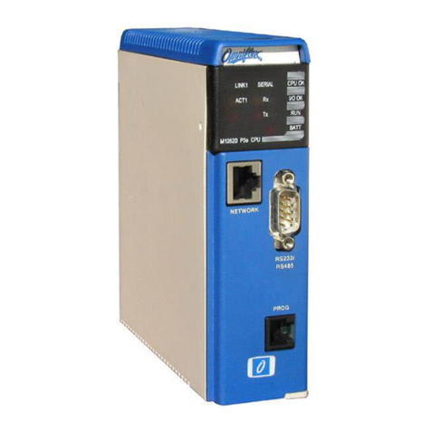
Figure 2.1: View of the M1267B P3e-R Redundant Controller CPU with 10/100 Ethernet
2.1 Front Panel LED Indicators:
The following table identifies which CPU’s have which LED Indicators. A full description of the
function of each indicator is given in section 4.10
NAME
COLOUR
M1260E
P3
M1261E
P3c
M1262F
P3e
M1267B
P3e-R
CPU OK
Green
Y
Y
Y
Y
I/O OK
Green
Y
Y
Y
Y
RUN
Green
Y
Y
Y
Y
BATT
Red
Y
Y
Y
Y
SERIAL Rx
Green
Y
Y
Y
Y
SERIAL Tx
Red
Y
Y
Y
Y
NETWORK Rx
Yellow
Y
NETWORK Tx
Red
Y
NETWORK TOKEN
Green
Y
NET LINK
Green
Y
Y
NET 100
Yellow
Y
Y
SYNC LINK
Green
Y
SYNC 100
Yellow
Y
Table 2.1: Front Panel LED Indicators
10/100 Ethernet Network Port
(not available on all CPU models)
Sync Link Port
(only available on
Redundant CPU’s
RS232/485 Serial Port
Programming Port

Maxiflex P3 PAC User Manual
16
-© Omniflex
UMM126XR18.pdf
2.2 Communication Ports
The following table shows the communications ports available on this range of CPUs.
Model
Description
Prog
Serial
Conet/c
Ethernet
Sync
M1260F
P3
Y
Y
M1261F
P3c
Y
Y
Y
M1262G
P3e
Y
Y
Y
M1264A
A3e
Y
Y
M1265B
A3e
Y
Y
Y
M1267C
P3e-R
Y
Y
Y
Y
2.2.1 Programming Port
The programming port is an RS232 port that implements the Conet/s protocol. This port is
used for software configuration, interrogation and program downloads using a Microsoft
Windows compatible PC, Laptop or Handheld computer. This port is compatible with the
Omniset configuration utility, and the Omniflex ISaGraf Programmer’s Workbench.
2.2.2 Serial Port
All P3 CPU’s are equipped with a serial port that can be used to connect to other serial
devices. Connection can be either RS232 or RS485.
The serial port can be configured for one of two protocols:
a) Modbus Slave protocol (ASCII or RTU) is available on this port allowing easy connection
to other third party products such as DCS or SCADA systems.
b) Modbus Master protocol (ASCII or RTU) is available on this port allowing easy connection
to third party Modbus Slave devices.
c) Conet/s protocol (peer-to-peer) is available on this port for integration into Conet
Intranets. Conet/s connection allows seamless network connection between devices with
full network capability such as report-by-exception, time-stamped event streams and
remote programming. The full-duplex nature of the Conet/s protocol makes efficient use
of the serial channel. With the use of modems or other virtual circuits, efficient wide area
networks can be easily constructed.
2.2.3 Conet/c Network Port
This port provides connection to a Conet/c industrial network. Conet/c is a true peer-to-peer
local area network (LAN) that allows reliable data transfer between multiple nodes over long
distances (up to 10km) using conventional twisted pair cabling found in most industrial plants.
2.2.4 Ethernet Network Port
This port provides connection to a 10/100 Ethernet network via a UTP connector on the front
of the module. The Ethernet port supports two protocols running under the TCP/IP transport
protocol:
•Modbus/TCP (Slave and Master)
•Conet/e (providing full support for all Conet features over Ethernet including remote
programming, and time-stamping at source)
These two protocols can co-exist on the Ethernet link

Maxiflex P3 PAC User Manual
17
-© Omniflex
UMM126XR18.pdf
2.2.5 Sync Link Port
This port provides connection to the other CPU in dual redundant applications. Use Link
Cable M1812A to connect the Primary and Secondary CPU’s via this port.
2.3 I/O Module support
The Maxiflex P3 CPU’s can interface to both local and remote I/O. One local Maxiflex Rack
and seven Remote I/O Racks can be supported to directly access a total of up to 3808 I/O
points (based upon 32 channel I/O modules) on a single CPU.
Initially P3 CPU’s supported three remote racks. This was upgraded to allow up to seven
remote racks. The earliest versions that support seven remote racks are show in the table
below:
Model
Description
Firmware Supporting Seven Remote Racks
M1260E
P3
V12.40 and above
M1261E
P3c
V12.40 and above
M1262F
P3e
V12.29 and above
M1264A
A3e
V12.40 and above
M1265B
A3e
V12.40 and above
M1267B
P3e-R
V12.40 and above
2.4 Dual Redundant Operation
The P3e-R CPU is designed to operate in dual redundant configuration. In this configuration
each CPU must be mounted on its own local Master Base with its own Power Supply.
I/O Modules may be fitted to these local Bases, but these I/O modules will only be directly
accessible by the CPU on this base.
If shared I/O modules are required, then remote Racks I/O must be used.
2.5 CPU Functions
The P3 CPU contains the following functions:
2.5.1 Real-Time Clock
These CPU’s have a real-time clock as a standard function. This clock has the following
features:
Battery-backed to retain real time while power is off for up to 5 years.
Resolution to 10 milliseconds
Current Time available in the Data Interchange Table
Last Power Up Time available in the Data Interchange Table
Last Power Down Time available in the Data Interchange Table
2.5.2 I/O Scanning
This function is responsible for the automatically scanning of conventional I/O modules
(IOM’s) installed on the Maxiflex base, reading input data and placing it in the DIT, and
writing data from the DIT to the output modules.

Maxiflex P3 PAC User Manual
18
-© Omniflex
UMM126XR18.pdf
If a User program is running in the CPU, then the I/O scanning is synchronised with this
User Program. If there is no User Program running, then the I/O is scanned every 10
milliseconds.
This I/O scanning therefore occurs whether there is a User Program running in the CPU
or not, allowing data acquisition or remote I/O applications to be implemented without
the need to write a User Program for the CPU. This feature significantly reduces system
engineering time.
2.5.3 I/O Module Management
This function is responsible for continuously monitoring all slots of the Maxiflex I/O
base, keeping track of the currently installed module types. This function also maintains
a copy of any I/O module configuration in the CPU, allowing I/O modules to be changed
without the need to reconfigure them.
2.5.4 Subscription Service
Central to many applications involving communications across networks is the need to
replicate data between nodes on the network. This feature provides an easy to use but
powerful data replication service between DIT’s in the system, whether they are local or
remote. This service provides change-of-state detection and error reporting for optimum
performance and reliability.
2.5.5 Queue Service
The P3 CPU has the ability to queue time stamped events that can be generated by
modules like the M1760/1 32SOE module or by user programs written specially for the
purpose. Once stored in the queue, PC based clients such as the Omniflex Conet OPC
Server are able to poll this queue over the network and extract the queued events for
analysis. It is also possible for a user application to extract queued events and perform
application specific processing such as converting the events to text strings and then
send these strings to a printer connected to the serial port.
Typical uses for the Queue Service are Sequence of Event monitoring applications
where the P3 provides a buffered interface between real time events detected at the
front end (using M1760/1 32SOE modules) and the Conet OPC Server at the backend.
2.5.6 Conet Routing Service
Many systems are constructed of multiple networks to overcome the difficulties of
topology or communication protocol conversion. The Routing service provides a means
to seamlessly interconnect these networks into an integrated intranet so that any node
in the system may be globally addressed from any other with no regard for its physical
location.
The P3 CPU can act as a router in these systems, automatically routing data packets
seamlessly between nodes on different networks.
2.5.7 Modbus Master Driver
The P3 CPU comes standard with a Modbus Master Driver that allows the CPU to
connect to any third party Modbus Slave device. This driver will operate over the
RS232/485 serial port that is available on all models of CPU, as well as over the
Ethernet port (using Modbus/TCP) of the M1262x and M1267x models.
A combined set of up to 32 queries can be configured for the CPU as a system. There
is no fixed allocation of queries per communications port where it is relevant.

Maxiflex P3 PAC User Manual
19
-© Omniflex
UMM126XR18.pdf
2.5.8 IEC61131 User Programming
The P3 CPU’s are programmable in all five IEC61131-3 programming languages.
Applications range from simple data scaling to analogue control systems and
programmable logic control.
The user program has access to the following features in the CPU:
Direct access to I/O modules in the system through the program I/O
Direct access to all Data Interchange Tables in the system.
Remotely programmable through any of the ports configured for the Conet protocol.

Maxiflex P3 PAC User Manual
20
-© Omniflex
UMM126XR18.pdf
3. CPU’s and the MAXIFLEX Architecture
This section explains the general architecture of the Maxiflex system. More specific details relating
to the configuration of the P3 CPU’s can be found in later Chapters.
3.1 General System Architecture
A diagram of the general MAXIFLEX System Architecture is shown in Figure 3.1
This diagram shows the P3 CPU in a system with an Intelligent Module (in this case a
Programmable Network Interface Module (NIM)) and a conventional I/O Module (IOM). NIM’s
and IOM’s can be arranged in any order in the available I/O Module slots of the system.
3.1.1 Maxiflex Bases
Two types of Maxiflex Base are available –Master Bases and Expander Bases. Both
Master and Expander Bases are available in a range of sizes (number of I/O Modules).
The P3 CPU must be mounted into the CPU Slot of a Master Base. Every Master Base
also requires a Power Supply (PSU) Module mounted into the dedicated PSU Slot.
One Expander Base can be connected to a Master Base giving a maximum of 15 local
I/O modules supported by a single P3 CPU.
Larger Expander Bases require an additional power supply to support the added I/O
Module load.
3.1.2 I/O Modules
The Maxiflex system supports a wide range of conventional Input/Output modules
(IOM’s). Some of these modules require configuration. This configuration is done in the
CPU, and the configuration is stored in the CPU.
The CPU manages the configuration of all IOM’s. If an IOM is exchanged, then the
CPU reconfigures the replacement module automatically. No additional user
intervention is required to replace an IOM.
3.1.3 Data Interchange Table (DIT) Overview
Data Interchange Tables (DIT) are the “crossroads” for data in the Maxiflex system. A
DIT is an array of 16 bit registers accessible from any function or communications port
in the system.
The P3 CPU has a DIT in which all the configuration settings and dynamic data,
including I/O can be accessed. Any exchange of data between functions in the CPU
and with the outside world takes place through the CPU’s DIT.
Intelligent I/O Modules also each have a DIT. A portion of the intelligent I/O modules’
DIT Registers are overlaid on to the CPU DIT, and appear as if they are part of the
CPU’s DIT. This extended DIT addressing is used to directly access data in any
intelligent modules such as Network Interface modules (NIM’s) installed on the Maxiflex
base as if the data is in the CPU.
A full explanation and layout of the DIT is given in Section 6
3.1.4 Intelligent Modules
Intelligent Modules are more than just I/O modules. Intelligent modules can be
considered as an extension of the CPU with their own “co-processors”.
Every Intelligent module also has its own Data Interchange Table (DIT). The size of this
DIT depends upon the type of intelligent module, but the lowest 2000 registers of this
This manual suits for next models
5
Table of contents
Other Omniflex Computer Hardware manuals
Popular Computer Hardware manuals by other brands

NETGEAR
NETGEAR WAG511 - 802.11a/b/g Dual Band Wireless PC... Specifications

Intel
Intel Itanium 2 Processor datasheet

Abocom
Abocom 10/100/Gigabit CardBus PC Card FG2003 Specification sheet

Omega Engineering
Omega Engineering OMG-PCI-DIO48 user guide

GNS
GNS 5894TAC quick guide

Applied Engineering
Applied Engineering RamWorks 2 MEG Plus installation guide