manuals.online logo
Brands
  1. Home
  2. •
  3. Brands
  4. •
  5. Omniflex
  6. •
  7. Computer Hardware
  8. •
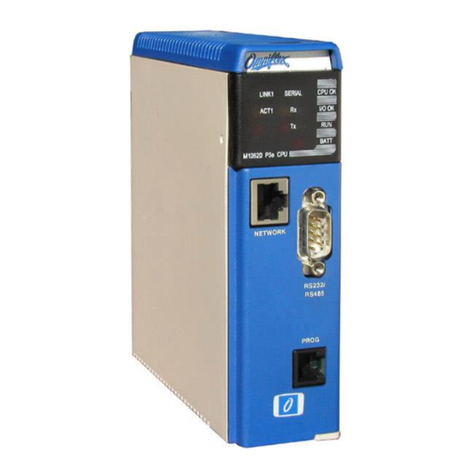
  9. Omniflex Maxiflex P3e-R M1267C User manual

Omniflex Maxiflex P3e-R M1267C User manual

M1267B Revised 06.11.06 Ver. 2 Data subject to change without notice © Copyright OMNIFLEX
IGM1267CR02 Part Number 8.0101.049
I N S T A L L A T I O N G U I D E
Maxiflex P3e-R CPU
M1267C
Introduction
This Installation Guide is intended to aid the fitment of the M1267 CPU in the field. For
operating details of this product, refer to the Users’ Manual. Please read this Installation Guide
first before installing this unit.
The Maxiflex P3e-R CPU is designed specifically for applications requiring PLC programming,
offering industry standard IEC61131 programming capabilities combined with powerful
industrial network communications features in a redundant configuration when paired with
another M1267B P3e-R CPU.
It is always fitted into the CPU slot of a Maxiflex master base, next to the PSU module. See
figure 1. It has one port which is a configurable serial port. This port has a DIP switch for
address and parameter settings. The M1267B is equipped with an Ethernet based Network
port for Supervisory communications, an additional Ethernet based Sync port for data
synchronisation with the paired M1267B CPU, and serial port (RS232/485) and a
programming port.
RAM is battery backed so that application program variables are not lost on power down, the
battery will be connected if you have an Omniflex application loaded already. If you are
starting with a fresh CPU from stock the battery will need to be connected.
Figure 1 : Module Positions
Hardware Installation Procedure
1. If the BATTERY is required then connect jumper located in the front of the module, just
above the DB-9 serial port connector. Remove paper strip which says PULL TO
CONNECT BATTERY. The Real time clock must then be set.
M1267B Revised 06.11.06 Ver. 2 Data subject to change without notice © Copyright OMNIFLEX
IGM1267CR02 Part Number 8.0101.049
2. If the CPU is going to be programmed use Programming port cable M1831 which is
available as an accessory (Model No. M1831).
3. Plug the CPU into the CPU slot (as per Figure 1).
Software Requirements
Omniset is the PC utility that is used to configure the unit.
Configuring the Realtime Clock(RTC)
1. Assemble the Maxiflex base as shown in Figure 1 with the M1267B fitted into the CPU slot
and a suitable Maxiflex PSU in the PSU slot
2. Connect power to your system.
3. Connect the M1831 programming cable between the COM port of your PC/laptop and the
programming port of the Maxiflex CPU.
4. Open Omniset and click on File->Connect->Maxiflex CPU TAB.
Select the GROUP Configuration->Ports->Realtime Data->Date/Time which is found in the left
hand pane. Change the RTC settings by pointing the mouse to the ITEM you wish to change
and clicking on the right mouse button and selecting the New Value option that pops up. Enter
you new setting when prompted. Refer to screen grab below.
Table 1: P3e CPU Front Panel Diagnostics
LED Legend
LED Colour
Description
CPU OK
Green
ON - CPU is healthy
OFF or Flashing –No power applied or CPU Faulty
I/O OK
Green
ON - I/O Module status healthy and I/O Manifest is
configured.
FLASHING –I/O Manifest is configured but
disagrees with installed hardware.
OFF –I/O Manifest is not configured.
RUN
Green
ON –user application software is running
OFF –No user application software is running
Flashing –Terminal interaction with CPU
BATT
RED
ON –Internal battery is LOW or not connected.
OFF –Internal battery is good.
SERIAL Rx
YELLOW
ON –data is being received on serial port
OFF –serial port receiver is idle
M1267B Revised 06.11.06 Ver. 2 Data subject to change without notice © Copyright OMNIFLEX
IGM1267CR02 Part Number 8.0101.049
81 2 3 4 5 6 7
ON
81 2 3 4 5 6 7
ON
SERIAL Tx
RED
ON –serial data is being transmitted on serial port
OFF –serial port transmitter is idle
NET LINK
GREEN
ON –Ethernet Network link established, blinking with
Ethernet network communications.
OFF –No Ethernet Link present.
NET 100
YELOW
ON –100 BaseT Ethernet interface.
OFF –10 BaseT Ethernet interface.
SYNC LINK
GREEN
ON –Sync link established, blinking with sync link
communications.
OFF –No Sync Link present.
SYNC 100
YELOW
ON –100 BaseT Ethernet interface.
OFF –10 BaseT Ethernet interface.
Table 2: Programming Port Pinout
Signal Name
DB-9
FCC-68 Pin No.
Rx Data from P3
2
4
Tx Data to P3
3
1
Ground Reference
5
2
All other pins are reserved and must not be connected.
NOTE: This information is only necessary if you are making up your own programming cable.
If you are using a M1831 Programming port cable, simply connect the programming cable
between the CPU and PC as per the connectors of the programming cable.
Table 3: Switch 1 Set-up (Serial Port)
Communications Protocol
Serial Port Dipswitch setting
Modbus Protocol (Slave device):
Transmission Mode: ASCII
Baud rate: 9600
Data bits: 7
Parity: none
Stop bits: 1
Address: see dipswitch
Switches 1-5: Modbus ID
Switches 6-8: Protocol
Switch 8 ON = Modbus default
Conet/s Protocol
Transmission Mode: RTU
Baud rate: 19200
Data bits: 8
Parity: none
Stop bits: 1
Address: see dipswitch
Switches 1-5: Conet ID
Switches 6-8: Protocol
Switch 7 ON = Conet/s default
The default operation is to use the serial port for standard communications allowing the user to
get the CPU up and running quickly and easily both on the test bench and in the field. In this
case the Serial Port Dipswitch beneath the male, sub-miniature DB-9 connector has the above
default configurations. The serial port is also software configurable using the Omniset utility or
application program, but when switch 7or 8 of the dipswitch is turned ON, then the dipswitch
M1267B Revised 06.11.06 Ver. 2 Data subject to change without notice © Copyright OMNIFLEX
IGM1267CR02 Part Number 8.0101.049
setting overrides the software configuration. To restore the settings to the software
configuration, simply set switch 7 or 8 of the dipswitch OFF.
Table 4: Serial Port Pinout
The M1267B P3e CPU allows jumperless conversion between RS232 and RS485
communications. By simply following the appropriate pinout of the serial port connector below
it is possible to connect the CPU in either mode without making any hardware or software
changes to the CPU.
Pin
number
Communication Standard
RS232
RS485
1
Do not connect
Rx Data + (In)
2
Rx Data (In)
Rx Data –(In)
3
Tx Data (Out)
Do not connect
4
Do not connect
Tx Data+ (Out)
5
Ground
Ground
6
Do not connect
Vcc
7
RTS (Out)
Do not connect
8
CTS (In)
Do not connect
9
Do not connect
Tx Data –(Out)
Serial Port Default Settings
1. The default Protocol is Conet/s.
1. The default Baud Rate is 19200.
2. The default Data Bits is 8.
3. The default Parity is None.
4. The default Stop bits is 1 Stop Bit.
5. The default DTR/CTS Handshaking is Off.
6. The default DTR/CTS Timeout (ms) is 0.
Changing Serial Port Settings
1. Assemble the Maxiflex base as shown in Figure 1 with the M1267B fitted into the CPU slot
and a suitable Maxiflex PSU in the PSU slot
2. Connect power to your system.
3. Connect the M1831 programming cable between the COM port of your PC/laptop and the
programming port of the Maxiflex CPU.
4. Open Omniset and click on File->Connect->Maxiflex CPU TAB.
Select the GROUP Configuration->Ports->Serial Port which is found in the left hand pane.
Change your Serial Port settings by pointing the mouse to the ITEM you wish to change and
clicking on the right mouse button and selecting the New Value option that pops up. Enter you
new setting when prompted. Refer to screen grab below.
M1267B Revised 06.11.06 Ver. 2 Data subject to change without notice © Copyright OMNIFLEX
IGM1267CR02 Part Number 8.0101.049
Network Port
Network Port Default Settings
NOTE: These settings refer to the Network port of the CPU and is not to be confused with the
Sync port. Below is a list of
5. The default IP Address is 192.168.0.100.
6. The default Subnet Mask is 255.255.255.0
7. The default Gateway Address is 0.0.0.0
8. The default Modbus TCP Port Number is 502, this must not be changed.
9. The default Conet/e Port Number is 1300, this must not be changed.
10.The default Local ID is 2.
Changing Ethernet Settings
11.Assemble the Maxiflex base as shown in Figure 1 with the M1267B fitted into the CPU slot
and a suitable Maxiflex PSU in the PSU slot
12.Connect power to your system.
13.Connect the M1831 programming cable between the COM port of your PC/laptop and the
programming port of the Maxiflex CPU.
14.Open Omniset and click on File->Connect->Maxiflex CPU TAB.
15.Select the GROUP Configuration->Ports->Ethernet Port which is found in the left hand
pane. Change your Ethernet settings by pointing the mouse to the ITEM you wish to
change and clicking on the right mouse button and selecting the New Value option that
pops up. Enter you new setting when prompted. Refer to screen grab below.
M1267B Revised 06.11.06 Ver. 2 Data subject to change without notice © Copyright OMNIFLEX
IGM1267CR02 Part Number 8.0101.049

Other Omniflex Computer Hardware manuals

Omniflex Maxiflex P3 User manual

Omniflex

Omniflex Maxiflex P3 User manual

Omniflex Maxiflex P3 CPU User manual

Omniflex

Omniflex Maxiflex P3 CPU User manual

Omniflex Maxiflex P3 M1260E User manual

Omniflex

Omniflex Maxiflex P3 M1260E User manual

Omniflex M1261F User manual

Omniflex

Omniflex M1261F User manual

Popular Computer Hardware manuals by other brands

Corsair H80i v2 quick start guide

Corsair

Corsair H80i v2 quick start guide

Corsair A50 Mounting guide

Corsair

Corsair A50 Mounting guide

Multitech ISI551PC owner's manual

Multitech

Multitech ISI551PC owner's manual

InWin PF Series user manual

InWin

InWin PF Series user manual

A4Tech RG-30 user manual

A4Tech

A4Tech RG-30 user manual

Micromega AP-180 operating manual

Micromega

Micromega AP-180 operating manual

foc.us CS-1 Specifications

foc.us

foc.us CS-1 Specifications

T L Audio Ebony A3 user manual

T L Audio

T L Audio Ebony A3 user manual

Contec Flexlan PC Card FX-DS-110 user guide

Contec

Contec Flexlan PC Card FX-DS-110 user guide

ARTESYN EMBEDDED TECHNOLOGIES ATCA-9405 Installation and use

ARTESYN EMBEDDED TECHNOLOGIES

ARTESYN EMBEDDED TECHNOLOGIES ATCA-9405 Installation and use

Oki Semiconductor VoiceKit2000 instruction manual

Oki

Oki Semiconductor VoiceKit2000 instruction manual

Corsair XC7 RGB manual

Corsair

Corsair XC7 RGB manual

Blue Technix CM-i.MX27-C-C-Q26S128F32N512 Hardware user manual

Blue Technix

Blue Technix CM-i.MX27-C-C-Q26S128F32N512 Hardware user manual

ARTESYN EMBEDDED TECHNOLOGIES SharpMedia PCIE-8120 Assembly, Installation and Use

ARTESYN EMBEDDED TECHNOLOGIES

ARTESYN EMBEDDED TECHNOLOGIES SharpMedia PCIE-8120 Assembly, Installation and Use

A4Tech RN-10 user manual

A4Tech

A4Tech RN-10 user manual

Multitech MT5600SMI brochure

Multitech

Multitech MT5600SMI brochure

Corsair AF RGB ELITE manual

Corsair

Corsair AF RGB ELITE manual

ELAN DIGITAL SYSTEMS AD135 user guide

ELAN DIGITAL SYSTEMS

ELAN DIGITAL SYSTEMS AD135 user guide

manuals.online logo
manuals.online logoBrands
  • About & Mission
  • Contact us
  • Privacy Policy
  • Terms and Conditions

Copyright 2025 Manuals.Online. All Rights Reserved.