Page 9
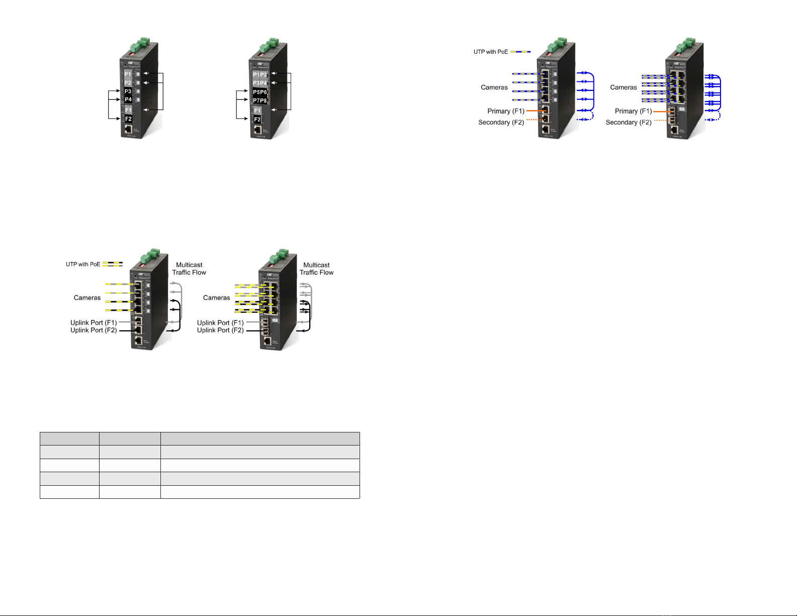
Dual Device Mode
When models with 4 RJ-45 user ports are congured for Dual Device Mode and
Directed Switch Mode, the trafc from ports P1 and P2 is only forwarded to uplink
port F1 and ports P3 and P4 are only forwarded to uplink port F2. When models with
8 RJ-45 user ports are congured for Dual Device Mode and Directed Switch Mode,
the trafc from ports P1 - P4 is only forwarded to uplink port F1 and ports P5 - P8
are only forwarded to uplink port F2. This prevents broadcast trafc from ooding
other network ports. Incoming trafc from F1 and F2 follows MAC address mapping.
Dual Device with Directed Switch Mode
SW3 and SW4: Uplink Redundancy
Uplink redundancy mode is only supported on models with two uplink ports.
The modes are described with MAC learning enabled. When MAC learning is
disabled, the module will send data to all ports.
SW3 SW4 Function
LEFT LEFT Switch Mode (factory default)
LEFT RIGHT Switch Mode (factory default)
RIGHT LEFT Redundant Mode - no return to primary (F1)
RIGHT RIGHT Redundant Mode - return to primary (F1)
Uplink Redundancy
When congured for Uplink Redundant Mode “no return to primary”, the uplink
ports operate as redundant links. A fault on the primary Port F1, will cause a fail
over to the secondary Port F2 within 50msec. Port F1 will become the secondary
port once the failure condition has been restored because “no return to primary”
has been selected.
Page 10
Redundant Uplink
When congured for Uplink Redundant Mode “return to primary’, a fault on the
primary Port F1, will cause a fail over to the secondary Port F2 within 50msec.
The module will return to the primary Port F1 after the failure condition has been
restored for 6 seconds.
SW5: MAC Learning - “MAC Learning/Off”
When this DIP-switch is in the LEFT “MAC Learning” position (factory default), all
ports on the module will learn the source MAC address of each received packet and
store the address so packets destined for the stored addresses can be forwarded
to the appropriate port on the module. When the DIP-switch is in the RIGHT “Off”
position, learning is turned off and all received unicast packets are forwarded to
all ports.
SW6: Pause - “Pause Off/On”
Setting the DIP-switch to the LEFT “Pause Off” position (factory default) congures
the module to advertise no Pause capability on all ports. Setting this DIP-switch
to the RIGHT “On” position congures the module to advertise Symmetrical and
Asymmetrical Pause capability to all ports.
SW7: L2CP - “L2CP Tunnel/Discard”
When this DIP-switch is in the LEFT “L2CP Tunnel” position (factory default), all
L2CP frames will be tunneled through the module. When this DIP-switch is in the
RIGHT “Discard” position, all L2CP frames will be discarded.
SW8: PSE Reset - “Off/PoE Reset”
The module can be congured to disable (reset) the PoE output power for 5 seconds
after a loss of receive link on any uplink port. This feature is typically used to allow
a PD to re-initialize after a failure on the incoming uplink.
When this DIP-switch is in the LEFT “Off” position (factory default), PoE output power
does not reset on a loss of receive link on any uplink port. When this DIP-switch is
in the RIGHT “PoE Reset” position, the module will disable PoE output power for 5
seconds following a loss of receive link on any uplink port.
When uplink redundancy is enabled, the loss of link on either F1 or F2 will not cause
the PD to be re-initialized even though the PSE Reset is enabled. The PD will be
re-initialized on a loss of receive link on both uplink ports.
When Dual Device Mode is enabled, the loss of receive link on a uplink port will
re-initialize the PDs associated with that uplink port. On models with 4 RJ-45 user