manuals.online logo
Brands
  1. Home
  2. •
  3. Brands
  4. •
  5. Omnitron Systems
  6. •
  7. Switch
  8. •
  9. Omnitron Systems FlexSwitch 6550-FK User manual

Omnitron Systems FlexSwitch 6550-FK User manual

FlexSwitchTM 1Fx+4U Model 6550-FK Replacement Kit
User Manual
PRODUCT OVERVIEW
The 6550-FK is the direct replacement for the discontinued FlexSwitch Model 600XC 1Fx + 4U.
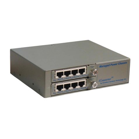
The 6550-FK replacement kit consists of one iConverter 10/100BASE-Tx to 100BASE-Fx
Media Converter Module and one iConverter 4Tx Switch Module installed in a iConverter
2-Module Chassis.
The 6550-FK provides auto-negotiating 10/100 RJ-45 ports with auto-crossover that enables
easy attachment to hubs, switches and workstations. The 100BASE-Fx ber port supports
half or full duplex operation.
The 6550-FK features on-board and front panel accessible DIP-Switches for manual
conguration of the ports.
Chassis Models
FlexSwitch Replacement Matrix
Disconnected
Part
Replacement Part
Connector Type Fiber Type Distance
SC ST
6550-0 6550-0-FK - MM 5km
6550-2 6550-2-FK - SM 30km
6550-3 6550-3-FK - SM 60km
6551-0 - 6551-0-FK MM 5km
6551-2 - 6551-2-FK SM 30km
INSTALLATION PROCEDURE
1) Congure DIP-Switches
2) Install Module in Chassis and Connect Cables
3) Installing the Chassis
4) Apply AC Power
5) Verify Operation
Page 1
1) Congure DIP-Switches
The 6550-FK has been pre-congured with Auto-Negotiation enabled on all RJ-45 ports for
plug and play easy of use. However, the iConverter Modules offer additional conguration
exibility.
4 Port Switch Module
Each 4-Port Switch Module has been pre-congured for Auto-Negotiation with Backplane
A and B Enabled.
4 Port Switch Module Default DIP-Switch Settings
Backplane Port A Enable/Disable
This DIP-Switch must be in the LEFT “Enable” position for the module to operate correctly.
The switch provides backplane connectivity with the other switch module.
Backplane Port B Enable/Disable
This DIP-Switch must be in the LEFT “Enable” position for the module to operate correctly.
The switch provides backplane connectivity with the other switch module.
Port 1 and Port 2 RJ-45 Auto-Negotiate/Manual
When this DIP-Switch is in the RIGHT “AN” position, the Port automatically determines the
speed and duplex mode of the connecting copper device. If the connecting device cannot
provide the proper signal to indicate its own mode of operation, this DIP-Switch should be
set to the LEFT “Man” position. Manual mode requires manually conguring the RJ-45 port
to match the speed and the duplex mode of the connecting device using the Speed and
Duplex DIP-Switches.
When a port is congured for Auto-Negotiation, the automatic crossover detection is enabled
for that particular port. Automatic crossover detection is disabled when the port is congured
for manual negotiation.
Port 1 and Port 2 Speed 10/100Mbps
When the port is congured for Manual Mode (SW3/SW6 in the LEFT position), the Speed
DIP-Switch determines the speed of operation for the designated port. Setting the Speed
DIP-Switch to the RIGHT “100” position forces the port to operate at 100Mbps. Setting this
DIP-Switch to LEFT “10” position forces the port to operate at 10Mbps. Adjust the Speed
DIP-Switch to match the speed of the connecting device.
Port 1 and Port 2 Duplex Full/Half-Duplex
When the port is congured for Manual Mode (SW3/SW6 in the LEFT position), the Duplex
DIP-Switch determines the duplex operation mode for the port. Setting the Duplex DIP-
Switch to the RIGHT “FD” position forces the port to operate in Full-Duplex. Setting this
Page 2
Page 3
DIP-Switch to the LEFT “HD” position forces the port to operate in Half-Duplex. Adjust the
Duplex DIP-Switch to match duplex mode the connecting UTP device.
When a port is congured for Auto-Negotiation, the Duplex DIP-Switch will determine if the port
advertises Full-Duplex or Half-Duplex. When the Duplex DIP-Switch is in the “FD” position,
the port advertises Full-Duplex and Half-Duplex capability. When in the Duplex DIP-Switch
is in the “HDX” position, the port advertises only in Half-Duplex capability.
Fiber Module - Front Panel
The modules have been pre-congured as illustrated below. Using the front panel DIP-
Switches, the module can be recongured for customer-specic applications.
Fiber Module Front Panel Default DIP-Switch Settings
Fiber Full/Half-Duplex
When in the Fiber Full/Half-Duplex DIP-Switch is in the “FDX” position, the ber port operates
in Full-Duplex mode. When in the “HDX” position, the ber port operates in Half-Duplex
mode and its distance is limited by the IEEE 802.3 standard to 412 meters.
UTP Auto/Manual Negotiate
When the UTP “AN/Man” DIP-Switch is in the Auto-Negotiate “AN” position, the converter
Auto-Negotiates and matches the 10/100 speed and duplex mode of a mating Auto-Negotiating
device connected to its RJ-45 port.
When the UTP “AN/Man” DIP-Switch is in the “Man” position, the converter does not auto-
Negotiate and operates in the mode selected by the Full/Half Duplex “FDX/HDX” and “10/100”
DIP-Switches.
UTP 10/100
When the UTP “AN/Man” DIP-Switch is in the “Man” position, the UTP “10/100” DIP-Switch
selects the speed of the RJ-45 port. When in the “100” position (factory default), the RJ-45
port operates at 100 Mbps. When in the “10” position the RJ-45 port operates at 10 Mbps.
UTP Full/Half-Duplex
When the UTP “AN/Man” DIP-Switch is in the “Man” position, the “FDX/HDX” DIP-Switch
selects the duplex mode of the RJ-45 port. When in the “FDX” position, the RJ-45 port operates
in Full-Duplex mode. When in the “HDX” position, the RJ-45 port operates in Half-Duplex.
Set the duplex mode to match the connecting device and check for link status.
Note: Attaching the Auto-Negotiating RJ-45 port of the 6540-FK to a device with a manual/
forced /hard-coded RJ-45 port may result in an unpredictable port setting with excessive
collisions and poor link performance. When operating in Manual mode, both mating ports
MUST be set manually to the same speed and duplex mode.
On Board DIP-Switches
The modules have on-board DIP-Switches for the conguration of the Link Modes and
Backplane connectivity. For more information on Link Mode, see the Link Mode Application
Note.
The modules are pre-congured as illustrated below.
RFD
Down
4
3
2
1
BPOEN
LP
=
=
=
=
Remote Fault Detect Enable
Backplane Enable
Link Propagate/Link Segment
Not Used (Factory Set)
On-Board DIP-Switches Showing Factory Default Settings
Remote Fault Detection
When the Remote Fault Detect “RFD” DIP-Switch is in the UP position, the RFD mode is
selected. When in the DOWN position, the RFD mode is disabled.
Note: Connecting two converters with both set to RFD mode is an illegal setting and will
cause a “deadly embrace” lockup.
A and B Backplane Enable
This DIP-Switch must be in the UP position for the module to operate correctly. The backplane
must be enabled for the modules to communicate.
Link Propagate/Link Segment
When both the Link Propagate/Link Segment “LP” and the Remote Fault Detect “RFD”
DIP-Switches are in the DOWN position, Link Segment mode is enabled. When the Link
Propagate/Link Segment “LP” DIP-Switch is in the UP position, and the Remote Fault Detect
“RFD” DIP-Switch is in the DOWN position, Link Propagate mode is enabled.
Note: Setting both the “LP” and the “ RFD” to the UP positions on the same module is an
illegal mode that will result in unpredictable behavior.
2) Install Module in the Chassis and Connect the Cables
The modules are pre-installed in the 2-Module chassis with the backplane enabled on both
modules.
a. Carefully slide the module into an open slot in the chassis. Align the module with the
installation guides and ensure that the module is rmly seated against the backplane.
Secure the module by fastening the front panel thumbscrew (push in and turn clockwise
to tighten) to the chassis front. Verify the “Pwr” LED is ON (indicating the chassis is
powered).
b. Connect an appropriate multimode or single-mode ber cable to the ber port of the
installed modules. It is important to make sure that the transmit (TX) is attached to
the receive side of the device at the other end and the receive (RX) is attached to the
transmit side.
c. Connect the RJ-45 ports via a Category 5 cable to a 10BASE-T or 100BASE-Tx Ethernet
device.
Page 4
3) Installing the Chassis
Wall and Rack Mounting
The 2-Module chassis can be wall/rack mounted by attaching the optional wall/rack mount
brackets (8249-0). A 19” Rack Mount Shelf (8260-0) is available to install two 2-Module
chassis.
The operating temperature of this equipment is 0 to 50 degrees C. If installed in a closed
or multi-unit rack assembly, the operating ambient temperature of the rack must not exceed
the maximum rated temperature for the chassis used.
Installation of the equipment should be such that the air ow in the front and back of the unit
is not compromised or restricted.
Installing this equipment into a rack in such a way as to make it unstable may cause injury
or death. Always make sure that the rack you are installing this equipment into is properly
secured, stable, balanced and designed to carry the weight and weight distribution of this
equipment.
Never use this equipment to carry any weight except its own. Never use it as a shelf to
support the weight of other equipment.
4) Apply AC Power
Power source should be available within 5 ft. of the chassis and installed per the National
Electrical Code, ANSI/NFPA-70.
This equipment requires a 100-240VAC, 0.5Amp, 50/60Hz power outlet. Appropriate
overloading protection should be provided on the AC power source outlets utilized.
Appropriate overloading protection should be provided on all AC power source outlets utilized.
Attach the AC power cord to the back of the chassis. Connect the AC power cords to the AC
outlets and switch the outlets ON.
Any installed iConverter modules will illuminate the power LED.
NEVER ATTEMPT TO OPEN THE CHASSIS OR SERVICE THE
POWER SUPPLYORFAN MODULE. OPENING THE CHASSIS
MAY CAUSE SERIOUS INJURYOR DEATH.
THERE ARE NO USER REPLACEABLE OR SERVICEABLE
PARTS IN THIS UNIT.
WARNING!!!
Rear of 2-Module Chassis with Power Cord
Page 5
5) LED Indicators
Each module has LED indicators to provide connection information.
4 Port Switch Module
LED Function
“Legend” Color OFF ON
Power
“Pwr” Yellow No power Module has power
Port x
“100 Link” Green Not linked at 100Mbps ON: Linked at 100Mbps
Blinking: Data activity
Port x
“10 Link” Green Not linked at 10Mbps ON: Linked at 10Mbps
Blinking: Data activity
x = Port number (1 - 4)
Fiber Module
LED Function
“Legend” Color OFF ON
Power
“Pwr” Yellow No power Module has power
Port 1 Fiber
Duplex
“FDX”
Green Fiber in Half Duplex Fiber in Full Duplex
Port 1 Fiber
Link
“Lk/Act”
Green No ber link ON: Fiber linked
Blinking: Fiber activity
Port 2 RJ-45
Negotiation
“AN”
Green RJ-45 in Manual negotiation RJ-45 in Auto negotiation
Port 2 RJ-45
Speed
“100”
Green RJ-45 not linked at 100Mbps RJ-45 linked at 100Mbps
Port 2 RJ-45
Speed
“10”
Green RJ-45 not linked at 10Mbps RJ-45 linked at 10Mbps
Port 2 RJ-45
Duplex
“FDX”
Green RJ-45 in Half Duplex RJ-45 in Full Duplex
Port 2 RJ-45
Link
“Lk/Act”
Green No RJ-45 link ON: RJ-45 linked
Blinking: Data activity
LED Indicators
Page 6
Specications
Description Fast Ethernet Switch
with ve 10/100 RJ-45 Ports and one 100 Fiber Port
Standards IEEE 802.3
Regulatory
Compliances UL, CE, FCC Class A, UKCA
Environmental RoHS, WEEE, REACH
Frame Size 1,536 bytes
Port Type Copper:
Fiber:
10/100BASE-T (RJ-45)
100BASE-FX (ST, SC)
Cable Type Copper:
Fiber:
EIA/TIA 568A/B, Cat 5 UTP and higher
Multimode: 50/125µm, 62.5/125µm
Single-mode: 9/125µm
AC Power
Requirements
100 to 240VAC, 50/60Hz
0.5A @ 120VAC
Dimensions
W x D x H 6.7” x 5.51” x 1.87” (435.6 mm x 228.6 mm x 44.5 mm)
Weight 3.0 lbs. (1.36 kg)
Temperature Commercial: 0 to 50°C
Storage: -40 to 80°C
Humidity 5% to 95% non-condensing
Altitude -100m to 4,000m
Warranty Lifetime warranty with 24/7/365 free Technical Support
General and Copyright Notice
This publication is protected by U.S. and international copyright laws. All rights reserved. The whole or
any part of this publication may not be reproduced, stored in a retrieval system, translated, transcribed,
or transmitted, in any form, or by any means, manual, electric, electronic, electromagnetic, mechanical,
chemical, optical or otherwise, without prior explicit written permission of Omnitron Systems Technology,
Inc.
The following trademarks are owned by Omnitron Systems Technology, Inc.: FlexPointTM, FlexSwitchTM,
iConverter®, miConverterTM, NetOutlook®, OmniLight®, OmniConverter®, RuggedNet®, Omnitron Systems
Technology, Inc.TM, OSTTM and the Omnitron logo.
All other company or product names may be trademarks of their respective owners.
The information contained in this publication is subject to change without notice. Omnitron Systems
Technology, Inc. is not responsible for any inadvertent errors.
Warranty
This product is warranted to the original purchaser (Buyer) against defects in material and workmanship
for a period of two (2) years from the date of shipment. A lifetime warranty may be obtained by the original
purchaser by registering this product at www.omnitron-systems.com/support within ninety (90) days from
the date of shipment. During the warranty period, Omnitron will, at its option, repair or replace a product
which is proven to be defective with the same product or with a product with at least the same functionality.
For warranty service, the product must be sent to an Omnitron designated facility, at Buyer’s expense.
Omnitron will pay the shipping charge to return the product to Buyer’s designated US address using
Omnitron’s standard shipping method.
Page 7
Limitation of Warranty
The foregoing warranty shall not apply to product malfunctions resulting from improper or inadequate use
and/or maintenance of the equipment by Buyer, Buyer-supplied equipment, Buyer-supplied interfacing,
unauthorized modications or tampering with equipment (including removal of equipment cover by
personnel not specically authorized and certied by Omnitron), or misuse, or operating outside the
environmental specication of the product (including but not limited to voltage, ambient temperature,
radiation, unusual dust, etc.), or improper site preparation or maintenance.
No other warranty is expressed or implied. Omnitron specically disclaims the implied warranties of
merchantability and tness for any particular purpose.
The remedies provided herein are the Buyer’s sole and exclusive remedies. Omnitron shall not be liable
for any direct, indirect, special, incidental, or consequential damages, whether based on contract, tort,
or any legal theory.
Environmental Notices
The equipment covered by this manual must be disposed of or recycled in accordance with the Waste
Electrical and Electronic Equipment Directive (WEEE Directive) of the European Community directive
2012/19/EU on waste electrical and electronic equipment (WEEE) which, together with the RoHS
Directive 2015/863/EU, for electrical and electronic equipment sold in the EU after July 2019. Such
disposal must follow national legislation for IT and Telecommunication equipment in accordance with the
WEEE directive: (a) Do not dispose waste equipment with unsorted municipal and household waste. (b)
Collect equipment waste separately. (c) Return equipment using collection method agreed with Omnitron.
The equipment is marked with the WEEE symbol shown to indicate that it must be collected
separately from other types of waste. In case of small items the symbol may be printed only on the
packaging or in the user manual. If you have questions regarding the correct disposal of equipment go
to www.omniton-systems.com/support or e-mail to Omnitron at [email protected].
Safety Warnings and Cautions
ATTENTION: Observe precautions for handling electrostatic discharge sensitive devices.
WARNING: Potential damage to equipment and personal injury.
WARNING: Risk of electrical shock.
CUSTOMER SUPPORT INFORMATION
Phone: (949) 250-6510
Fax: (949) 250-6514
Address: Omnitron Systems Technology, Inc.
38 Tesla
Irvine, CA 92618, USA
Email: [email protected]
URL: www.omnitron-systems.com
040-06550-FK1B 10/22
Page 8
Other Omnitron Systems Switch manuals

Omnitron Systems RuggedNet 10G/Mi User manual

Omnitron Systems

Omnitron Systems RuggedNet 10G/Mi User manual

Omnitron Systems OmniConverter G/M User manual

Omnitron Systems

Omnitron Systems OmniConverter G/M User manual

Omnitron Systems RuggedNet GPoE+/Mi User manual

Omnitron Systems

Omnitron Systems RuggedNet GPoE+/Mi User manual

Omnitron Systems RuggedNet GHPoE/Si User manual

Omnitron Systems

Omnitron Systems RuggedNet GHPoE/Si User manual

Omnitron Systems OmniConverter 10G/Sx 6 User manual

Omnitron Systems

Omnitron Systems OmniConverter 10G/Sx 6 User manual

Omnitron Systems RuggedNet 10GPoEBT/Mi User manual

Omnitron Systems

Omnitron Systems RuggedNet 10GPoEBT/Mi User manual

Omnitron Systems FlexSwitch 6700-FK User manual

Omnitron Systems

Omnitron Systems FlexSwitch 6700-FK User manual

Omnitron Systems RuggedNet 10GPoEBT/Si User manual

Omnitron Systems

Omnitron Systems RuggedNet 10GPoEBT/Si User manual

Omnitron Systems RuggedNet 10GPoE+/Mi User manual

Omnitron Systems

Omnitron Systems RuggedNet 10GPoE+/Mi User manual

Popular Switch manuals by other brands

D-Link DES-1050G Quick installation guide

D-Link

D-Link DES-1050G Quick installation guide

Zamel WZM-01 instruction manual

Zamel

Zamel WZM-01 instruction manual

Elko CRM-42 manual

Elko

Elko CRM-42 manual

Pakedge Device & Software SE-8P user manual

Pakedge Device & Software

Pakedge Device & Software SE-8P user manual

3Com Switch 4500 Family Getting started guide

3Com

3Com Switch 4500 Family Getting started guide

Basalte CHOPIN KNX installation manual

Basalte

Basalte CHOPIN KNX installation manual

Cabletron Systems ESXMIM Management guide

Cabletron Systems

Cabletron Systems ESXMIM Management guide

INSTEON Mini Remote 2342-242 owner's manual

INSTEON

INSTEON Mini Remote 2342-242 owner's manual

Belkin F1DF102P user guide

Belkin

Belkin F1DF102P user guide

ATEN CS-62B user manual

ATEN

ATEN CS-62B user manual

Altronix NetWay Series installation guide

Altronix

Altronix NetWay Series installation guide

Plantronics MDA524 QD user guide

Plantronics

Plantronics MDA524 QD user guide

Accton Technology Fast EtherHub 3500 Series Installation and user guide

Accton Technology

Accton Technology Fast EtherHub 3500 Series Installation and user guide

LevelOne FEP-0311 user manual

LevelOne

LevelOne FEP-0311 user manual

Altusen KH1508Ai user manual

Altusen

Altusen KH1508Ai user manual

DeviceWell HDS9106 user manual

DeviceWell

DeviceWell HDS9106 user manual

steute RF 96 ST SW868 Vcc extern Mounting and wiring instructions

steute

steute RF 96 ST SW868 Vcc extern Mounting and wiring instructions

gofanco Switcher5p user guide

gofanco

gofanco Switcher5p user guide

manuals.online logo
manuals.online logoBrands
  • About & Mission
  • Contact us
  • Privacy Policy
  • Terms and Conditions

Copyright 2025 Manuals.Online. All Rights Reserved.