Contents 1. Introduction
CONTENTS, INTRODUCTION, FEATURES AND SAFETY PRECAUTIONS
WyreStorm NetworkHD and NetworkHD-PRO systems
enable HDMI distribution over IP network switches. The
NHD-IP-CTL is the central system controller that will
automatically discover NetworkHD & NetworkHD-PRO
components on the same network. It allows all system
components to be congured from a single web interface
to dramatically reduce conguration times.
The NHD-IP-CTL also enables WyreStorm NetworkHD and
NetworkHD-Pro systems to interface with third party control
systems, enabling them to control WyreStorm’s powerful matrix
switching and video wall functionality.
For further information on this product and other WyreStorm
ranges, visit our website or download our latest product guide.
www.wyrestorm.com
• Full Telnet API
• Automatic detection of TX/RX system components
using ‘Bonjour’ technology
• Matrix switching control
• Video Wall Control
• HTTP, TCP/IP, Multicast & Bonjour
WyreStorm reserves the right to change hardware,
software, packaging and any accompanying
documentation without prior written notice.
1. Do not expose this apparatus to rain, moisture,
sprays, drips or splashes and ensure that no
objects containing liquids are placed on the
apparatus, including cups, glasses and vases.
2. Do not place this unit in a conned space such as
enclosed shelving, cabinets or bookshelves.
Ensure the unit is adequately ventilated.
3. To prevent the risk of electric shock or re hazard
due to overheating, do not cover the unit or
obstruct ventilation openings with material,
2. Features
Introduction
Features
Safety Precautions
Package Contents
Panel Display:
i. Front
ii. Rear
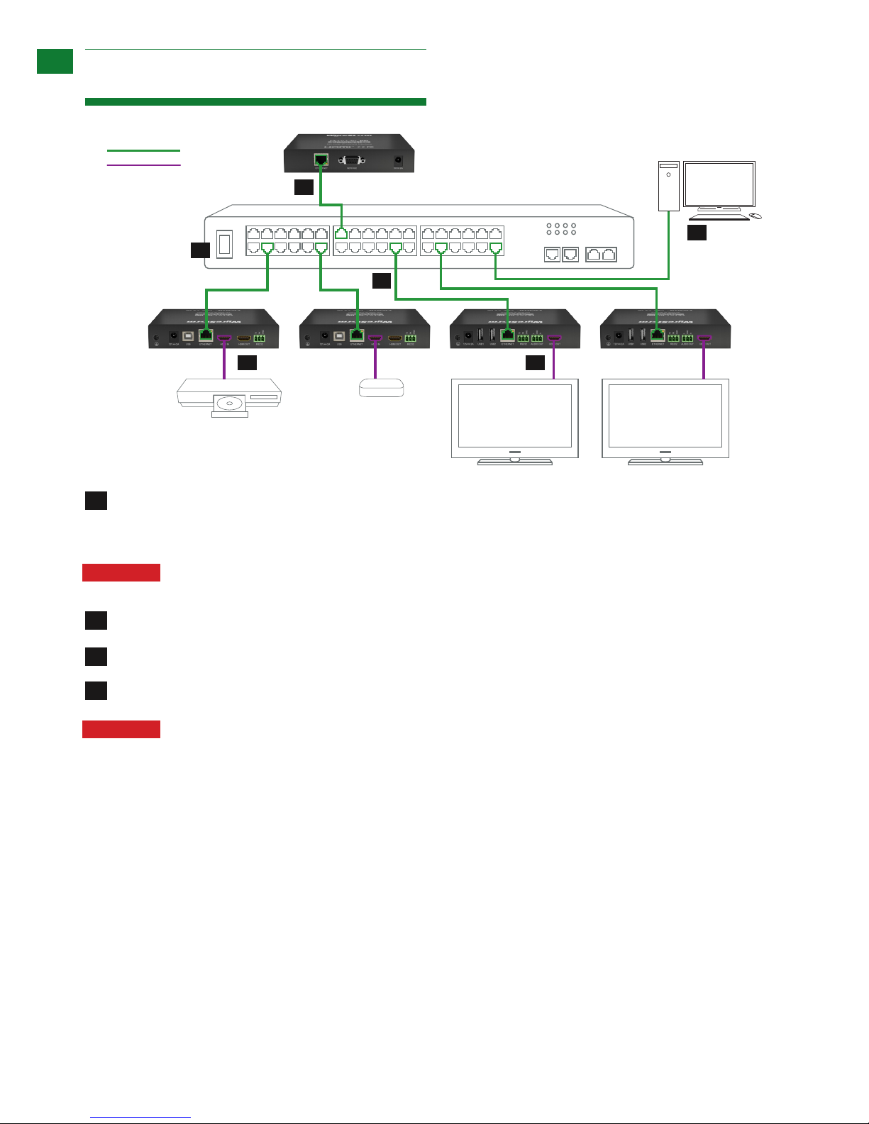
Connection
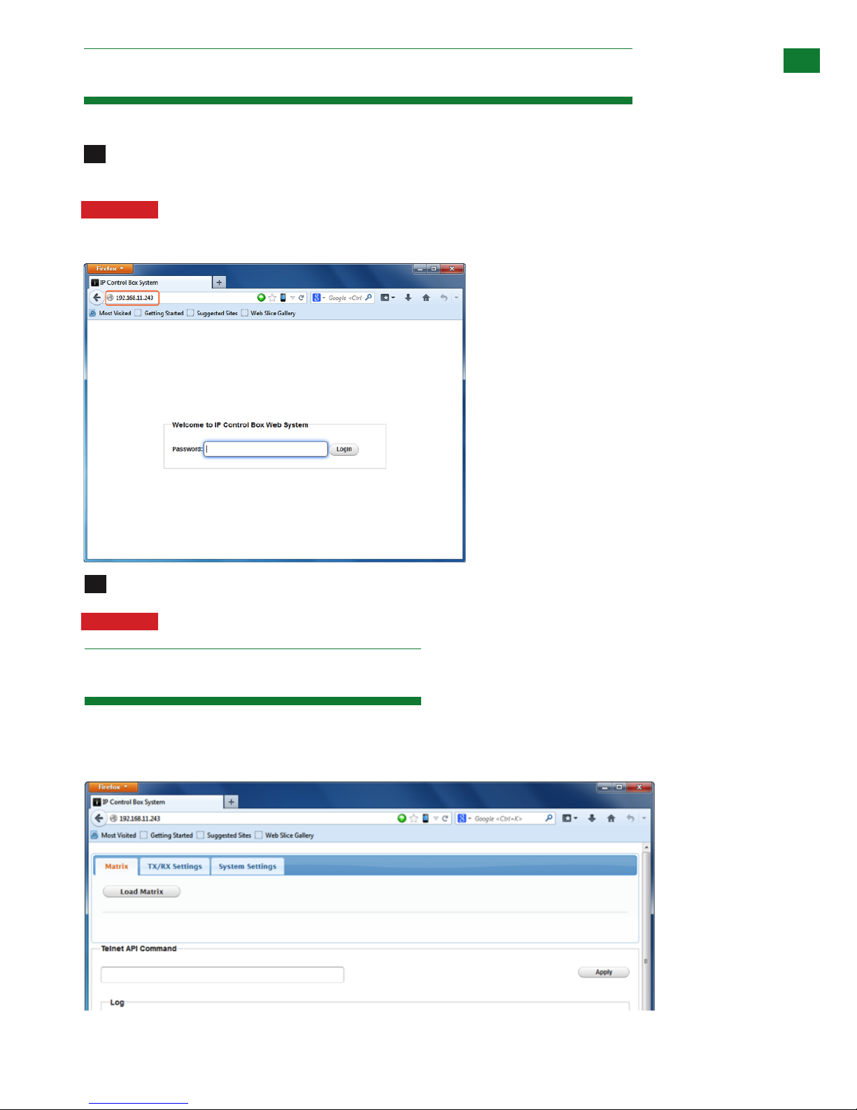
Accessing the NHD-IP-CTL web interface
Basic Operation
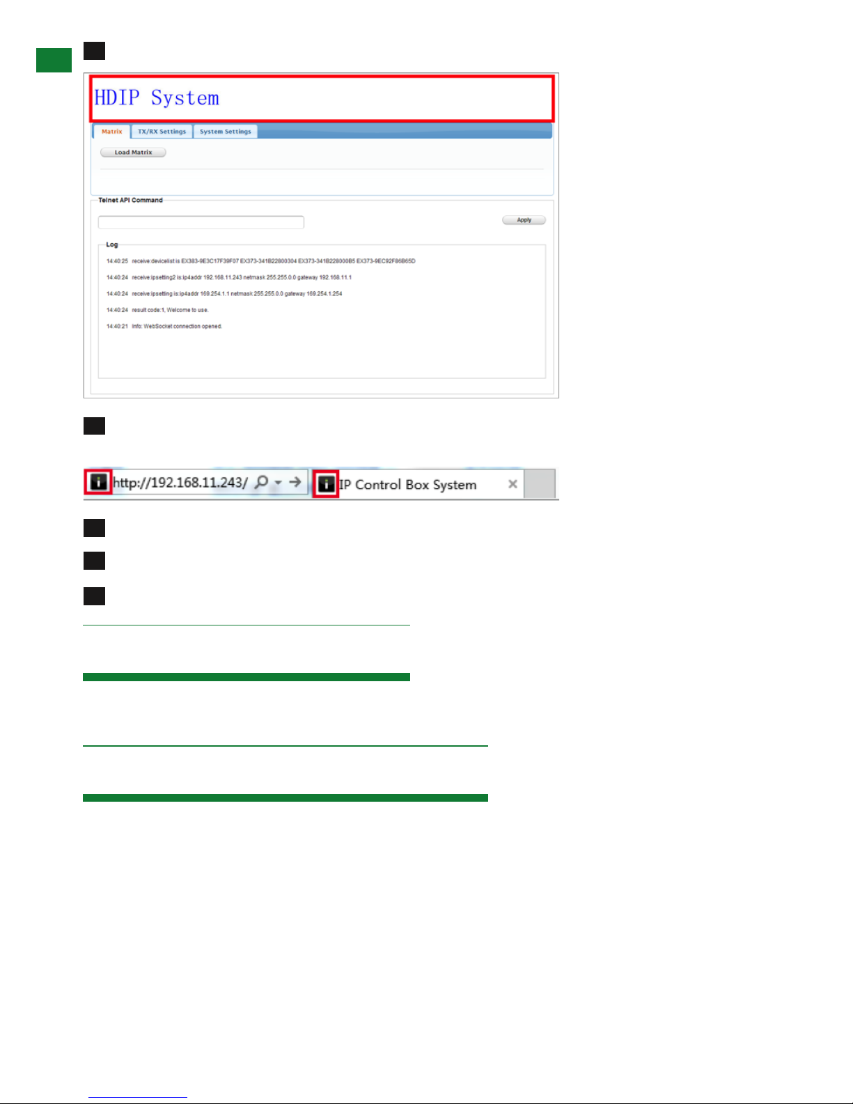
i. Home Screen
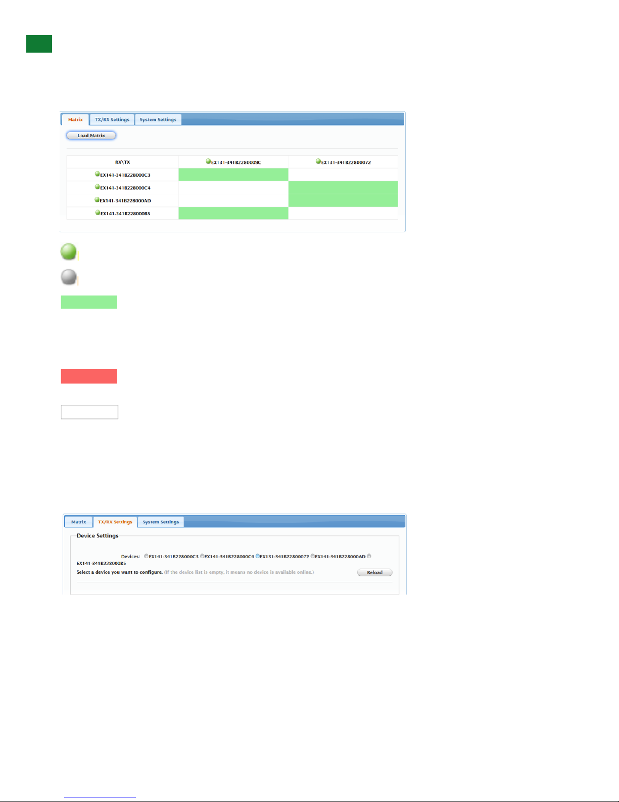
ii. Matrix
iii. RX / TX
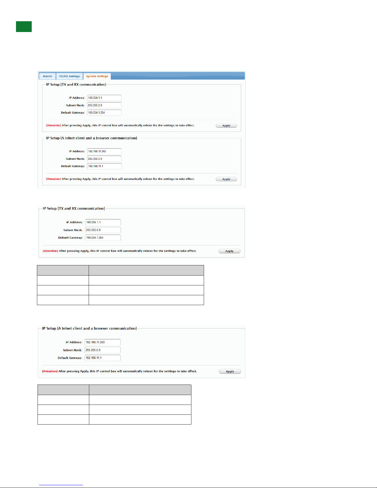
iv. IP Setup
v. Alias (Renaming)
vi. Commands
vii. System Settings
viii. IP Setup (TX and RX communication)
ix. IP Setup (telnet/browser communication)
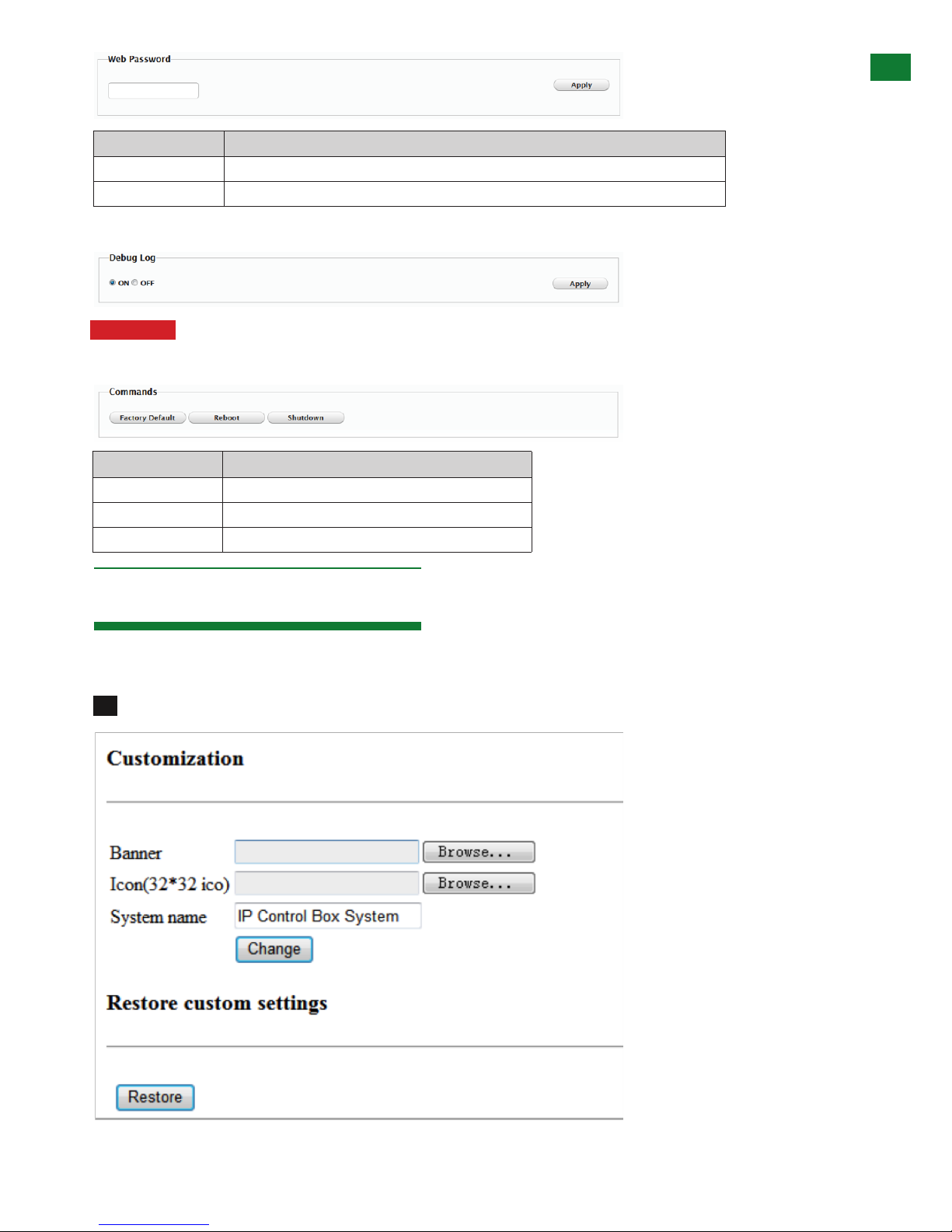
x. Web Password
xi. Debug Log
xii. Commands
Customising the UI
Additional Information
Specications
1
2
3
4
5
6
7
8
9
10
11
13
14
15
19
16
17
18
12
Troubleshooting
FAQ
Maintenance
Provided Service
NetworkHD Telnet Control Protocol
Mail In Service
Installation Reference Logs
i. Warranty
ii. Warranty Limits and Exclusions
3. Safety Precautions
WARNING
To reduce the risk of re, electric shock
or product damage:
4
FEATURES AND SAFETY PRECAUTIONS
MX0404-QI
• Quick and easy installation – set up in seconds straight out of
the box.
• Simplied ports - Input: HDMI – Output: integrated RJ45
connectors for a single Cat5e/6/7 UTP cable to each display
point for ease of installation.
• Conforms to IEEE-568B standards
• Each HDMI port also supports DVI signals.
• Each Output port can be fed to multiple displays (cascaded).
• Enables up to 4 HDMI video/audio devices to be independently
switched through up to 4 HDMI displays or projectors for
uncompressed digital distribution.
• Each output able to show any connected source simultaneously
regardless of whether the input carries HDCP encryption.
• Rened for Custom Install and Home Theatre Installations.
• Reads and copies EDID from connected devices with additional
EDID configuration through customisable DIP switch settings if
necessary.
• 2k resolution supported.
• Fully 3D compatible – Frame sequential 3D (Blu-ray) and
interlaced stereoscopic 3D (satellite broadcasts etc.)
• Supports all high denition resolutions up to and including
1080p and standard video formats.
• RS232 port.
• Choose from 6 switching modes – infrared remote control, front
panel buttons, local IR, IR call-back, LAN and RS232.
• Simple switching remote control included, which can also be
learned into a universal remote handset to allow the control of
multiple devices from one handset.
• Fully compatible for integration with market leading control systems.
• 4 x IR 3.5mm mini-jack ports for each output to link IR from
control system to control display
• Additional infrared extension port for longer IR connections
• HDMI v.1.3
• Supports 24Bit Colour depth
• Signalling rate of 6.75 Gbps
• Pack comes complete with 1 x 4x4 Matrix with 19” rack
brackets, 4 x 40m IR receivers with mounting brackets, IR
receivers, emitters and a Matrix remote control handset.
Additional features included on the RX-1UTP-IR-40
• Transmits one-way signal together with the HDMI signal over a
single Cat5e/6/7 cable.
• Receivers capable of 1080p transmissions up to 40m (131ft)
under ideal conditions*
• For even greater control and ne tuning, each receiver features
a fully adjustable EQ distance range for optimising the
transmission signal.
2. Features
3. Safety Precautions
1. Do not expose this apparatus to rain, moisture, sprays,
drips or splashes and ensure that no objects containing
liquids are placed on the apparatus, including cups,
glasses and vases.
2. Do not place this unit in a confined space such as
enclosed shelving, cabinets or bookshelves. Ensure the
unit is adequately ventilated.
3. To prevent the risk of electric shock or fire hazard due to
overheating, do not cover the unit or obstruct ventilation
openings with material, newspaper, cardboard or
anything that may restrict airflow into the unit.
4. Do not install near external heat sources such as
radiators, heat registers, boilers or any device that
produces heat such as amplifiers or computers and do
not place near sources of naked flame.
5. Unplug apparatus from power supply during lightening
storms or when unused for long periods of time.
6. Protect the power cable from being walked on, pinched
or restricted in any way, especially at plug connections.
7. Only use attachments/accessories specified by the
manufacturer.
8. Units contain non-servicable parts - Refer all servicing to
qualified service personnel.
WARNING
To reduce the risk of fire, electric shock
or product damage:
• Protection against ESD (electrostatic discharge) included within
the unit to further stabilise transmission.
• LED indications for clear power and video signal selection.
• 5v mains supply included but receivers may be powered through the
USB port of the display using Wyrestorm USB to 5v power adaptor)
• Fully cascadable to further lengthen transmission.
*NOTE: ideal conditions denote cable run is within
specified distance range of product, no electrical
interference, the use of straight cable runs with no bends
or kinks and no patch panels or wall outlets used. Please
be advised that the presence of any of these factors in
your installation may compromise bandwidth and signal
strength. For longer transmission distances, RS232 control
and Ethernet pass-through, please see our full HDBaseT
or HDBT Lite range of matrices, transmitters, receivers and
extender sets.
USB to 5V Cable
Part Number CAB-USB-5V