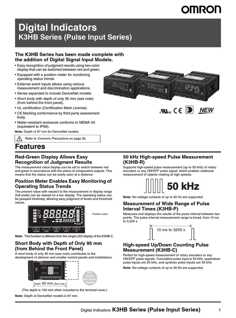
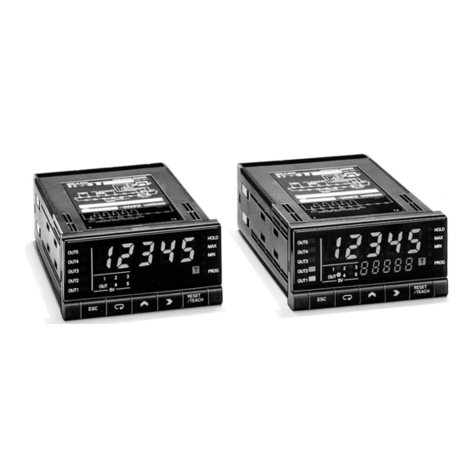
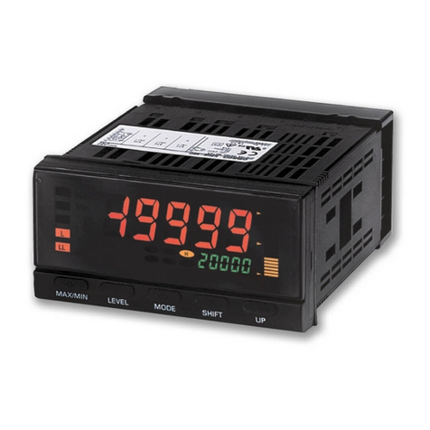
Omron AX-OP05-E User manual

Cat. No. Ixxx-Ex-xx-X
DRAFT V0.90
LCD 5 LINE
DIGITAL OPERATOR
USER’S MANUAL

LCD Digital Operator
LCD Digital Operator User's Manual v0_90 110218.doc 2 Issue 0.90 Draft
Table of Contents
1. Introduction........................................................................................................................................ 4
1.1 Main Features ............................................................................................................................... 4
1.2 Unpacking and Inspection............................................................................................................. 4
2. Name of parts and contents............................................................................................................. 5
2.1 Operation Key ............................................................................................................................... 6
2.2 LCD display................................................................................................................................... 7
2.3 Connection, wiring, and attaching................................................................................................. 8
3. Operation............................................................................................................................................ 9
3.1 Changing Display Modes.............................................................................................................. 9
3.2 Option Mode................................................................................................................................ 10
3.3 Details of Option mode................................................................................................................ 11
3.4 Monitor-A Display Mode.............................................................................................................. 12
3.5 Monitor–B Display Mode............................................................................................................. 13
3.6 Function Mode ............................................................................................................................ 14
3.7 Trip Mode.................................................................................................................................... 15
4. Read/Write function and operation................................................................................................ 16
4.1 R/W Storage Mode - Single READ function................................................................................ 16
4.2 R/W Storage Mode - Single WRITE function.............................................................................. 17
4.3 R/W Storage Mode - Quad READ Function................................................................................ 18
4.4 R/W Storage Mode - Quad VERIFY Function............................................................................. 20
4.5 R/W Storage Mode - Quad WRITE function............................................................................... 21
4.6 Operation condition of Read and Write function......................................................................... 23
5. Inverter setting concerning LCD Operator ................................................................................... 24
6. Error Message.................................................................................................................................. 25
7. Trouble shooting ............................................................................................................................. 26
8. Specification .................................................................................................................................... 27
9. Battery exchange............................................................................................................................. 28

LCD Digital Operator
LCD Digital Operator User's Manual v0_90 110218.doc 3 Issue 0.90 Draft
Thank you for purchasing LCD digital operator. This instruction manual is written about how to use
LCD digital operator.
You could use this manual for inspection, maintenance, setting and use it with the main body of
inverter. After reading this manual, keep it handy for future reference.
SAFETY
To get best performance with LCD digital operator, read this manual and all of the warning sign
attached to the inverter carefully before installation and operation, and follow the instruction exactly.
A safety instruction (message) is given with a hazard alert symbol and a signal word; WARNING or
CAUTION. Each signal word has the following meaning throughout this manual.
This symbol means hazardous high voltage. It used to call your attention to items
or operations that could be dangerous to you and/or other persons operating this
equipment. Read these messages and follow these instructions carefully.
This is the “Safety Alert Symbol”. This symbol is used to call your attention to
items or operations that could be dangerous to you and/or other persons
operating this equipment.
Read the messages and follow these instructions carefully.
WARNING
Indicates a potentially hazardous situation which, if not avoided, can result in
serious injury or death.
CAUTION
Indicates a potentially hazardous situation which, if not avoided, can result in
minor to moderate injury, or serious damage of product.
The matters described under may, if not avoided, lead to serious
results depending on the situation. Important matters are described in CAUTION
(as well as WARNING), so be sure to observe them.
NOTE
NOTE
It indicates an area or subject of special merit, emphasizing either the product’s
capabilities or common errors in operation or maintenance.
HAZARDOUS HIGH VOLTAGE
Motor control equipment and electronic controllers are connected to hazardous line voltages. When
servicing drives and electronic controllers, there might be exposed components with cases or
protrusions at or above line potential. Extreme care should be taken to product against shock.
Stand on an insulating pad and make it a habit to use only one hand when checking components.
Always work with another person in case an emergency occurs. Disconnect power before checking
controllers or performing maintenance. Be sure equipment is properly grounded. Wear safety glasses
whenever working on electronic controllers or rotating electrical equipment.
LCD Digital Operator
LCD Digital Operator User's Manual v0_90 110218.doc 4 Issue 0.90 Draft
1. Introduction
1.1 Main Features
LCD digital operator features state-of-the-art components and functions to provide user-friendly
interface. LCD digital operator can connect to MX2, RX and LX inverters and has 5-line display that
shows parameters by function code and by name. This allows you to operate the inverter remotely, via
a cable.
It has the additional capability of reading up to 5 Parameter Sets or a Parameter Set + Drive
Programming application from the inverter and store into the LCD digital operator memory. It is
possible after to copy them to another inverter.
1.2 Unpacking and Inspection
Please take a few moments to unpack your new LCD digital operator and perform these steps:
(1) Look for any damage that may have happened during shipping.
(2) Verify the contents of the box including LCD digital operator (with built-in battery)
(3) Inspect the name plate and make sure it matches the product part number you ordered.

LCD Digital Operator
LCD Digital Operator User's Manual v0_90 110218.doc 5 Issue 0.90 Draft
2. Name of parts and contents
NO.
Name of parts Color Contents
1 Power Led Green
Light on when power is supplied to the LCD digital operator.
2 Run Led Green
Light on when the Inverter is running.
3 Warning Led Red Light on when set value is incorrect.
4 Alarm Led Red Light on when the inverter trips.
5 Remote Led Green
Light on when the REMOTE key makes the compulsion
operation function effective. It doesn’t light when the
compulsion operation function is effective by input terminal
OPE. (Press the key more than 2 seconds)
6 Key Enabled Led Green
Light on only when operation command is set in LCD digital
operator.
7 LCD Display Please refer to point 2.2 for details.
8 Operation Key Please refer to point 3 for details.
9 Connector It can be connected to the main body of the inverter via a cable
(optional)
10 Hole for installation It is the hole for installation on the control panel. Please fix from the
backside with the M3 screw.
11 Case fixation screw Please unscrew these four screws and detach the case when
exchanging the battery for clock IC.
1. POWER LED
2. RUN LED 3. WARNING LED
4. ALARM LED
7. LCD display
5. REMOTE LED
6. KEY
ENABLED LED
8. OPERATION
KEY

LCD Digital Operator
LCD Digital Operator User's Manual v0_90 110218.doc 6 Issue 0.90 Draft
2.1. Operation Key
NO.
Key image Key Name Function
1 REMOTE
It changes from Local to Remote mode. Press the key
during 2 seconds to change from Local to Remote or
Remote to Local. When it is in Local the OPE led will be
ON. Use Local to control the motor with LCD digital
operator keys (Run Fwd, Run Rev and Stop/Reset).
2 READ It transfers inverter parameters to the LCD digital operator’s
memory. (Refer to chapter 4 for more details.)
3 WRITE It copies one Parameter Set or a Parameter Set + EzSQ
(Drive Programming) saved in LCD digital operator to the
inverter. (Refer to chapter 4 for more details.)
4 ESC It returns to the above layer.
5 SET It jumps to the below layer or stores the change introduced
on the edit layer (after that it jumps to the above layer).
6 UP It is used to move up the cursor, it increases a function code
in 1 or increases a parameter value.
7 DOWN It is used to move down the cursor, it decreases a function
code in 1 or it decreases a value.
8 LEFT CURSOR It is used to move the cursor to the left or it moves to
previous mode when the display is at navigation level.
9 RIGHT CURSOR It is used to move the cursor to the right, or it moves to the
next mode when the display is at navigation level.
10 FWD RUN It is used to run forward the motor only when the operation
command (A002) is set in Digital operator.
(Check KEY ENABLED LED)
11 REV RUN It is used to run reverse the motor only when the operation
command (A002) is set in Digital operator
(Check KEY ENABLED LED)
12 STOP/RESET
It is used to stop the motor or reset an alarm. It is also
possible to invalidate the STOP key by B087 parameter.
Besides it does not response when LCD digital operator is
reading or writing the parameters from/to the inverter.

LCD Digital Operator
LCD Digital Operator User's Manual v0_90 110218.doc 7 Issue 0.90 Draft
2.2. LCD Display
Backlight
There are two backlight colors in the LCD display, white and orange.
They reflect the state of the inverter as follows:
Backlight Color
Contents
White Normal (It is not related to inverter driving/stop)
Orange Warning (Parameter mismatch)
White ↔Orange
(Alternate blinking for one second) Trip (The same as ALARM LED)
Details of LCD Display
The first line of LCD monitor always displays the Display Mode, the Motor Selected, the Inverter RUN
Status and the Display Selection.
Item Content of Display Content
MONITOR-A Monitor-A mode
MONITOR-B Monitor-B mode
FUNCTION Function mode
TRIP Trip (error) mode
WARNING Warning mode (Alarm)
Display Mode
OPTION LCD Configuration Mode
M1 Motor 1 (SET multifunction = OFF)
Motor selected M2 Motor 2 (SET multifunction = ON)
STOP Stopped
FWD Forward running
Inverter RUN Status REV Reverse running
ALL Display all
UTL Function individual display
USR User setting display
CMP Data compare display
Display Selection (b037)
BAS Basic display

LCD Digital Operator
LCD Digital Operator User's Manual v0_90 110218.doc 8 Issue 0.90 Draft
2.3 Connection, wiring, and attaching
Please process the control panel as shown, and fix from the other side with M3 screw (5mm) when
you install the operator on the control panel. Recommended torque is [0.9, 1.0] Nm.
80
18
4026.5
2-M3x5 (Backside)
2-Φ4
Recommended cable
Model Content
ICS-1 1m cable
ICS-3 3m cable
ICS-5 5m cable
Make sure to use a straight cable within 5m in length and 10BASE-T category 5 (CAT5) of UTP or
STP when the cable is prepared by the customer.
NOTE: UTP (Unshielded twist pair cable), STP (Shielded twist pair cable)

LCD Digital Operator
LCD Digital Operator User's Manual v0_90 110218.doc 9 Issue 0.90 Draft
3. Operation
3.1 Changing Display Modes
LCD digital operator has four display modes which can be changed from one to another by
pressing the
or key at Navigation level. Moreover, there are 3 other modes called Read
mode, Write mode and Option mode. In any display mode, it moves to Read mode or Write mode via
key or key, and moves to Option mode after pressing , and at the same
time. It returns to display modes via key.
Each mode has its own layers, where contents and parameter settings cannot be changed at
Navigation level.
When pressing key at Navigation level, a cursor will appear on below layer.
· LCD Navigation levels
To move among the different Navigation levels press keys
or
The outline of each mode is shown as below.
Monitor Mode A
The “d” group inverter parameters and “F~U” group inverter
parameter are displayed on the same screen in this mode. The
content of “d” group parameter is displayed with big font characters.
The function code such as “F001” and contents of “F~U”
parameters are displayed, without the function name.
Monitor Mode B (Monitor x 4)
In this mode, four “d” group inverter parameters can be displayed at
the same screen. The function codes of these parameters are not
displayed.
Function Mode (setting)
In this mode, “F~U” group parameters can be displayed and set.
Function code, function name, parameter content and parameter
range are shown.
NOTE: “d” group inverter parameter cannot be set and displayed in
this mode.
Trip Mode
Trip information and warning information are displayed in this
mode. With inverter trip or a warning happens, the trip screen will be
displayed from any display modes.
In Option Mode, Read Mode and Write Mode, the LED or
WARNING LED will light up.

LCD Digital Operator
LCD Digital Operator User's Manual v0_90 110218.doc 10 Issue 0.90 Draft
3.2 Option Mode
1- Please press and and key at the same time to
enter into the OPTION MODE. The cursor will appear in the first row
of
the Option Mode menu. Use or key to move between the
option Mode menu. To return to the navigation layer, press the
key.
2- Select the Language option and press the key. The cursor will
appear in the Language option value. Use the or key to
select the value to set. Press the key to store the new value
Press the key to cancel the new value.
And then
3- The cursor will appear in the second row (2. Date and Time).
4- Pressing the key, it enters to the Date and Time layer. Use
the or key for moving between the Day, Month, Year,
Hour, etc… data. When the cursor is over the selected data, pressing
or key to change the value.
The change will be stored after
pressing the key.
The settings available in this mode are:
1. Language
2. Date and Time
3. Read Lock
4. INV Type Select
5. R/W Storage Mode
6. Backlight Auto-off
7. Backlight Flicker
8. Operator Reset
9. Check Mode
Use or for moving between the Option Mode Menu.

LCD Digital Operator
LCD Digital Operator User's Manual v0_90 110218.doc 11 Issue 0.90 Draft
3.3 Details of Option mode
Item Content Setting range Default
Language Setting language
01: English
02: Deutsch
03: Français
04: Español
05: Italiano
06: Português
07: 日本語 (Japanese)
08: 中文 (Chinese)
09: Türkçe
10: PycckИЙ
01
Date and Time Setting Date and Time for the LCD
digital operator
Date: 2000/1/1~2099/12/31
Time: 00:00~23:59
Format 1~3
2009/01/01
00:00
1
Read Lock
Set “Read lock” enable to disable, in
order to protect the parameter saved in
LCD digital operator from being
overwritten.
01: Enable
02: Disable
02
INV Type
Select
Please select the correct INV type
using LCD digital operator,
otherwise, ”COM ERROR” will be
displayed automatically.
01: Type 1 (MX2, LX)
02: Type 2 (RX)
01
R/W Storage
Mode
Sets the number of parameter sets for
READ/WRITE mode.
(Refer to chapter 4 for more details.)
01: Single
02: Quad
02
Backlight
Auto-Off
When LCD digital operator remains
without key operations for 1 minute,
LCD backlight will be turned off. When
a key is pressed it will turned on.
The Backlight Auto-Off function does
not work when trip happened.
01: Off
02: 1 minute
01
Backlight
Flicker The Orange backlight will be enabled
or disabled.. 01: Enable
02: Disable
01
Operator
Reset
Use this function to return to default
settings of LCD digital operator.
The next items will be reset:
1) Language: English
2) Date and time:2009/01/01 THU
00:00
3) Time format: 01:YY/MM/DD
4) Read lock: Disable
5) R/W Storage Mode: Quad
6) Backlight Auto-Off: Off
7) Backlight Flicker: Enable
After this, date and time setting is
required.
01: YES
02: NO
02
Check Mode Check if LED and key etc. are normal
or not.
Key&Led Check, Lcd Check,
EEPROM Check, RTC
Check, Serial Loopback,
Debug Mode, Firmware
Version.
-
NOTE: Please do not execute the EEPROM check. Otherwise, the data (parameters/EzSQ program)
saved in LCD digital operator will be erased.

LCD Digital Operator
LCD Digital Operator User's Manual v0_90 110218.doc 12 Issue 0.90 Draft
3.4 Monitor-A Display Mode
1- Please select monitor mode A by using the or
key at the
navigation layer. The cursor will be displayed in the Monitor-A pressing
the key.
2- After that, use the or key to select the function code to be
displayed into the Monitor-A.
Use or key to move the cursor to the function code (F001
in this case) and use the or key to change the function code,
3- Use the key to access to the function code value. With the
or key the value can be changed. The changes will be
stored after pressing the key or cancelled pressing the
key.

LCD Digital Operator
LCD Digital Operator User's Manual v0_90 110218.doc 13 Issue 0.90 Draft
3.5 Monitor–B Display Mode
1- Please select the Display Mode Monitor-B using the or
key at the navigation layer.
2- After pressing the key the cursor will appear on the first row of
the four “d” group inverter parameters. Use the or key to
move between the four Monitor-B inverter parameters.
3- Pressing the key the cursor will appear on
the function code of
the “d” inverter parameter selected. Use the or key to select
other function code.
·Pressing the key, the function code is selected, and then
displayed on the Monitor-B display Mode.
·Pressing the key, the change will be cancelled..

LCD Digital Operator
LCD Digital Operator User's Manual v0_90 110218.doc 14 Issue 0.90 Draft
3.6 Function Mode
1- Please select Function Mode by using the or key at the
navigation level.
2- Pressing the key the cursor will appear in the function code.
Then use the , , or key to select the function
that will be changed.
3- After that, pressing the key the cursor will appear in the
parameter value. Use the or key to select the value to be
set.
· To store the parameter value, press the key.
·Pressing the key, changes will be cancelled.

LCD Digital Operator
LCD Digital Operator User's Manual v0_90 110218.doc 15 Issue 0.90 Draft
3.7 Trip Mode
1- Select the or key to select trip mode at the navigation
layer.
2- Pressing the key
, the past trip information (6 trip errors) and the
warning information (1 time), that are recorded on the inverter, will be
displayed. Trip information is composed in two pages. For change from
page 1 (P1) to page 2 (P2), press the or key.
Pressing 6 times the key, it will be displayed the Warning Mode.
NOTE: When a trip happens, ALARM LED will be light on. Press the key to reset the inverter.

LCD Digital Operator
LCD Digital Operator User's Manual v0_90 110218.doc 16 Issue 0.90 Draft
4. Read/Write function and operation
LCD digital operator can read and save Inverter parameter settings, and copy them to another inverter.
Specifically LCD digital operator can save four inverters’ parameter sets or one inverter’s
parameter set and its EzSQ (Drive Programming) program. It can be selected via the R/W
Storage Mode in the LCD configuration Option Mode.
Note: If Read operation cannot be executed, please check the Read Lock option in the LCD
configuration Option Mode.
4.1 R/W Storage Mode - Single READ function
When the R/W Storage Mode is selected to “01:Single” (this is done in the LCD configuration :
Option Mode), the function Read or Write is executed immediately after pressing or key.
After pressing the key in any display mode, except Write mode and Option mode, the
inverter’s parameter configuration are read and saved into LCD digital operator EzSQ (Drive
Programming) program will be transferred to the LCD digital operator automatically after parameter
reading is finished. If the inverter supports EzSQ (Drive Programming) function, it returns to the
previous display after read function is completed.
When the inverter does NOT support EzSQ (Drive Programming) function
Parameter reading.
Read “completed” will display
for 2 seconds
When parameter read function is completed, it
will return to previous display automatically
When the inverter supports EzSQ (Drive Programming) function
When read is completed, it will
return to previous display
automatically
Parameter reading.
EzSQ (Drive Programming) reading.
NOTE: All inverter parameters saved in LCD digital operator are overwritten after the key is
pressed.

LCD Digital Operator
LCD Digital Operator User's Manual v0_90 110218.doc 17 Issue 0.90 Draft
4.2 R/W Storage Mode - Single WRITE function
After pressing the key in any display mode except Read mode and Option mode, the parameter
settings stored in LCD digital operator are transferred to the inverter. If the inverter supports EzSQ
(Drive Programming), it will be transferred to the inverter automatically after the parameter copy is
finished. It will return to the previous display after write function is completed.
When the inverter does NOT support EzSQ (Drive Programming) function
Parameter reading.
Read “completed” will display
for 2 seconds
When parameter write function is completed, it
will return to previous display automatically
When the inverter supports EzSQ (Drive Programming) function
When write is completed, it will
return to previous display
automatically
Parameter writing.
EzSQ (Drive Programming) writing.
NOTE: Refer to chapter 4.6 for details.

LCD Digital Operator
LCD Digital Operator User's Manual v0_90 110218.doc 18 Issue 0.90 Draft
4.3 R/W Storage Mode - Quad READ Function
When the R/W storage mode is selected to 02:Quad option, it will be possible to handle four sets of
inverter parameters or read/write an EzSQ (Drive Programming) program independently. In this case,
LCD digital operator can save four sets of inverter parameters, or one set of inverter parameters and one
EzSQ (Drive Programming) program. Please note that one EzSQ (Drive Programming) program takes
up three sets of inverter parameters,which are No.2, No.3 and No.4.
When the inverter does NOT support EzSQ (Drive Programming) function
Pressing [ESC] it will return to previous display
Write “completed” will display
for 2 seconds
Automatically it will
return to previous display

LCD Digital Operator
LCD Digital Operator User's Manual v0_90 110218.doc 19 Issue 0.90 Draft
When the inverter supports EzSQ (Drive Programming) function
·In any display mode except Write Mode and Option Mode, the read screen is
displayed after pressing the Key. If there aren’t parameters stored in LCD
digital operator, it will show “—“.
·Use the or key to move the cursor up and down to select the
memory number where parameter setting will be stored.
·After pressing the key the Select data available are:
01: Read data
02: Read data+EzSQ
03: Verify data
04: Verify EzSQ
05: Cancel
NOTE: only three selection items 01, 03 and 05 are displayed when memory
No.2, No.3 or No.4 is selected.
·An overwritten confirming screen are displayed after the
key is
pressed. To approve, press the key, if not, press the key.
·The Read “Completed” will be displayed for 2 seconds.
·It returns to the Read Mode navigation layer automatically after the read
function is completed. The read operation date and time and inverter type will be
updated on the first line.
·Lines No. 2, No. 3 and No. 4 will display “E” as showed in the right figure.

LCD Digital Operator
LCD Digital Operator User's Manual v0_90 110218.doc 20 Issue 0.90 Draft
4.4 R/W Storage Mode – Quad VERIFY function
With and without EzSQ (Drive Programming) inverter support
The resul
t is shown automatically after the
parameter or EzSQ (Drive Programming)
verification
is completed.
It returns to navigation level of Read mode after the
key is pressed.
Other manuals for AX-OP05-E
1
Table of contents
Other Omron Monitor manuals

Omron
Omron K3NC User manual

Omron
Omron K3HB User manual

Omron
Omron Sysmac NA Series User manual

Omron
Omron K3HB User manual

Omron
Omron ns series User manual

Omron
Omron ZN-CTX21 Series User manual

Omron
Omron K3MA-F - User manual

Omron
Omron SMART ACTIVE PARTS User manual

Omron
Omron F3UV Series User manual

Omron
Omron K3NP - 1998 User manual

Omron
Omron NA5-15 101 Series Instructions for use

Omron
Omron ZG2 Series User manual

Omron
Omron K3MA-L User manual

Omron
Omron EQUO Series User guide

Omron
Omron FZ5-110 User manual

Omron
Omron K3HB-H User manual

Omron
Omron NS - User manual

Omron
Omron fz5-l35 series User manual

Omron
Omron F250-UME Quick start guide

Omron
Omron NYM15W-C100 User manual