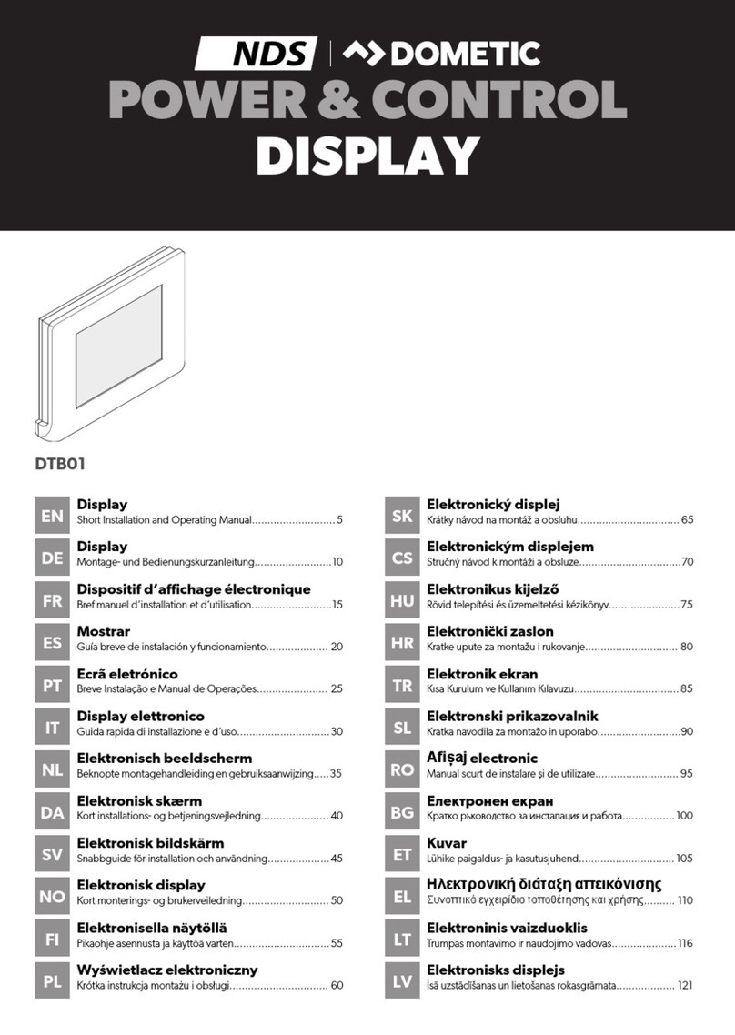
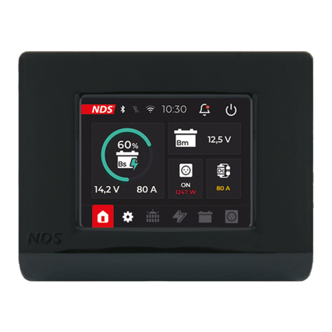
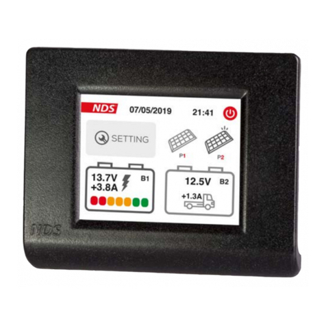
NDS DTB01 User manual

1
DISPLAY BUS
User Manual
ENGLISH
VALID FOR THE MODEL
DTB01

2
INSTRUCTIONS FOR THE PROPER DISPOSAL!
This electronic product is subject to the European
Directive 2012/19 / EU. Comply with local waste disposal
regulations, do not dispose of old products with normal
household waste. The proper disposal of products that
can no longer be used prevents potential negative
consequences for the environment and for the
population.

INDEX
1. SAFETY INSTRUCTIONS 2
2. PACKAGE CONTENTS 3
3. DESCRIPTION 3
4. MAIN FEATURES 4
5. DISPLAY STRUCTURE 4
6. INSTALLAZIONE 5
7. SETUP INIZIALE 6
8. SCREEN STRUCTURE 11
9. CUSTOM CHARGING CURVE 13
10. OTHER SETTINGS 15
11. BATTERIES 17
12. BATTERY CHARGERS DC-DC 18
13. SOLAR REGULATORS AND SOLAR
PANELS 19
12. TECHNICAL FEATURES 20
12. WARRANTY 22

1. SAFETY INSTRUCTIONS
• Child Safety: Keep the device Out of Reach.
• Carefully check the integrity of the device and
connectors.
• To avoid overheating and possible fires do not install
the device in a sealed environment, Always choose a
well ventilated area.
• Do not place the device on highly flammable
surfaces or environments (eg: paper, cloth, etc.).
• Do not cover the cooling slits on the side and the fan
on the top.
• Do not install the device near flooded batteries: they
produce flammable, corrosive and explosive gas
while working, and it can damage the product.
• Protect the device from sunlight or direct sources of
heat.
• To avoid malfunctions, DO NOT install and use the
device in very humid environments, in contact with
water splashes, various liquids, or exposed to rain.
• To avoid risk of electric shock and/or fire, the
vehicle's fuel system must be in good condition.
• In case of damaged connecting cables or
inadequate section, immediately replace them with
suitable cables as specified by this manual or by a
qualified electrician.
• In case of anomalies in the conformity of the
product do not use it! it is strictly forbidden to open
the device. Repairs may only be carried out by
qualified technical personnel using original spare
parts.
• Keep the instruction manual near the device for
easy access to the essential safety, use and
maintenance information.
• The information contained in this manual may be
changed without notice. NDS Energy s.r.l. reserves
the right to make changes and improvements to the
product at any time without notice and without
obligation to apply these changes to the devices
previously distributed.
2

• The images of the products are purely indicative and
may therefore not be fully representative of the
characteristics of the product, differing in color, size
or accessories.
2. PACKAGE CONTENTS
Check the package content:
•1x DTB01 display bus Controller
•1x Connection cable
•1x Frame for wall mounting
•4x Mounting screws
3. DESCRIPTION
DTB01 is the optional controller with new user interface
for NDS devices with N-BUS communication protocol.
Connect N-BUS devices to each other with the data cable,
connect the DTB01 Display Bus to the network, and you
have the full power of the NDS power system at your
fingertips.
With the DTB01 you can control all N-BUS equipped
devices, such as: Tempra Lithium Battery, Power Service
PSB DC-DC, Suncontrol2 SCE.
In addition to the DTB01 display you can also use the App
for iOS and Android smartphones, if there is an NDS
device with Bluetooth in the N-BUS network.
3
NOTE
• NDS devices of the previous generation are not compatible
with DTB01.
• Only NDS devices with N-BUS can be monitored and
controlled by DTB01.

4. MAIN FEATURES
•N-BUS device energy parameter monitoring: State of
Charge (SoC) of Tempra battery, Solar Energy, DC-DC
charge when vehicle is in motion.
•Accurate, real-time consumption monitoring.
•Control of all N-BUS devices to activate or deactivate
a device, choose charge curve, select settings in
general.
•Voltage and ampere charge display Date and time.
5. DISPLAY STRUCTURE
4
N°
FUNCTION
1
Touch screen Display
2
Communication cable hole
3
4 holes for wall fixing
4
Display cover plate to mounting frame fixing holes
DISPLAY
MOUNTING FRAME
1
4
2
3
3
3
4
4
4
3

6. INSTALLAZIONE
1. Remove the DBT01 mounting frame
2. Place the mounting frame on the wall chosen for
installation and take marks for:
• holes for the fixing screws (diameter 3mm);
• hole for the communication cable pass through
(minimum diameter 7.2mm).
3. Drill the holes and screw mounting frame to the
wall, using the screws provided, be sure that they do
not protrude once screwed in.
4. Pass the communication cable (white connector)
through the hole previously made and insert it
gently onto the display board.
5
CAUTION
Do not force the connector into the housing: the right direction is
unique!
a. Slide the display
cover plate
upwards in
relation to the
rear mounting
frame
b. Lift up the lower
part of the display
cover plate
c. Slide the display
cover plate
downwards, in
relation to the
mounting frame,
and release it

5. Fasten the display to the anchor bracket as required.
6. Connect the DTB01 display to an NDS device with N-
BUS.
7. SETUP INIZIALE
The DTB01 Bus Display allows you to set up and control
all networked N-BUS devices. When the display is
started for the first time, it searches for all connected
devices and displays the setup menus of all devices
(e.g. Suncontrol2 SCE, Lithium Battery Tempra) in
succession.
Follow the steps below to best set up your N-BUS
network using the DTB01 Display:
1. Connect the DTB01 display to an N-BUS device.
6
a. Insert the display
cover plate fixing
tabs into the
appropriate
housing of the
mounting frame
b. Lower the bottom
side of the display
cover plate by
making it stick to
the mounting
frame
c. Slide the display
cover plate
downwards in
relation to the
mounting frame

2. Press the button on the side of the display frame.
A short press (1 second) of the side button switches
on the display and all connected N-BUS devices.
A long press (5 seconds) of the side button switches
off the display and all connected N-BUS devices.
3. After the start-up screen, set the required data by
moving through the various screens with the
selection buttons. As shown in the figures below.
Setup can also be completed later.
7
NOTE
When starting the DTB01, only the setting menus for the
connected devices are shown in succession.

8
STEP 1 - POWERING UP
After pressing the power
button, the loading screen is
displayed and the N-BUS
network is initialized.
STEP 2 - LANGUAGE
Set the desired language.
Press the red button at the
bottom right to go to the
next screen.
You can skip this step and
go directly to the home
page by clicking on the
arrow at the bottom left.
STEP 3 - DATE
Set the date by pressing the +
a n d - b u t to n s b e l ow t h e
reference box. When finished,
continue to the next screen by
pressing the red button at the
bottom right. Or go back with
the bottom left button.

9
STEP 4 - TIME
Set the time with the + and -
buttons.
When finished, continue to the
next screen by pressing the red
button at the bottom right. Or
go back with the bottom left
button.
STEP 5 - BATTERY SETTINGS
Set the capacity and technology
of the leisure battery to be used.
When finished, continue to the
next screen by pressing the red
button at the bottom right. Or
go back with the bottom left
button.
STEP 6 - CHARGING CURVE
Set the correct charging curve
in relation to the selection
made in step 5. Click on the
number at the side of the
technology (technologies not
suitable according to step 5 will
not be selectable).
The number will be highlighted
in green.
When finished, continue to the
next screen by pressing the red
button at the bottom right. Or
go back with the bottom left
button.

10
To get more information on the
charge values, click on the arrow for
the desired charge curve, the display
screen for the technical charge data
will open.
NOTE
When the Tempra Battery is connected to the N-BUS network,
the values for technology and Ah will automatically be set and
cannot be changed. The charging curve will automatically be set
to LiFePO4(No. 5).
STEP 7 - SOLAR REGULATOR
Set the power (W) of the
connected solar panels using
the plus and minus buttons on
the side.
When finished, continue to the
next screen by pressing the red
button at the bottom right. Or
go back using the bottom left
button.
HOME SCREEN
After finishing the setting
screens, you arrive at the
Home Screen.

8. SCREEN STRUCTURE
The Home screen consists of an upper status bar
(Status Bar), a central part dedicated to device widgets,
and a lower navigation bar (Tab Bar).
The tab bar shows the icons of the active devices
connected to the N-BUS network, the setting icon
(Settings) and the return button to the Home Screen
are also shown.
11
Status Bar
Tab Bar
Device Widgets
TAB BAR
Solar regulator
Screen
Home
Battery charger
screen
Settings
Screen
Batteries
Inverter
Screen
x2
2

The Status Bar displays icons relating to Bluetooth
connectivity and 220V mains presence.
The time, alarm notifications and the display standby
button are also shown.
The widget section varies in order and form according
to the connected devices.
12
STATUS BAR
Bluetooth
icon
Notifications
icon
Time
Display
backlight off
Main 220V
Presence
DEVICE WIDGET

9. CUSTOM CHARGING CURVE
With the DTB01 you can set a customized charging
curve for your batteries to match the manufacturer's
requirements.
Follow the steps below to change the charging curve.
13
STEP 1
From the home screen, click
on the gear symbol to enter
the settings menu.
STEP 2
Move around the menu with
the arrows at the bottom. Click
on the red button at the
bottom right to reach screen
2/3 and click on Charging
Profile

14
STEP 3
Set the desired values
using the + and - buttons
on the side, then proceed
to the next screen using
the red button at the
bottom right.
T h e s e t t i n g v a l u e s
correspond to the steps
perfor m e d by modern
battery chargers, these
values are usually provided
b y t h e b a t t e r y
manufacturer:
Vabs. = Absorption voltage
(absorption)
Vfloat = Float voltage
(floating)
Vstart = Starting voltage
(starting)
Select the desired options
by marking the box, and
set the required value with
the + and - buttons on the
side, then proceed to the
next screen with the red
button at the bottom right.
Float = Enables the float
function. This function
keeps the batteries always
at the optimum state of
charge.
Recondition = enables the
desulphation function,
ideal for Lead/Acid batteries
(AGM, Gel, Wet)
CAUTION
If you are not sure of the values to be set, return to a standard
configuration.

10.OTHER SETTINGS
15
SETTING SCREEN SELECTION
From the home screen, click on
the gear symbol to enter the
settings menu.
SETTINGS SCREEN 1/3
On page 1/3 of the settings
m e n u y o u c a n s e l e c t
settings by ticking the box,
e.g. for
A c t i v a t e / D e a c t i v a t e
Bluetooth.
Activate/Deactivate Silent
mode: silent mode for Power
S e r v i c e P S B a n d
SunControl2 SCE360.
It is also possible to enter
sub-menus, such as for the
Display.

16
The Display submenu allows
you to:
• Set the backlight activity time
• Set the time before display
standby.
• Activate/d eac tivate audio
feedback when touching the
display.
Act on the + and - selection
buttons, and finally click on the
red button at the bottom right.
SCREEN SETTINGS 2/3
From this screen you can access
sub-menus to set details
concerning leisure battery,
charging curve and solar panel
power.
SCREEN SETTINGS 3/3
From this screen you can access
sub-menus to set details
rega rding date and time,
l a n g u a g e a n d t h e l i s t o f
connected N-BUS devices.

11. BATTERIES
17
The screen shows all N-BUS
devices connected in the
same network.
The device highlighted in
blue is the Master, i.e. the
Master is the device that
manages all others.
BATTERY SCREEN
Clicking on the battery icon on
the Tab Bar displays all data of
t h e T E M P R A b a t t e r i e s
connected with the N-BUS.
I f t w o o r m o r e T E M P R A
batteries are connected, this
screen will be displayed.

12.BATTERY CHARGERS DC-DC
18
DC-DC SCREEN
If a battery charger or DC-DC
with N-BUS is present in the
N-BUS network, it will be
possible to display the
charging data of the leisure
battery (voltage and current)
and the voltage of the starter
battery. The charging stage
the charger is in is also shown.
Other manuals for DTB01
2
Table of contents
Other NDS Monitor manuals

NDS
NDS DOMETIC SL12-100 User manual

NDS
NDS Radiance Ultra 4K User manual

NDS
NDS DOMETIC SS12-100 User manual

NDS
NDS EndoVue Plus 24 User manual

NDS
NDS DOMETIC BS12-100 User manual

NDS
NDS DT002 User manual

NDS
NDS RADIANCE ULTRA 32 4K ZEROWIRE DUO User manual

NDS
NDS Radiance 32 User manual

NDS
NDS Dometic IM12-150 Owner's manual

NDS
NDS GX2MP User manual