a
A
b
B
c
C
d
D
e
E
f
F
g
G
h
H
i
I
G
J
H
K
l
L
I
M
N
N
o
O
p
P
J
Q
K
R
7SEG
11SEG
7SEG
11SEG
s
S
s
t
T
t
u
U
u
W
V
v
X
W
w
Y
X
x
y
Y
y
Z
Z
z
Y
0
0
1
1
1
2
2
2
3
3
3
4
4
4
5
5
5
6
6
6
7
7
7
8
8
8
9
9
9
■Nomenclature
2) Key operation
Monitoring state is a state in which setting value is displayed in protect setting
mode and setting mode.
Setting state is a state in which setting can be changed.
Symbol
Basic Meaning
Mode State
Description
SHIFT key Measurement mode
Protect setting mode,
Setting mode
・Mode switching
・Determination
・Mode switching
・Cancel
・Transition
Present measurement value
Operation
click
click
click
click
press for more
than 3 sec
press for more
than 3 sec
press for more than 3 sec
click
Change parameters.
ENTER key
Monitoring state Change parameters.
MODE key
UP key
Setting state Change digits.
・Shift to
setting state
・Change the
setting value
S
O
M
U
Setting state Determine the setting value.
click
Monitoring state
Move to communication setting mode.
Setting mode
Measurement mode
Measurement history
Switch measurement history display.
Operation setting mode click
Monitoring state Move to operation setting mode.
Communication setting mode
Measurement history
(current day)
Clear the currently displayed MAX
and MIN value of the present day.
Measurement mode
Present measurement value,
measurement history Move to operation setting mode.
click
Measurement mode
Present measurement value
Move to measurement history.
・Reverse
transition
M+S
(Press the S
key while holding
the Mkey)
click
Measurement mode
Present measurement value
Change parameters in reverse.
click
Setting mode Monitoring state Change parameters in reverse.
Setting mode Monitoring state Move to measurement mode.
click
Setting mode Monitoring state Shift to setting state.
click
Measurement mode,
Setting mode
Pro level Move to “PROLV” of the basic level.
click
Measurement mode,
Setting mode Basic level (“PROLV”
remains displayed) Move to Pro level.
click
Measurement history
Move to present measurement value.
click
Setting state Cancel setting state.
click
Measurement history
Move from measurement history.
click
Setting state Change the setting value.
click
Measurement history
Switch the measurement history display.
click
Setting state Change digits in reverse.
・Change the
setting value
in reverse
・Mode switching
M+U
(Press the Ukey while
holding the Mkey)
M+O
click
Measurement mode
Measurement history
Transit measurement history in reverse.
press for more
than 3 sec
Measurement mode
Protect setting mode
Setting mode
Present measurement value,
measurement history Move to protect setting mode.
click
Setting state
Change the setting value in reverse.
press for more than 3 sec
Monitoring state Move to measurement mode.
■Basic usage
■Segment display
Setting Examples
Applicable circuit type: 1-phase 3-wire
Dedicated CT type: 5ACT
Time: March 5, 2010, 17:15
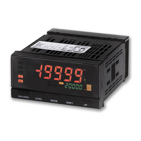
■Display Screen
1) 1st display
Displays the measurement value or type of setting data.
2) 2nd display
Displays the unit or the parameter name of the measurement data or setting data.
3) Operation display
・OUT1:
The light turns ON in conjunction with the output set to the OUT1 terminal.
・STOP:
Lights ON when power is supplied after the time measurement function stops
following back-up power failure during power OFF. Lights OFF by setting time data.
When using the product with lights ON, measurement data log cannot be recorded.
・(Key): Lights ON at protect setting.
4) Temperature unit
When selecting Celsius in the temperature unit setting,
°C
is shown.
When choosing Fahrenheit,
°F
is shown.
abcdefghijk lmnop qr
Item Setting range (1st display)
2nd display Initial value
Remarks
Applicable circuit type 1p2w: 1-phase 2-wire, 1p3w: 1-phase 3-wire,
3p3w: 3-phase 3-wire
Dedicated CT type
Rated primary side current value
Effective only when the dedicated CT type is 5A.
When the simple measurement is ON, sequentially
measure the reactive voltage, VT primary voltage,
and VT secondary voltage.
Unit: V
VT
setting VT primary side
voltage value
VT secondary side
voltage value
Current low-cut value Unit
:
%
Pulse output unitUnit
:
Wh
Display refresh periodoff is instantly updated.Unit
:
Sec
Averaging times.
CO2conversion factor Unit
:
kg-CO2/kWh
Time setting
(Year, month/day,
hour/minute)
Year, month/day, and hour/minute should be set
continuously. If it was canceled in process, all
values will return to previous values. As soon as
setting hour and minute, the settings are reflected.
Set the moving average time of the Moving
average Current.
Cancel it during the input or set a value out of the
range, come back before a change.
Initialization
Moving average time
Setting
set
:
Initialize all setting values except time setting.
max
:
Initialize all the max value of parameters of
the present day.
min
:
Initialize all the min value of parameters of
the present day.
integ
:
Initialize the total integral power consumption.
m.pro
:
Initialize the measurement values in the Pro
level in measurement mode of the present day.
log
:
Initialize all the measurement histories.
all
:
Initialize set values other than clock time
and all measurement histories.
Simple
measurement
setting
Simple
measurementAt ON, set voltage and power factor,
Frequency is 50 Hz fixed.
Fixed voltage value.
Can be set only at simple measurement ON.
Fixed power factor value.
Can be set only at simple measurement ON.
■Setting mode
Operation setting modeBasic level
1p2w, 1p3w, 3p3w 00.typ 3p3w
5a, 50a, 100a, 200a, 400a, 600a 01.c.rg 100a
5
to
9999 02.sct 5
none, 220, 440, 3300, 6600, 11000,
22000, 33000
03.v.rg none
0.1
to
19.9 04.cut 0.6
1, 10, 100, 1k, 2k, 5k, 10k, 20k, 50k, 100k
05.pl5 100
off, 0.5, 1.0, 2.0, 4.0 06.ref 1.0
off, 2, 4, 8, 16, 32, 64, 128, 256, 512, 1024
07.avg 8
0.000
to
99.999 10.co2 0.387
Charge conversion setting
(Rate setting and price
unit setting)
Sequentially set the rate and price unit display.
4-digit price unit can be set.
11.chg 10.000
jpy
2010
to
2099
01 01
to
12 31
00-00
to
23-59
14.tim 2010
01 01
00-00
set, max, min, integ, m.pro, log, all 15.ini set
off, on 08.smp off
0.0
to
9999.9 vlt 110.0
0.00
to
1.00 pf 1.00
110, 220 110
v.rg2
Pulse conversion 1 setting
(Pulse conversion target,
factor, decimal point
position and display unit)
Sequentially set the pulse conversion target, conver-
sion factor, display unit. 4-digit display unit can be set.
c-t.d
:
Sum of pulse input counts
c-1.d
:
Pulse input count 1
c-2.d
:
Pulse input count 2
c-t.a
:
Sum of total pulse input counts
c-1.a
:
Total pulse input count 1
c-2.a
:
Total pulse input count 2
12.cv1 c-1.d
0001
0000
m3-1
Pulse conversion 2 setting
(Pulse conversion target,
factor, decimal point
position and display unit)
13.cv2 c-2.d
0001
0000
m3-2 Protocol select compf: CompoWay/F,modb: Modbus
Unit: bps
Unit: ms
Unit No.
Baud rate
Data bit length (*1) Unit: bit
Stop bit length (*2) Unit: bit
Vertical parity
Time to wait for sending
*1 When protocol is Modbus, data bit length is 8-bit fixed.
*2 When protocol is Modbus, stop bit length cannot be set due to automatic setting.
When vertical parity is NONE, the length is 2, when vertical parity is ODD or EVEN, the length is 1.
*1 It applies to the pulse input count, power consumption rate, pulse input ON time.
*2 When thresholds or hysteresis is set, the operating value which is converted from the setting value (%) is displayed.
Time setting later than the measurement end time cannot
be made.
Time setting earlier than the measurement start time cannot
be made.
Measurement start time (*1)
Measurement end time (*1)
■Protectedmode
Setting
content Limit content
Displayed value transition
Move to setting mode Move to pro level
Clear measurement history
Yes: Permission / No: Prohibited
Change setting content
0Yes
1Yes
2Yes
Yes
Yes
Yes
Yes
No
No
Yes
No
No
Yes
Yes
No
compf, modb 80.psl compf
CompoWay/F: 0
to
99, Modbus: 1
to
9981.u.no
1
1.2k, 2.4k, 4.8k, 9.6k, 19.2k, 38.4k 82.bps 9.6k
7, 8 83.len 7
1, 2 84.sbt 2
none, odd, even 85.prt even
0
to
99 86.sdw 20
00-00 to 23-59
35.5tc 00-00
00-01 to 24-00
36.etc 24-00
Event input 1 N-O/N-C
input mode setting n-o
:
Normally open
n-c
:
Normally close
Event input 2 N-O/N-C
input mode setting n-o
:
Normally open
n-c
:
Normally close
Operation setting modePro level
n-o, n-c 33.in1 n-o
Event input setting p.csp
:
Electric power consumption rate,
h-on
:
Pulse input ON time
,3-st
:
3-STATE
p.csp, h-on,
3-st
30.ei5 p.csp
n-o, n-c 34.in2 n-o
Event input 1 NPN/PNP
input mode setting npn
:
None voltage input
pnp
:
Voltage input
npn, pnp 31.pn1 pnp
Item Setting range (1st display) 2nd display Initial value Remarks
Item
Setting range (1st display)
2nd display
Output terminal 1
function setting
off, p.out,
alarm
50.o1 p.out p.out: Integral power consumption pulse output,
alarm: Alarm output,When selecting “alarm”, the screen
moves to the ON/OFF setting of various alarm outputs.
Active power alarm output
(Upper/lower thresholds,
hysteresis and OFF-/ON-delay)
0.0
to
150.0
0.0
to
19.9
0.0
to
99.9
52.p.al
(*2)
See the
remarks.
Sequentially set the upper/lower thresholds, hysteresis and
OFF-/ON-delay.
Upper threshold: 80.0%, Lower threshold: 0.0%,
Hysteresis: 5.0%, OFF-delay: 3.0 sec, ON-delay: 0.0 sec
Regenerated power alarm
output
(Upper/lower thresholds,
hysteresis and OFF-/ON-delay)
0.0
to
150.0
0.0
to
19.9
0.0
to
99.9
53.r.al
(*2)
See the
remarks.
Sequentially set the upper/lower thresholds, hysteresis and
OFF-/ON-delay.
Upper threshold: 80.0%, Lower threshold: 0.0%,
Hysteresis: 5.0%, OFF-delay: 3.0 sec, ON-delay: 0.0 sec
Current alarm output
(Upper/lower thresholds,
hysteresis and OFF-/ON-delay)
0.0
to
120.0
0.0
to
19.9
0.0
to
99.9
54.a.al
(*2)
See the
remarks.
Sequentially set the upper/lower thresholds, hysteresis and
OFF-/ON-delay.
Upper threshold: 110.0%, Lower threshold: 0.0%,
Hysteresis: 5.0%, OFF-delay: 3.0 sec, ON-delay: 0.0 sec
Voltage alarm output
(Upper/lower thresholds,
hysteresis and OFF-/ON-delay)
0.0
to
120.0
0.0
to
19.9
0.0
to
99.9
55.v.al
(*2)
See the
remarks.
Sequentially set the upper/lower thresholds, hysteresis and
OFF-/ON-delay.
Upper threshold: 110.0%, Lower threshold: 0.0%,
Hysteresis: 5.0%, OFF-delay: 3.0 sec, ON-delay: 0.0 sec
Power factor alarm output
(Upper/lower thresholds,
hysteresis and OFF-/ON-delay)
0
to
100
0
to
19
0.0
to
99.9
56.pf.a
(*2)
See the
remarks.
Sequentially set the upper/lower thresholds, hysteresis and
OFF-/ON-delay.
Upper threshold: 100%, Lower threshold: 0%,
Hysteresis: 5%, OFF-delay: 3.0 sec, ON-delay: 0.0 sec
Reactive power alarm output
(Upper/lower thresholds,
hysteresis and OFF-/ON-delay)
0.0
to
150.0
0.0
to
19.9
0.0
to
99.9
57.q.al
(*2)
See the
remarks.
Sequentially set the upper/lower thresholds, hysteresis and
OFF-/ON-delay.
Upper threshold: 80.0%, Lower threshold: 0.0%,
Hysteresis: 5.0%, OFF-delay: 3.0 sec, ON-delay: 0.0 sec
Integral power consumption
saving selection -w, var.d,
var.g, var.a
60.i.sl -w -w: Integral regenerated power consumption
var.d: Integral leading reactive power consumption
var.g: Integral lagging reactive power consumption
var.a: Integral total reactive power consumption
Automatic rotation
setting Automatic rotation
off, on 61.rtt off At ON, set the transition time.
Transition time
1
to
99 rtim 3 Can be set only at automatic rotation ON.
Display lighting time 0
to
99 63.dsp 0 0is
always lighting
,
Unit
: Min
Incorrect voltage wiring detection
off, on 64.v-e on
Simple
temperature
setting
Temperature unit
c, f 65.d-u c
Temperature
correction value
-50.0
to
50.0 t.ad 0.0
Sequentially set the temperature unit and the temperature
correction value.
c:
Celsius
,
Unit
:
°C
, f:
Fahrenheit
,
Unit
:
°F
Measurement parameter
display selection
off, on 62.d.sl
See the
remarks.
Set it for each parameter of the measurement mode.
For the charge conversion value, pulse conversion 1 and 2,
integral regenerated power consumption, integral
leading/lagging/total reactive power consumptions and simple
temperature, these initial values are off
.
Initial value
Remarks
Event input 2 NPN/PNP
input mode setting npn
:
None voltage input
pnp
:
Voltage input
npn, pnp 32.pn2 pnp
■Mode configuration and key operation
1) Mode configuration
Mode Group Meaning
Necessity of operation
and setting
Measurement
mode
Basic level
Basic level
Operation
setting mode
Read the measurement
data of the basic level
Operate only at reading
Protect setting mode Limit the function
Set only when needed
Setting
mode
Set the basic level function
Setting required at first setting
Communication
setting mode
Set the communication
function
Set only when using the
communication function
Pro level
Read the measurement
data of the Pro level
Operate only at reading
Pro level Set the Pro level function
Set only when needed
■Communication setting mode
KM50-C
Smart Power Monitor
INSTRUCTION MANUAL
EN
All Rights Reserved
9911216-0 A
0.000
to
99.999
jpy, usd, eur, cny, krw
a
to
z, 0
to
9, , -, (Space)
c-t.d, c-1.d, c-2.d, c-t.a, c-1.a, c-2.a
0000
to
9999
0000, 000.0, 00.00, 0.000
a
to
z, 0
to
9, , -, (Space)
c-t.d, c-1.d, c-2.d, c-t.a, c-1.a, c-2.a
0000
to
9999
0000, 000.0, 00.00, 0.000
a
to
z, 0
to
9, , -, (Space)
A. After checking the wiring, turn ON the power supply.
“Hm50c” is displayed and EEPROM is read (“wait” is displayed for 16 sec max).
When the power is turned ON for the first time, “e-t1” is displayed and STOP
turns ON because time has not been set. 3 sec later, active power in measure-
ment mode is displayed. (STOP remains ON).
1. Press the Mkey for more than 3 sec to go to applicable circuit type “00.typ”
in operation setting mode.
2. Press the Ukey to shift to setting state. Press the Ukey to change the
applicable circuit type from “3p3w” to “1p3w”, and then press the Okey to confirm.
C. Set dedicated CT type to 5ACT.
1. Press the Skey to move to dedicated CT type “01.c.rg”.
2. Press the Ukey to shift to setting state. Press the Ukey to change the
dedicated CT type from “100a” to “5a”, and then press the Okey.
To use the log function, time setting is required.
1. Press the Skey to move to time setting “11.tim”.
2. Press the Ukey to shift to setting state.
Check that the year is "2010”, and then press the Okey.
3.
Change the value of Month/Date with the Ukey and shift the digit with the S
key to change the value from
“
01 01
”
to
“
03 05
”
, and then press the Okey.
4.
Change the value of Hour-Minute with the Ukey and shift the digit with the S
key to change the value from “00-00” to “17-15”, and then press the Okey.
The content of the time setting will be saved and STOP will be turned OFF.
5. Press the Mkey for more than 3 sec to move to measurement mode
(measurement start). When you move to measurement mode, the setting will
be saved and “save” is displayed.
This completes the basic settings.
D. Set the time to March 5, 2010, 17:15.
P
SHIFT key
UP key
MODE key
1st display
2nd display
ENTER key
Action indication
Temperature unit
KM50-C
UP
OUT1 STOP
SHIFT MODE ENTER
B. Set applicable circuit type to 1-phase 3-wire.
001〜120 16.avt 120
