Key to Warning Symbols
Alert Statements
Observe the following precautions to ensure safe use of KM-NCT-E@@@A (hereinafter called KM-NCT-E).
• Do not use or store the product in any of the following locations.
Locations subject to shock or vibration
Unstable locations where the user might fall/tumble down
Locations subject to temperatures or humidity outside rated ranges
Locations subject to condensation as the result of severe changes in temperature
Outside or otherwise exposed to direct sunlight and weather
Locations subject to static electricity or other forms of noise
Locations exposed to electromagnetic fields
Locations subject to exposure to water or oil.
Locations subject to exposure to salt water spray.
Locations subject to corrosive gases (in particular, sulfide gas and ammonia gas).
Locations subject to dust (including iron dust).
Locations subject to exposure to solvents
•Be sure to wire properly with the terminals with correct symbols.
• For wiring to the output terminal, use a Y-shape terminal compatible with AWG18-14 electric wire (with
a cross-section of 0.75-2.0mm2) and M3 screw.
• The recommended tightening torque of the M3 screw is 0.3N·m.
• Do not pull the wired cables.
• Before using or maintaining the product, thoroughly read and understand this manual.
• When mounting the KM-NCT-E to the measurement wire, push the fitting claw until it clicks.
• Do not install the product close to heat-producing devices (those using coil elements, for instance).
• Do not exceed the rated primary side current value.
• KM-NCT-E is a dedicated CT for KM-N2-FLK and KM-N3-FLK. Do not use it for other power monitors.
• Always check the wiring and confirm that it is correct before turning ON the power supply. Incorrect or
improper wiring may result in electrical shock, injury, accidents, failure, or malfunction.
• The surface temperature of the CT may become high due to the heat generated by the primary power
cable. Be sure to check that the surface temperature of the CT went down before touching the CT
immediately after turning ON the power supply.
• This product is not categorized as "a specified measuring instrument" officially approved by an
organization specified in relevant measurement acts. It cannot be used to certify power usage.
• When cleaning the unit, make sure the power is off and wipe the surface of the unit with a soft dry cloth.
Do not use chemicals including solvents such as thinners, benzine, or alcohol.
• Dispose of this product appropriately as industrial refuse in accordance with local and national regulations.
• This product is intended for use in industrial environments. Do not use it in residential environment.
■Specifications
* The KM-NCT-E conforms to the standards shown above ONLY when it is used with a power monitor
KM-N2-FLK or KM-N3-FLK to which it is attached. Use of the KM-NCT-E without a power monitor does
not conform to these standards.
* UL standards are not supported.
■Wiring to KM-NCT-E@@@A
• For wiring of the output terminal of CT, use AWG18-14 electric wire (with a cross-section of 0.75-
2.0mm2) and Y-shape terminal compatible with the M3 screw.
• The recommended torque for screwing the M3 screws onto the output terminal is 0.3 N·m. Make sure
the Y terminal is pushed all the way in and tightened firmly. After fixing the wiring, confirm that the wire
is fixed securely.
• The guideline of the maximum wiring length between KM-N2-FLK/KM-N3-FLK and KM-NCT-E is as
follows. The longer the wire length, the larger the measurement error using the KM-NCT-E becomes.
• The limit of the wiring length can also be calculated by the following formula. Calculate the wiring length
limit according to the conductor resistivity of the wiring and keep the wiring length below the limit.
• The limits of the wiring length shown below are for reference only. They do not guarantee proper use.
■Mounting to measurement wire
For safety purposes, turn off the mains power and the breaker to ensure there is no power supply while
you are working.
• The current transformer has polarity. Confirm the
directions from the power side (K) to the load side (L)
before connecting it. You will be unable to measure
correctly if you make a mistake with the directions.
• Be sure to mount the KM-NCT-E to a coated wire.
• Do not turn on the power with the secondary side open.
* For details on wiring to the power monitor, refer to the
corresponding manual.
Omron Products are designed and manufactured as general-purpose products for use in general industrial
products. They are not intended to be used in the applications described below, therefore if you use
Omron products in these applications, Omron provides no warranty for Omron products. However, this
excepts cases where Omron has specified that it agrees to provide a warranty, even when used in the
following applications.
(a) Applications with stringent safety requirements (For example, nuclear power control equipment,
combustion equipment, aerospace equipment, railway equipment, elevator and lift equipment,
amusement equipment, medical equipment, safety equipment, and other applications that could
cause physical injury or result in the loss of life.)
(b) Applications that require high reliability (For example, supply systems for gas, water and electricity,
etc., 24 hour continuous operating systems, financial settlement systems and other applications that
handle rights and property.)
(c) Applications under severe conditions or in severe environments (For example, outdoor equipment,
equipment exposed to chemical contamination, equipment exposed to electromagnetic interference
and equipment exposed to vibration and shocks.)
(d) Applications under conditions or environments not described in catalogs or other publications.
In addition to the applications listed in (a) to (d), the products in this publication are not intended for use in
automobiles (including for two-wheeled vehicles, and this description applies hereafter). Do not use for
applications involving fitting to automobiles. Consult Omron staff for information about products suitable
for use in automobiles.
The above are some of the conditions for use of this product. Please carefully read the warranties and
limitations of liabilities printed in our most up-to-date catalogs and manuals, including accompanying
catalogs and datasheets.
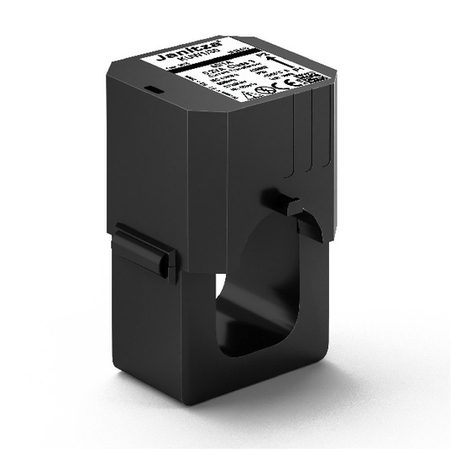
model KM-NCT-E@@@A
Split Type Current Transformer
INSTRUCTION MANUAL
Thank you for purchasing the KM-NCT-E@@@A.
Always need the following points when using the KM-NCT-E@@@A.
• This product is designed for use by qualified personnel with a knowledge of electrical systems.
• Before using the product, thoroughly read and understand this manual to ensure correct use.
• Keep this manual in a safe location so that it is available for reference whenever required.
PRECAUTIONS ON SAFETY
CAUTION Indicates a potentially hazardous situation which, if not avoided, will
result in minor or moderate injury, or there may be property damage.
CAUTION
Property damage may occur due to fire.
Tighten the terminal screws to the specified torques.
After tightening the screw, check that the screw is not loose.
M3 screw : 0.3 N·m
Minor or moderate injury or property damage may occur due to explosion.
Do not use in locations exposed to flammable or explosive gases.
Electric shock may occasionally occur.
During mounting, always work with the power supply turned OFF both the main power
supply and breaker.
Electric shock may occasionally occur.
Be sure to mount to coated wire with at least the basic insulation.
Electric shock may occasionally occur.
Do not touch any of the terminals while the power is being supplied.
Minor electric shock, fire, or malfunction may occasionally occur.
Never disassemble, modify, or repair the product.
EN
OMRON Corporation 2018 All Rights Reserved.
OMRON Corporation
PRECAUTIONS FOR SAFE USE
PRECAUTIONS FOR CORRECT USE
Model KM-NCT-E100A KM-NCT-E250A KM-NCT-E500A
Rated primary current: In 100 A 250 A 500 A
Rated secondary current: Is 1 A
Rated frequency 50/60Hz
Overcurrent withstand
capability (continuous)
1.2 In
Overcurrent withstand
capability (1 sec)
4 In
Output characteristics ±3%FS ±1%FS
Phase error ±180 minutes (1.0 In)
±240 minutes (0.2 In)
±60 minutes (1.0 In)
±90 minutes (0.2 In)
Rated load 1 VA
Insulation resistance 100Mmin. (at DC500V mega) between core and all output terminals
Dielectric strength voltage AC2300V, 1 minute between core and all output terminals
Weight Approx. 170g Approx. 175g Approx. 290g
Maximum wire diameter 24 dia. 24 dia. 36 dia.
Output overvoltage protection Built-in clamp element
Operating temperature and
humidity range
-20 to 55°C, relative humidity: 85% max. with no condensation
Storage temperature and
humidity range
-30 to 90°C, relative humidity: 85% max. with no condensation
Applicable standards * EN61010-1, EN61010-2-030, EN61326-1
Installation environment Overvoltage category and measurement category: II, Pollution level: 2
Wiring diameter Guideline for wiring
length limit
Wiring extension limit value (one-way) (m) =
0.475/conductor resistivity (/m)
0.75 mm2
(AWG18 equivalent) 15m
2.0 mm2
(AWG14 equivalent) 43m
General agreement regarding use
LN
KL
Power side Load side
Breaker Load
CT
警告标示的含义
警告标示
为了确保型号 KM-NCT-E □□□ A (以下简称型号 KM-NCT-E)的安全使用,请务必遵守以下事项。
• 请勿在下列环境中进行本产品的存放、安装、使用。
- 受震动、冲击影响大的环境
- 不稳定且可能掉落或倒塌的场所
- 超出规格规定范围的温湿度环境
- 温湿度变化剧烈,可能结露、结冰的环境
- 户外或是会暴露在阳光直射、风吹雨淋下的环境
- 受静电、噪音影响的环境
- 受电场、磁场影响的环境
- 易浸水、沾油的环境
- 有盐水飞溅的环境
- 有腐蚀性气体 (特别是硫化气体、氨类气体)的环境
- 粉尘、铁粉等多的环境
- 有溶解性液体的环境
• 请确认端子符号后正确排线。请勿在不使用的端子上连接任何电缆。
• 输出端子的配线请使用 AWG18 ~ 14 (断面积 0.75 ~ 2.0mm2)的电线以及适用于 M3 螺钉的 Y 型
端子。
• 输出端子的 M3 螺钉推荐紧固扭矩为 0.3N·m。
• 请勿强力拉伸配线电缆。
• 请在充分理解本使用说明书的基础上,进行使用及维保。
• 将型号 KM-NCT-E 安装于计测电线时,请将扣合卡爪推入至听到 “ 咔嚓 ” 声为止。
• 请勿将本产品安装在靠近发热设备 (含有线圈、绕组的设备等)的位置。
• 使用时请勿超出额定一次侧电流值范围。
• 型号 KM-NCT-E 是型号 KM-N2-FLK、型号 KM-N3-FLK 的专用 CT。请勿用于其他电能监测仪。
• 使用设备前请务必确认接线无误后再接通电源。否则可能会因接线不良而导致触电、受伤、事
故、故障、错误运行的危险。
• 一次侧电线的发热可能会导致 CT 表面温度升高。
通电后,请务必在确认 CT 表面温度已下降后再触碰。
• 本产品并非计量法所规定的指定机构认证合格的特定计量设备。不推荐使用本产品进行电能用量
证明。
• 清洁本产品时,请务必在未通电的状态下,用柔软的干布擦拭产品表面。此外,请勿使用包含稀
释剂、轻汽油、酒精等溶剂成分的药品等。
• 清洁时请勿使用稀释剂类物质。请使用市面销售的酒精进行清洁。
• 本产品为工业环境产品。请勿在住宅环境中使用。
■规格
* 仅限安装于型号 KM-N2-FLK、型号 KM-N3-FLK 上使用时,所装电量监测仪与本产品方为适用规格。
本产品单体非上述适用规格。
* 不支持 UL 规格。
■ 型号 KM-NCT-E □□□ A 上的配线
• CT 输出端子的配线请使用 AWG18 ~ 14 (断面积 0.75 ~ 2.0mm2)的电线以及适用于 M3 螺钉的 Y
型端子。
• 输出端子的 M3 螺钉推荐扭矩为 0.3N·m。请将 Y 型端子插入最深处,然后进行紧固。配线固定
后,请确认是否固定牢固。
• 型号 KM-N2-FLK 或 型号 KM-N3-FLK 与型号 KM-NCT-E 之间的配线长度限值参考值如下所示。如果
配线过长,则会导致型号 KM-NCT-E 上的计测误差增大。
• 配线长度限值还可通过以下公式计算。请在基于所用排线的导电体电阻率算出排线长度限值后,
采用排线长度限值以下的排线长度。
• 下表及通过下述公式算出的配线长度限值均为参考值,并不保证能否正常使用。
■ 计测电线上的安装
为了确保安全,请务必切断主电源及断路器电源,在无通电状态下执行作业。
• 变流器上带有极性。请在确认电源侧 (K)、负荷侧 (L)
的方向后再进行连接。方向一旦接错则无法正确测量。
• 请务必安装于绝缘线上。
• 请勿在二次侧开放状态下接通电源。
* 电能监测仪上的配线方法请分别参阅各使用说明书。
在客户的应用中,欧姆龙不负责产品与任何客户端产品所涉及的规格、规范和标准保持一致性。请务
必考虑本产品对于所应用的系统、机器和设备间的适用性。使用时请注意并遵守本产品的禁止事项。
在没有确认整个系统设计时所考虑到的风险,以及没有确认在设备和系统中该欧姆龙产品的额定使
用条件和正确安装条件的情况下,禁止将本产品应用于对人身及财产存在严重危险的场合。详见产
品规格书中保证及免责事项内容。
KM-NCT-E@@@A
独立型变流器
使用说明书
本次承蒙惠购本产品,谨致谢意。
使用时,请务必遵守以下内容。
• 请由具备电气知识的专业人士进行操作。
• 请在熟读本使用说明书,并充分掌握其内容的前提下,正确使用本产品。
• 请妥善保管本使用说明书,以便随时查阅。
安全注意事项
注意 若不采取正确的使用方法,可能会导致轻伤、中度伤害及财物损失等
后果。
注意
极少数情况下可能会引发起火,导致财物损失。
请务必按照规定的扭矩拧紧端子螺丝。
请确保拧紧螺丝。
M3 螺丝: 0.3 N·m
极少数情况下可能会引发爆炸,可能会导致中度、轻度的人身伤害及财物损失
等后果。
请不要在含有易燃、易爆气体的场所使用本产品。
偶尔会有触电的危险。
安装时请务必切断主电源和断路器后在非通电状态下进行操作。
偶尔会有触电的危险。
请务必安装于达到基本绝缘标准以上的绝缘线上。
极少数情况下存在触电风险。
通电状态下,请勿触摸端子。
极少数情况下可能会导致触电、轻伤、起火、设备故障等后果。
请勿拆卸、修理、改造本产品。
CHN
OMRON Corporation 2018 All Rights Reserved.
欧姆龙公司
安全要点
使用注意事项
型号 型号 KM-NCT-E100A 型号 KM-NCT-E250A 型号 KM-NCT-E500A
额定一次电流:In 100A 250A 500A
额定二次电流:Is 1A
额定频率 50/60Hz
过电流耐量 ( 连续 ) 1.2 In
过电流耐量 (1 秒 ) 4 In
输出特性 ±3%FS ±1%FS
相位差 ±180 分钟 (1.0 In)
±240 分钟 (0.2 In)
±60 分钟 (1.0 In)
±90 分钟 (0.2 In)
额定负荷 1VA
绝缘电阻 100MΩ 异常 (使用 DC500V 兆欧表) 磁芯与所有输出端子之间
耐电压 AC2300V 1 分钟 磁芯与所有输出端子之间
重量 约 170g 约 175g 约 290g
电线最大直径 φ24 φ24 φ36
输出过电压保护 使用内置固定元件
使用温湿度范围 -20 ℃~ +55 ℃ 相对湿度 85%RH 以下 ( 但不得结露 )
保存温湿度范围 -30 ℃~ +90 ℃ 相对湿度 85%RH 以下 ( 但不得结露 )
适用规格 * EN61010-1、EN61010-2-030、EN61326-1
设置环境 过电压分类、测定分类:II、污染度:2
配線径 配线长度参考限值
配线延长限值 (单程)(m)=
0.475/ 导电体电阻率 (Ω/m)
0.75mm2
(相当于 AWG18) 15m
2.0mm2
(相当于 AWG14) 43m
使用时的注意事项
c2013年7月
技术咨询
欧姆龙自动化(中国)有限公司
地址:中国上海市浦东新区银城中路200号
中银大厦2211室
电话:(86)21-5037-2222
技术咨询热线:400-820-4535
网址:http://www.fa.omron.com.cn
KM-NCT-E_EN_SCH.fm 1 ページ 2018年6月12日 火曜日 午後4時47分

