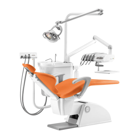
OMS DUKE User manual

DUKE S.T.01/3AR rev.0 4/2011
1
date
R. S. G. Q.
Technical Dir.
General Dir.
21/04/2011
Instruction Manual
DUKE

DUKE S.T.01/3AR rev.0 4/2011
2

DUKE S.T.01/3AR rev.0 4/2011
3
ENGLISH (Translation of original instructions)
1 GENERAL INFORMATION ...................................................................................................................................................................5
1.1 SAFETY RULES ...............................................................................................................................................................................5
1.2 ADMISSIBLE AMBIENT CONDITIONS .............................................................................................................................. 6
1.3 WARRANTY...................................................................................................................................................................................... 7
2 TEChNICAL SPECIFICATIONS ......................................................................................................................................................... 7
2.1 ID PLATE DATA .............................................................................................................................................................................8
3 TECHNICAL INSTRUCTIONS FOR INSTALLATION...............................................................................................................8
3.1 PACKAGING .....................................................................................................................................................................................8
3.2 INSTALLATION............................................................................................................................................................................9
3.3 CONNECTIONS .............................................................................................................................................................................9
3.4 TESTING AND COMMISSIONING ....................................................................................................................................... 9
4 CONTROLS - ADJUSTMENTS –WARNING SIGNS................................................................................................................ 10
4.1 SAFETY SYSTEMS...................................................................................................................................................................... 10
4.2 INSTRUMENT TABLE ............................................................................................................................................................... 10
4.3 DENTAL CHAIR ........................................................................................................................................................................... 12
4.4 FOOT CONTROL.......................................................................................................................................................................... 13
4.5 FLOOR-MOUNTED BOX ........................................................................................................................................................... 13
4.6 SCIALYTIC LAMP........................................................................................................................................................................ 14
5 HIGH SPEED ASPIRATION .............................................................................................................................................................. 14
6 DENTAL CHAIR...................................................................................................................................................................................... 14
6.1 DOUBLE ARTICULATING HEADREST................................................................................................................................. 14
6.2 ARMREST ....................................................................................................................................................................................... 14
7 SCHEDULED MAINTENANCE........................................................................................................................................................... 15
7.1 EXTERNAL CLEANING AND TOUCH-UPS.......................................................................................................................... 15
7.2 DRAINING THE CONDENSATE ............................................................................................................................................ 15
7.3 CLEANING AND MAINTAINING THE INSTRUMENTS.............................................................................................. 15
8 HIGH SPEED ASPIRATION SYSTEM MAINTENANCE.......................................................................................................... 15
8.1 CLEANING OPERATIONS AFTER EACH INTERVENTION ......................................................................................... 15
8.2 DAILY CLEANING AND DISINFECTION.......................................................................................................................... 16
8.3 PERIODIC CLEANING ............................................................................................................................................................... 16
8.4 ANTIFOAM AGENTS................................................................................................................................................................. 16
8.5 CANNULA MAINTENANCE AND REPLACEMENT OF EXTERNAL TUBES............................................................. 16
9 UNSCHEDULED MAINTENANCE .................................................................................................................................................... 16
9.1 REPLACEMENT OF FUSES ....................................................................................................................................................... 16
9.2 ADJUSTMENT OF THE SWINGARM SPRING................................................................................................................. 17
9.3 WATER FILTERS......................................................................................................................................................................... 17
9.4 ADJUSTING THE CLUTCHES ................................................................................................................................................ 17
FORM TO REPORT ACCIDENTS TO PERSONS.............................................................................................................................. 19
WARNING
Before using the equipment, read the O.M.S. instruction manual completely and any instructions supplied with the
accessories.
O.M.S. reserves the right to make changes to its products without prior notice.

DUKE S.T.01/3AR rev.0 4/2011
4

DUKE S.T.01/3AR rev.0 4/2011
5
1 GENERAL INFORMATION
Duke offers a wide range of instruments to be positioned in the four existing housings.
The instrument table is made entirely of porcelain and has no interstices, allowing for easier hygiene.
The arm is fixed to the base of the chair, allowing the table to rotate 270° around the patient for use by right
and left handed operators in a single appliance.
High speed aspiration tubes and connections are easy to remove for disinfection purposes. The filter too can be
extracted in an easy and hygienic manner.
The dental chair was designed to guarantee maximum safety and comfort. The chair back is ultra flat and has no
protruding parts at its bottom, thus enabling the operating staff to be positioned correctly when the patient is
sitting on it. At the same time, it has an anatomic shape that enables the load of the patient’s body to be
distributed in the best and most uniform way possible regardless of his/her size. The chair back can also perform
a compensation movement that prevents irritating pulling of patient’s clothes during the descent phase and
headrest adjustment after this movement.
The backrest is fitted with a safety system which locks all downwards movements in the event of interference
with foreign bodies (e.g. the operator's legs).
1.1 SAFETY RULES
-Warning: To prevent the risk of electrical shocks, the equipment must be connected exclusively to power lines
provided with a grounding system in compliance with the laws in force in the country of use.
-Before powering the equipment after installation, a repair or technical service, check and, if necessary, hook
up the connection of the grounding cables to the screw identified by the grounding system symbol.
-This equipment must be installed in rooms where the existing electrical systems conform to the regulations in
place in the installation country.
-The equipment must be installed by an authorised OMS technician; the choice of piping is made by the
designer of the system and this must be laid by a technician qualified pursuant to the laws in force in the
country of installation.
-Non-professional operators or operators who have not read this instruction manual must not be allowed to
operate the equipment.
-Always make sure that the equipment is in good operating condition.
-Do not operate the equipment if one of its parts is defective or worn. If this is the case, ask for the help of
authorised O.M.S. technicians.
-Replace defective or worn parts using genuine spare parts only that are guaranteed by O.M.S..
-Do not operate the equipment on patients with pacemakers.
-The equipment is not suitable for operation in the presence of a flammable anaesthetic mix of air and oxygen
or nitrous oxide.
-Do not operate the equipment in the event of liquid spillage on the floor.
-Tips and dental drills for micromotors and turbines are not included in O.M.S. supply. We recommend using
parts conforming to the standard ISO 10993-1 that have to be cleaned and sterilised according to the
methods defined by their manufacturers.
-Warning: do not modify this equipment without prior authorisation by the manufacturer.
-Maintenance operations must be performed after switching the equipment off and without a patient sitting in
it.
-Warning: some parts, identified by the symbol illustrated in figure 1 “WARNING – LIVE PARTS”, are
energised with mains voltage even after switching off the power switch. If these parts require service, cut
out voltage to the system supplying power to the equipment, before making any operations.
-Warning: the power switch isolates the equipment from the mains electricity. So, before performing any
operations in the equipment, make sure that the power switch is off.
-To ensure prevention of dental chair movements during specific operations requiring this option, it is
necessary to enable the relevant function (see section 4.3.6 DENTAL CHAIR MOVEMENT STOP).
-Connection to a suction unit must be made in compliance with the instructions given in this manual and in the
wiring diagram; the suction unit must be CE marked pursuant to EC Directive 93/42/EEC and amendments,
“Medical Equipment” and with international safety standards IEC EN 60601-1 (Medical electrical equipment –
General requirements for Safety) and IEC EN 60601-1-2 (Medical electrical equipment –Collateral standard:
Electromagnetic Compatibility).

DUKE S.T.01/3AR rev.0 4/2011
6
1.1.1 DEFINITION OF THE EQUIPMENT INTENDED USE
Dental unit used for treating dental diseases.
This dental unit is designed for professional operators (dentists).
1.1.2 ELECTROMAGNETIC POTENTIAL
The equipment was designed and manufactured in compliance with standard IEC EN 60601-1-2 (Medical electrical
equipment, Collateral standard: Electromagnetic compatibility). For this reason it has a level of immunity and
emissions that does not create dangerous interferences with other equipment conforming to this standard.
Interferences may occur with electrical equipment with a level of emissions and immunity that does not comply
with
the IEC EN 60601-1-2 standard. If this is the case, do not operate this equipment simultaneously with O.M.S.
equipment. If the equipment gets stuck due to these interferences, switch it off and on again to restore
operation.
1.1.3 DISPOSAL OF THE EQUIPMENT AT END OF OPERATING LIFE
European Directives 2002/96/EC and 2003/108/EC on Waste Electric and Electronic Equipment (WEEE).
The symbol showing the crossed out bin (see figure 3) affixed on the equipment or packaging means that the
product must be disposed of separately from other waste at the end of its operating life. The user, therefore,
must take the equipment to suitable centres for separate collection of electronic and electrical waste;
alternatively, the equipment must be given to the dealer where new equivalent equipment is purchased on a one-to-
one basis.
Proper separate collection of waste for further recycling, treatment and disposal in a compatible environment
prevents possible negative effects on the environment and health and contributes to the re-use and/or recycling
of the materials which are comprised in the equipment.
ADDITIONAL INFORMATION FOR ITALY
Reference legislation: art. 13 of the Italian Legislative Decree no. 151 of 25 July 2005 “Implementation of
European Directives 2002/95/EC, 2002/96/EC and 2003/108/EC on the reduced use of hazardous substances in
electric and electronic equipment and disposal of waste”.
Pursuant to the legislation above, professional users (companies or institutions) must organise and manage
separate collection of the equipment at the end of its operating life as follows:
a) directly, whenever the user decides to get rid of the equipment without replacing it with a new equivalent
equipment to be used for the same purposes;
b) through the manufacturer, i.e. the person who has firstly marketed and sold the product in Italy or sells the
new replacement equipment under his own brand in Italy. In this case, of course, the user must have decided
to get rid of the obsolete equipment and to purchase an equivalent product to be used for the same purposes.
In this case, the user can request the manufacturer to take back the obsolete equipment by and within 15
consecutive calendar days after the delivery of the new equipment.
Unauthorised disposal of the equipment by the user is punished by the existing law with the application of specific
sanctions.
1.2 ADMISSIBLE AMBIENT CONDITIONS
1.2.1 ADMISSIBLE AMBIENT CONDITIONS FOR TRANSPORTATION AND STORAGE
The packed equipment can be exposed to the following ambient conditions for a time not exceeding 15 weeks:
Temperature range: -40 to +70°C
Relative humidity range: 10 to 100% non condensing
Atmospheric pressure range: 500 to 1060 hPa
1.2.2 ADMISSIBLE AMBIENT CONDITIONS FOR OPERATION
Temperature range: +10 to +40°C
Relative humidity range: 30 to 75%
Atmospheric pressure range: 800 to 1060 hPa
Nominal operating altitude: ≤ 2000m

DUKE S.T.01/3AR rev.0 4/2011
7
1.3 WARRANTY
O.M.S. guarantees its products for a maximum period of three years from the installation date. When the
equipment is installed, it is essential to fill in the warranty form enclosed with the equipment documentation.
After the warranty form has been filled out, it must be sent to the following address within the next 10 days:
O.M.S. S.p.A. Via Dante 20/A - 35030 CASELLE DI SELVAZZANO (PADOVA) –ITALY
Remember to keep the first page.
N.B.: all products not manufactured by O.M.S. (e.g. handpieces, turbines, suction devices, etc.) the warranty terms
offered by their respective manufacturers apply. In this case too, however, the warranty form must be returned.
2 TECHNICAL SPECIFICATIONS
Model DUKE
Manufactured by O.M.S. S.p.A. Officine Meccaniche Specializzate
Via Dante 20/A - 35030 Caselle di Selvazzano, Padova, Italy
Class I
Applied parts type B
Equipment protection level IPX0
Foot control protection level IPX1
POWER SUPPLY
Nominal voltage 230 Vac +/-10%
Nominal current 8 A (4.5 A equipment + 3.5 A aspiration pump output)
Nominal output 1800 W (1000 W equipment + 800 W pump
output)
Rated frequency 50 Hz
Max. internal voltage 35 Vdc, 25 Vac (downline of the safety transformer)
230Vac dental chair motors
Network connection through conductors that comply with the regulations existing in
the installation country.
HYDRO-PNEUMATIC SUPPLIES
Pneumatic supply from 450 kPa to 650 kPa (from 4.5 to 6.5 bar)
(consumption of aspirated air equalling approx. 40 litres/minute)
Water supply from 200 kPa to 400 kPa (from 2 to 4 bar)
(consumption of water equalling approx. 2 litres/minute)
Max. temperature 30 °C
OPERATING TIMES
Chair intermittent 1’ on / 10’ off
Syringe 6F (hot water) intermittent 5’ on / 10’ off
Polymerization lamp intermittent 20”on / 3’ off
Tooth scaler (with water) intermittent 3’ on / 5’ off
Micromotor intermittent 3’ on / 3’ off
Operating lamp continuous
Syringe 3F (cold water) continuous
EDI OPERATING LAMP (with cooling fan)
Power voltage: 17 Vac
Halogen lamp: 17 V, 95 W
Colour temperature: 5000 °K
Focal distance: 700 mm
Operating field (at 700 mm): 60x180 mm
Max. luminous intensity (at 700 mm): 25000 Lux.
GCOMM POLARIS LAMP
Power voltage: 17-24 Vac
Colour temperature: 4200-6000 °K
Focal distance: 700 mm
Operating field (at 700 mm): 70x140 mm

DUKE S.T.01/3AR rev.0 4/2011
8
Light intensity: 15000-30000 Lux.
MISCELLANEOUS
Total weight approx. 165 Kg
Dimensions (see figure 19)
Max. load allowed on dental chair 135 kg
Length of foot control cable 2.5 m
Min. space recommended for
equipment installation area approx. 3.20x3.00x3.00 m (LxHxD)
IMPORTANT
The apparatus is designed and constructed in compliance with directive 93/42/EEC and amendments, “Medical
Equipment” and with international safety standards IEC EN 60601-1 (Medical electrical equipment –General
requirements for Safety) and IEC EN 60601-1-2 (Medical electrical equipment –Collateral standard:
Electromagnetic compatibility), ISO 7494-1 (Dental units - General requirements and test methods) and ISO
6875 (Dental patient chair).
O.M.S. declines any and all responsibility for equipment safety and reliability in the following cases: if installation,
additions, re-calibration, modifications or changes are not performed by O.M.S. authorised technicians following
the instructions and using the components supplied by O.M.S. exclusively; if the electric system installed in the
workplace does not comply with IEC standards; and/or if the equipment is not used according to the operating
instructions.
2.1 ID PLATE DATA
The dental chair support features an ID plate located under the seat that shows the general data of the
equipment (see Figure 4).
B. Manufacturer
C. Rated voltage and current type (alternating )
D. Rated frequency
E. Rated current
F. Rated power
G. Equipment model
H. Cooling fluid temperature
I. Applied part, type B
J. Medical equipment directive 93/42/EEC and amendments
K. Warning: consult the annexed documentation (operating instructions).
L. Equipment serial number
3 TECHNICAL INSTRUCTIONS FOR INSTALLATION
3.1 PACKAGING
The equipment is shipped in a crate which also contains a box of accessories, instruction manual S.T. 01/3, wiring
diagrams, lamp*, lamp arm*, suction unit*, fixing screws.
(*) Supplied only if specifically requested in the purchase order.
Outside each crate a tag shows the purchase order number, the order acknowledgement number and the
equipment model.
N.B.: if an O.M.S. stool is included in the supply, this is packed separately.

DUKE S.T.01/3AR rev.0 4/2011
9
3.2 INSTALLATION
1. Remove the equipment from its packaging.
2. position the chair on the markings made previously using the installation diagram and turn the adjustment
feet correctly to set possible “gaps”. Secure the dental chair to the floor using the two supplied expansion
screws.
3. If an operating lamp is featured, install it and connect it to the electric mains.
4. Check and, if necessary, hook up the connection of the grounding cables to the screw identified by the
grounding system symbol.
5. to connect the suction pump (see wiring diagram) use the same methods described in the following point for
the power cables (fixing the cables and traction).
6. remove the guard at the base of the chair, unscrewing screws D (in figure 02), to connect the water and air
(see para. 3.3 CONNECTIONS), the suction, the drainage and finally the electricity (mains connection clamp);
the power cables on the mains terminal board must be fixed using nylon clamps to the punched insulation
board under the clamp, in particular it must be guaranteed that, in the event of a fixing device (clamp)
breaking, the protection wire is not subject to traction while the mains wires are still connected to the clamp;
7. Fit the accessories (instruments), if any, on the instrument and dental assistant tables.
N.B. : For all electric connections refer to the enclosed electric and installation diagram.
3.3 CONNECTIONS
First of all make sure that the air and water flows from the water and pneumatic supplies are regular. O.M.S.
declines all liability for malfunctions or damage caused by the non-compliance with the following warning:
Water supply:
water with a medium/low content of salt (fit a water softening device, if necessary) to be connected to the
transparent pipe, 6x8 mm in diameter (see chapter 2 TECHNICAL SPECIFICATIONS for the allowed pressure).
Pneumatic supply:
compressed air, preferably dehumidified and oil-suspension-free, to be connected to the light blue pipe, 4x6 mm
in diameter (see chapter 2 TECHNICAL SPECIFICATIONS for the allowed pressure).
We recommend making a temporary direct connection between the water delivery pipe and the drain pipe, and
letting the water circulate for a few seconds before installing the equipment. This enables elimination of any
impurities from the tubes.
3.4 TESTING AND COMMISSIONING
IMPORTANT WARNING
During testing, check the mechanical stability of the equipment after placing all the mobile elements and
accessories (table, lamp, etc.) in the most unsuitable position possible.
1. Check the correct position of the tray holder table: if an unusual tilting is identified, adjust the table using
the screw (detail A in Figure 15) located inside the front part of the arm.
2. Check that the manual controls for the rise and descent of the pantographic arm and chair back, the
automatic reset, the rinsing position and return to the work position (last position control) controls work
correctly. Check and store correct positioning of the programme (see sections 4.3.1 MANUAL CONTROLS and
4.3.2 AUTOMATIC CONTROLS).
3. Check that the limit switches and safety devices work correctly (see section 4.1 SAFETY SYSTEMS).
4. Check correct calibration of the pressure regulators and general flow regulators and that of each instrument.
These devices have already been calibrated by O.M.S. in the workshop, but they may require an inspection or
re-calibration.
NOTE: we recommend closing the general water tap whenever leaving the dental surgery in order to prevent
flooding due to accidental system breakages.
WARNING: before performing any operations in the equipment, always make sure that the power switch is off.

DUKE S.T.01/3AR rev.0 4/2011
10
4 CONTROLS - ADJUSTMENTS –WARNING SIGNS
4.1 SAFETY SYSTEMS
The dental chair is supplied with safety devices which minimise the risk of crushing or collision with underlying
objects during chair descent. Safety devices include a special sensor on the dental chair back, an electric and
mechanical safety device installed at the base of the dental chair back.
Whenever the sensor installed on the dental chair back is engaged during a descent movement (either of the
pantographic arm or chair back), the part moving down stops. A warning LED at the bottom of the seat (detail B in
Figure 5) goes ON and stays ON until the obstacle causing safety device engagement is cleared. To perform the
required movement, remove the obstacle and repeat the control.
The sensor installed on the back of the dental chair is calibrated as instructed below.
-Place the dental chair in its final position.
-Put a screwdriver in the hole for the calibration of the sensor located at the bottom of the chair seat (detail
B in Figure 5). Turn the screwdriver clockwise to reduce the sensor sensitivity and anticlockwise to increase
it.
-Control the pantographic arm or chair back to move downwards and touch the back of the dental chair to
engage the safety sensor (detail A in Figure 5) in order to check its sensitivity. Repeat the operations from
the previous item until the ideal sensor sensitivity is found.
When the back safety sensor is engaged, all downward movements of both the back and pantographic arm are
disabled.
The back of the dental chair is also provided with an electric and mechanical safety device which stops the
descent movements of both the pantographic arm and back whenever obstacles are present in the outreach of the
keyboard. Whenever this safety device is engaged, all downward movements of both the pantographic arm and
back are disabled.
During automatic movements of the dental chair (position reset, memorised positions or rinsing positions), press
any control of the dental chair (on the pushbutton panels of the dental unit or foot control) to immediately stop
the dental chair.
When switched on and during normal use, the chair movement may be hindered if one or more of the safety
systems are active.
4.2 INSTRUMENT TABLE
The instrument table can house four instruments (including a syringe and any aspiration cannulas) and has three
sectors.
The first sector includes the instrument unit controls and options, if any. The general board for dental unit
operation is installed here along with all the electrical connections of the instruments.
The second sector includes the instrument solenoid valve unit where all the adjustment devices are well visible. A
description of the function of each device is provided in the instrument module chapters. Adjustments that are
not equipped with a handle must be made by authorised O.M.S. technicians.
The third sector is the portion of the table where instruments are positioned.
4.2.1 PUSHBUTTON PANEL
Controls (see Figure 7) are completely membrane sealed. This enables higher operating safety and elimination of
the interstices, and makes the surface sanitizable.
The functions of the buttons are:
A. Assistant request
B. Storage of chair programme (by pressing the button for 3 seconds)
C. Optic fibre lighting pre-selection control
D. Optic fibre lighting pre-selection LED
E. Spray pre-selection control
F. Spray pre-selection LED
G. Power LED (power on)
H. Reset position call-up control
I. dental chair back rise (up) control;
L. dental chair pantographic arm rise (up) control;

DUKE S.T.01/3AR rev.0 4/2011
11
M. dental chair pantographic arm descent (down) control;
N. dental chair back descent (down) control;
O. dental chair rinsing/last position control;
4.2.2 TURBINE MODULE
The turbine operates when the instrument is lifted from its housing and moved towards the operating field, and
when the foot control is engaged (see section 4.4.1 TURBINE OPERATION).
When the instrument is lifted from the table, all the other dynamic instruments and the dental chair movements
are disabled.
Upon request, the turbine fitted can be variable (option), i.e. it has a variable rotation speed depending on the
position of the foot control lever.
The spray is always pre-selected. The water delivered to the spray is regulated by opening/closing the tap located
near the instrument under the turbine module. When the tap is rotated clockwise, the flow of water to the spray
decreases until it stops; when turned anticlockwise, the opposite occurs. We recommend not using other regulation
devices located alongside the spray tap.
If the system is equipped with an optic fibre lighting system, the lights go on when the control “N” installed in the
table pushbutton panel is engaged (when this function is enabled, it has an impact on all the instruments). The
enabled function is shown by LED (D) coming on.
The recommended air pressure (measured during turbine operation) is set during testing operations at O.M.S.
Check the pressure calibration again when the equipment is installed using a gauge and make sure that the
pressure values indicated by the turbine manufacturer are met. This operation must be performed by an
authorised O.M.S. technician.
For further details refer to the manufacturer’s operating instructions enclosed.
4.2.3 ELECTRIC MICROMOTOR MODULE
The micromotor operates when the instrument is lifted from its housing and moved towards the operating field,
and when the foot control is engaged (see section 4.4.2 MICROMOTOR OPERATION).
When the instrument is lifted from the table, all the other dynamic instruments and the dental chair movements
are disabled.
The micromotor can work at variable rpm, from a minimum of approx. 900 rpm to max. 40,000 rpm.
Usually, the micromotor rotates clockwise. To invert the direction of rotation
move the foot control lever to the left, push and release. An acoustic warning signal (beep)
indicates that the function is active. The function is also shown on the display with a change in the arrow
direction.
When the foot control lever is moved to the left again, the initial condition is restored and the
buzzer (beep) is silenced.
It is advised to invert the direction of rotation only with the motor at a standstill, to prevent damage.
The spray is pre-selected by pressing (E); the enabled function is shown by the LED (F) coming on. Also see
section 4.4.2 MICROMOTOR OPERATION.
The water delivered to the spray is regulated by opening/closing the tap located under the micromotor module:
when turned anticlockwise, the flow of water to the spray is gradually reduced; when turned clockwise, the
opposite occurs. We recommend not using other regulation devices located alongside the spray tap.
If the system is equipped with an optic fibre lighting system, the lights go on when the control “N” installed in the
table pushbutton panel is engaged (when this function is enabled, it has an impact on all the instruments). The
enabled function is shown by LED (D) coming on.

DUKE S.T.01/3AR rev.0 4/2011
12
4.2.4 TOOTH SCALER MODULE
The tooth scaler operates when the instrument is lifted from its housing and moved towards the operating field,
and when the foot control is engaged (see section 4.4.3 TOOTH SCALER OPERATION).
When the instrument is lifted from the table, all the other dynamic instruments and the dental chair movements
are disabled.
The water delivered to the spray is regulated by opening/closing the tap located under the tooth scaler module:
when turned anticlockwise, the flow of water to the spray is gradually reduced; when turned clockwise, the
opposite applies.
If the system is equipped with an optic fibre lighting system, the lights go on when the control “N” installed in the
table pushbutton panel is engaged (when this function is enabled, it has an impact on all the instruments). The
enabled function is shown by LED (D) coming on.
For further details refer to the manufacturer’s operating instructions enclosed.
4.2.5 SYRINGE MODULE
The syringe operates at any time by simply pressing one of the two levers enabling either water or air supply
(left-hand lever for water and right-hand lever for air). When these two supply buttons are pressed
simultaneously, spray water is delivered.
For further details refer to the manufacturer’s operating instructions enclosed.
4.3 DENTAL CHAIR
4.3.1 MANUAL CONTROLS
The dental chair movements can be activated from the instrument table, the foot control (see section 4.4.4
DENTAL CHAIR CONTROLS FROM FOOT CONTROL).
4.3.2 AUTOMATIC CONTROLS
The dental chair is supplied with controls that activate 1 storable and editable programme for automatic reset
(programmable), rinsing position and return to the last work position (last position).
4.3.3 STORING THE PROGRAMME
Place the chair in the required position and then hold down button (B) (see figure 7) for at least 3 seconds, until
the acoustic signal is given to signal storage (beep).
4.3.4 CALLING UP THE RESET POSITION AND PROGRAMME
The reset position is called by pressing A in figure 6.
The programmed position is called by pressing B in figure 6.
4.3.5 STORING THE RESET POSITION
The chair can store the best reset position; on installation there is a default reset position stored by O.M.S..
To modify this position, proceed as follows:
-call up the stored reset position;
-choose a new reset position manually (see para. 4.2.1 PUSHBUTTON PANEL and para. 4.3.1 MANUAL
CONTROLS);
-store the new position by holding down H (see figure 7) until an acoustic signal is given to confirm storage
(beep).
IMPORTANT: The reset position can be stored only in the safety area, signalled during pantographic arm descent,
by an intermittent acoustic signal (beep). The memory stores only the pantographic arm position, while the
backrest position remains the same.
4.3.6 DENTAL CHAIR MOVEMENT STOP
Some operations may require a stop of the dental chair movements to prevent accidental engagement of the chair
caused either by operators or other events.
The foot control lever (A) (see figure 8), positioned with light pressure to the left (position A1), excludes all chair
movements, allowing the operator to carry out all operations without dynamic instruments on the patient and
without the risk of any accidental movement of the chair.

DUKE S.T.01/3AR rev.0 4/2011
13
4.4 FOOT CONTROL
The equipment foot control (see Figure 8) was designed to control all the possible functions of the instruments
with a simple movement of the lever (A).
N.B.: when the instrument is extracted, it is automatically connected to the foot control, thus disabling all the
other instruments even at a subsequent extraction (by the dental assistant, for instance).
4.4.1 TURBINE OPERATION
Having extracted the instrument from its housing:
- press the lever A of the foot control to engage the chip-blower control;
- move the lever A to the right to operate the instrument. If lever A is pressed simultaneously, the turbine is
sprayed.
4.4.2 MICROMOTOR OPERATION
Having extracted the instrument from its housing:
- press the lever A of the foot control to engage the chip-blower control;
- move the lever A to the right to operate the instrument. The spray is pre-selected in the instrument table by
engaging the control D. Then, spray delivery is possible when the foot control lever (A) is slightly pressed with the
instrument in operation (standard configuration). Upon request, the technician can modify the connection during
installation so that the spray is delivered without pressing the lever.
4.4.3 TOOTH SCALER OPERATION
Extract the instrument from its housing and move the lever (A) to the right to operate the instrument. The spray
is pre-selected in the instrument table by engaging the control D. Then, spray delivery is possible when the foot
control lever (A) is slightly pressed with the instrument in operation (standard configuration). Upon request, the
technician can modify the connection during installation so that the spray is delivered without pressing the lever.
4.4.4 DENTAL CHAIR CONTROLS FROM FOOT CONTROL
The foot control is equipped with two side levers (see Figure 8, det. B and C) that are operated to position the
dental chair using foot controls:
-move the lever (B) to the right to lift the pantographic arm;
-move the lever (B) downwards to start lowering the pantographic arm;
-move the lever (C) upwards to start lowering the dental chair back;
-move the lever (C) downwards to start lifting the dental chair back.
4.5 FLOOR-MOUNTED BOX
The floor box contains all the electrical, water and pneumatic control systems of the dental chair.
This box is designed to connect the dental unit to the electric mains, water mains, drain, compressed air mains and
the pipe coming from the surgical aspiration motor, if fitted.
Access to the column is gained by unscrewing the screws D (in figure 02) and removing the plastic guard C, after
cutting out voltage (as instructed in section 1.1 SAFETY RULES).
4.5.1 AIR PRESSURE REGULATOR
The air pressure regulator is used to keep the air pressure of the instrument in the table constant.
The regulator is calibrated during the testing phase at O.M.S. and calibration can be changed exclusively for
technical reasons. This operation must be performed by an authorised technician.
The regulator collects any condensate present in the compressed air. For condensate draining refer to paragraph
7.2 CONDENSATE DRAINAGE.
4.5.2 WATER PRESSURE REGULATOR
The water pressure regulator is used to keep the water pressure of the instrument in the table constant. The
regulator is calibrated during the testing phase at O.M.S. and calibration can be changed exclusively for technical
reasons. This operation must be performed by an authorised technician.
The regulator has a filter that must be checked periodically and replaced, if necessary, as described in paragraph
9.3 WATER FILTERS.

DUKE S.T.01/3AR rev.0 4/2011
14
4.6 SCIALYTIC LAMP
Only two operations are possible with this lamp:
- switch on / off;
- adjustment of brightness.
O.M.S. dental units are prepared for fitting EDI OPERATING LAMPS (with cooling fan).
For further details refer to the manufacturer’s operating instructions enclosed.
5 HIGH SPEED ASPIRATION
The equipment can be connected to a high speed air ring, liquid ring or ecological liquid ring type aspiration system.
The aspiration cannulas are housed in the instrument table.
The aspiration system consists of the following parts (see Figure 9):
A. a drain (located under the instrument table);
B. a filter;
C. a drain plug;
D. 2 aspiration tubes, approx. 1.5 m in length and 11 and 16 mm in diameter;
E. aspiration end pieces, 11 and 16 mm in diameter.
Given that the equipment cannot house other suction or separation systems, the external aspiration system must
be fitted with a separator (e.g. amalgam) and if suction is centralised also a shutter solenoid valve must also be
fitted to select the work station.
6 DENTAL CHAIR
The dental chair can be fitted with a double articulating headrest.
6.1 DOUBLE ARTICULATING HEADREST
The height of the double articulating headrest (figure 10) can be adjusted to a max. travel of 23 cm. This part
has two articulations that can be controlled simultaneously by means of a lever placed on its back (A). The lever
enables easy movement of the headset on the two rotation axis (B).
When the headrest pillow is tilted to approx. 90° with respect to the articulation mechanism (C), it can perform a
180° rotation on its axis (D). The articulation mechanism can also be lowered to a position that makes the headrest
more comfortable for short patients (E).
6.2 ARMREST
The dental chair is supplied with one armrest on the left-hand side. The movement of the armrest is synchronised
with the movement of the chair back. Upon request, the dental chair can be supplied with both armrests (option)
whose movement is synchronised with that of the chair back. The right-hand side armrest features a button (at
its base) which, when pressed, enables to lower the armrest frontally or backwardly for easier patient’s passage.
When lowered backwardly, the armrest can be easily removed by slightly rotating it to pull it in the rotation axis
direction. Perform these operations in reverse order to put it back in place after removal and ensure that the
armrest is all the way down in its seat before turning it.
The operations required to remove and install the armrest must be performed gently without forcing any
movement especially if difficulties are experienced.

DUKE S.T.01/3AR rev.0 4/2011
15
7 SCHEDULED MAINTENANCE
Below is a description of some scheduled maintenance operations that we recommend performing following the
instructions provided and intervals indicated in order to guarantee maximum equipment efficiency over time.
For damage-free equipment hygiene and cleaning O.M.S. also recommends using products
that contain:
-quaternary ammonia;
-phenolic compounds;
-iodophors;
and that do not contain:
-alcohol;
-hypochlorite.
O.M.S. recommends the products below because they were tested at our premises:
-ZETA 4
-OROLIN ASEPTIK
-OROCID MULTISEPT
-GREEN & CLEAN SK
Upon customer’s request, O.M.S. shall supply a cleaning product that was experimented and tested at our
premises.
O.M.S. declines any and all responsibility for problems originating from utilisation of products other than those
recommended.
7.1 EXTERNAL CLEANING AND TOUCH-UPS
Clean the equipment frequently to preserve its hygienic conditions and prevent prolonged exposition of its
surfaces to spots of corrosive substances. We recommend not using methylated spirit and soda or organic-
solvent-based detergents because they may damage the paint and upholstery.
If the enamel is slightly scratched, touch it up with a bottle of colour supplied in the accessory box for this
purpose. We recommend shaking the bottle and mixing the product before using it by repeatedly lifting and
lowering the paintbrush in the enamel bottle. Touch up by “dotting” the damaged area with drops of colour.
7.2 DRAINING THE CONDENSATE
The equipment is supplied with an air filtering device and a condensate drain valve.
Any condensate accumulating in the transparent cup is expelled by pushing upwards the needle valve located on
the cup bottom, as shown in figure 11.
N.B.: check for condensate on a weekly basis.
7.3 CLEANING AND MAINTAINING THE INSTRUMENTS
For instrument cleaning, sterilization and lubrication, we recommend consulting the instructions supplied by the
manufacturer(s) for each model that are attached to this manual and added to the equipment packaging.
8 HIGH SPEED ASPIRATION SYSTEM MAINTENANCE
The best performance is obtained from your high speed aspiration system if the simple operating and maintenance
instructions below are strictly adhered to. Failure to comply with these instructions would jeopardise the
performance of the aspirator performance, sometimes with serious consequences.
8.1 CLEANING OPERATIONS AFTER EACH INTERVENTION
After each intervention, we recommend aspirating clean water for a few seconds in order to rinse the tubing.
Dental tips must be thoroughly cleaned and sterilised. We recommend brushing the cannulas both inside and
outside using the supplied pigs (to be found in the “aspiration system accessory kit”) and a suitable detergent.
Aspiration end pieces supplied by O.M.S. can be autoclaved at a temperature of 130°C.

DUKE S.T.01/3AR rev.0 4/2011
16
8.2 DAILY CLEANING AND DISINFECTION
In order for the aspirated deposits not to clog the filter and corresponding aspiration tubing the following
washing cycle must be carried out at the end of each working day.
For this operation use the products recommended by the aspiration system manufacturers.
1. Use one of the two aspiration cannulas to aspirate the amount of solution indicated in the bottle making sure
that only the cannula end is introduced into the bottle.
2. Let the aspirator run for 3 to 4 minutes, then stop it. Drain the liquid and repeat the previous operation with
the other cannula. Aspirate using one cannula at a time so that the other cannula can be used for air suction,
thus preventing the aspiration system from getting blocked due to an excessive aspiration of liquid.
3. Unscrew the drain plug and clean the filter inside the drain. Replace it, if necessary. Periodically grease the
drain and plug mouthpiece with vaseline, because disinfectants may stiffen these parts, thus making plug
extraction difficult.
Do not mix detergents having different features.
Never immerse aspiration tubes if they do not fit the required cannula.
8.3 PERIODIC CLEANING
Every 30 days of operation (and especially in the event of system inactivity for several days) check the entire
aspiration system and make sure that it works correctly. This check must be performed by an authorised
technician.
8.4 ANTIFOAM AGENTS
If foam-generating substances are used (e.g. hydrogen peroxide, etc.), the system may temporarily stop. If this
malfunctioning occurs, use “antifoam agent” tablets. These tablets (a sample of which is included in the aspiration
accessory kit) must be placed in the drain filter and usually last a few days of operation.
8.5 CANNULA MAINTENANCE AND REPLACEMENT OF EXTERNAL TUBES
All the parts of the aspiration cannulas are easy to disassemble (see Figure 12) for disinfection and cold
sterilization.
Every 15 days spray the closing tabs of each cannula with silicon spray. Spray the end piece inside when the tab is
closed, and the outside when the tab is open. Then, open and close each end piece repeatedly.
For functional and hygienic reasons we recommend replacing the external aspiration tubes and end pieces at least
once a year.
9 UNSCHEDULED MAINTENANCE
Below is a description of some unscheduled maintenance operations. A part from the adjustment of the clutches
and replacement of the fuses that are accessed from the equipment outside, we recommend that all unscheduled
maintenance operations be performed by authorised O.M.S. technicians.
9.1 REPLACEMENT OF FUSES
WARNING: Before replacing a fuse, identify why it blew. Only after removing these causes, replace the fuse. The
new safety fuse must have the same features as the replaced fuse. These specifications are shown in the
electrical diagram of the equipment.
The main safety fuse (detail B in figure 2) is positioned at the base of the chair where it is easy to identify. It
can be replaced from the outside with the help of a screwdriver. Before replacing this fuse, ensure that the
power switch (detail A in figure 2) is off. The fuse must be replaced only after the cause of its tripping has been
cleared. If the problem persists after fuse replacement, we recommend asking for service by an authorised
O.M.S. technician.
Safety fuses are installed on the electronic boards (figure 13, figure 14);
The fuses installed on the electronic boards (positioned inside the guard on the chair base) must be replaced by
an authorised O.M.S. technician.
Below is an indicative list of the values required for the main fuses installed in the equipment:
(Figure 2)
B. general fuse 8AT, 230 Vac
(Figure 13)

DUKE S.T.01/3AR rev.0 4/2011
17
A. operating lamp 6.3AT, 16 or 22.8 Vac;
B. micromotor, progressive turbine, tooth scaler, instrument table solenoids 6.3AT, 28 Vdc;
C. cup heater, amalgam separator and water unit solenoids 6.3AT, 24 Vac;
D. syringes, polymerizing lamp 6.3AT, 24 Vac;
E. dental chair motors 5AT, 230 Vac;
F. primary transformer fuse 4AT, 230 Vac;
G. aspiration system output OUT 5AT, 230 Vac;
H. board and bus power supply 24VS 8AT, 28 Vac.
(Figure 14)
A. 6.3 AF (rapid) for dental chair motors (230 Vac)
B. 1AT electronic board power supply
Spare fuses supplied by O.M.S. are packed in the accessory box.
9.2 ADJUSTMENT OF THE SWINGARM SPRING
The strength of the table-holding arm can be regulated by means of an adjustable spring (see B in figure 15). This
device perfectly offsets the weight of the table, which changes according to the load. This adjustment must be
performed by an authorised O.M.S. technician.
9.3 WATER FILTERS
9.3.2 CLEANING THE WATER FILTER TO THE INSTRUMENTS
To prevent impurities that are always present in the water mains from jeopardising instrument operation, the
water flows through a filtering pad located near the water pressure regulator (see Figure 16).
Every 12 to 24 months ask a technician to check the filter for possible clogging during the periodic overhaul.
Replace the bronze sintered pad, if necessary.
9.4 ADJUSTING THE CLUTCHES
Rotating and pivoting movements can be adjusted so as to obtain the desired friction level for each of them:
-swingarm movement (for tray holder table oscillation) (see figure 17)
-rotation of fixed instrument table arm (see B in figure 18)
-rotation of instrument table (see A in figure 18)
-rotation of tray holder table arm (see C in figure 18)
-rotation of tray holder table (see D in figure 18)

DUKE S.T.01/3AR rev.0 4/2011
18

DUKE S.T.01/3AR rev.0 4/2011
19
FORM TO REPORT ACCIDENTS TO PERSONS
Dir. 93/42/EEC and amendments Ann. II (D.G. 2/1 Rev. 0)
CUSTOMER NAME:___________________________________________________________________
ADDRESS __________________________________________________________________________
EQUIPMENT SERIAL NUMBER__________________________________________________________
DESCRIPTION OF THE ACCIDENT_______________________________________________________
_________________________________________________________________________________
_________________________________________________________________________________
DAMAGE CAUSED TO THE PATIENT’S OR USER’S HEALTH____________________________________
_________________________________________________________________________________
_________________________________________________________________________________
Date _______________________________
Signature ___________________________
AREA RESERVED FOR THE COMPANY (QUALITY ASSURANCE)
POSSIBLE CAUSES OF THE ACCIDENT:
Equipment malfunctioning
Deterioration of equipment features and/or performance
Poor instructions for use
Other causes________________________________________________________________________
SEVERITY OF THE DAMAGE ___________________________________________________________
OPERATIVE DECISIONS PROPOSED _____________________________________________________
Date _______________________________
Signature ___________________________
AREA RESERVED TO THE COMPANY (GENERAL MANAGEMENT)
OPERATIVE DECISIONS ______________________________________________________________
_________________________________________________________________________________
_________________________________________________________________________________
CORRECTIVE ACTIONS _______________________________________________________________
_________________________________________________________________________________
_________________________________________________________________________________
Date _______________________________
Signature ___________________________
In the event of an accident send the form to O.M.S. S.p.A. promptly.

Table of contents
Other OMS Dental Equipment manuals
Popular Dental Equipment manuals by other brands

NSK
NSK S-Max M65 Operation manual

Aseptico
Aseptico ALU-40TC Operation and maintenance instruction manual

dentalfarm
dentalfarm MICRA Evoluzione User and maintenance manual

DENTSPLY
DENTSPLY thermaprep 2 Directions for use

Zhermack
Zhermack hurrimix 2 user manual

Dabi Atlante
Dabi Atlante Bellagio owner's manual