OMS Airstream Evoque Regulator User manual

OWNER GUIDE
OMS Airstream Evoque
Regulator
Intermediate pressure Ref: 140 psi. +/- 5psi
(Yoke supply pressure: 3500 psi)
(Din supply pressure: 4500 psi)
Inhalation Resistance: 0.8 (Column inches of water)
Flow rate: 30+sCFM (air supply: 3000 psi)
Air flow…. 33 cu. ft. (935 liters/min). @ 1 atmosphere
Recommended lubricant LTI Christo-Lube MCG129

2
COPYRIGHT NOTICE©
This owner’s manual is copyrighted(©) OMS 2017. All Rights Reserved. It may not, in whole
or part, be copied, photocopied, reproduced, translated, or reduced to any electronic
medium or machine readable form without prior consent in writing from Ocean Management
Systems (OMS).
Regulator Owner’s Guide, -rev. 2017/04
Warning, Cautions and Notes
Pay special attention to items marked with the warnings, cautions, and notes that are
accompanied by these symbols:
WARNING indicates a procedure or situation that, if not avoided, could result in
serious injury or death to the user.
CAUTION indicates any situation or technique that could cause damage to the
product, and could subsequently result in injury to the user.
NOTE is used to emphasize important points, tips, and reminders.
PRECAUTIONS & WARNING
Before using this regulator, you must have successfully received training and certification in
the technique of SCUBA diving from a recognized certification agency.
Use of SCUBA equipment by uncertified, or untrained persons, is dangerous and can result
in serious injury, or death.
It must not be used by untrained persons who may not have knowledge of the potential risk
and hazards of scuba diving.
This regulator is not configured for commercial use with surface supplied air.
This regulator must be used together with a Submersible Pressure Gauge that measures
and indicates the user’s air supply pressure.
Always pressurize the regulator gradually by opening the cylinder valve SLOWLY.

3
DO NOT apply any type of aerosol spray on the regulator. Doing so may cause permanent
damage to certain plastic components, including the regulator second stage housing.
Factory prescribed service for this regulator must be performed at least once annually by a
specially trained and authorized technician who services OMS SCUBA equipment.
DO NOT leave a cylinder standing unsecured with the regulator attached to the
valve.Doing so may cause permanent damage to the regulator and cylinder valve if the
cylinder falls over against the regulator first stage
DO NOT use the regulator first stage as a carrying handle when lifting or transporting the
cylinder.
It must not be used by untrained persons or persons that do not have knowledge of the
potential risk and hazards of SCUBA diving.
As with all underwater life support equipment, improper use or misuse of this product can
cause serious injury or death.
Read and understand this Owner’s Guide completely before diving with this regulator.
If you do not fully understand how to use this regulator, or if you have questions, seek
instruction in its use from your Authorized OMS Dealer before you use this product.
Prior to each dive, inspect and test this regulator for proper operation. If any part does not
function properly, DO NOT USE!
When diving in cold water (below 50℉or 10°C), you must have received training and a
certification in the techniques of cold water diving from a recognized training agency.
STATEMENT FOR REGULATOR EQUIPMENT
COMPATIBILITY AND USE WITH NITROX
WARNING
This section of your owner’s manual contains important information regarding the use of
your equipment with oxygen enriched gases (i.e. Nitrox, etc.) providing the oxygen content
does not exceed 40%.
Do not attempt to use this product with enriched air until you have read and understood this

4
section of the manual.
To do otherwise increases your risk of injury or death.
WARNING
The regulator is not intended to be used by untrained persons who may not know the
inherent risks and hazards of SCUBA diving.
Prior to use of the regulator equipment with nitrogen-oxygen (Nitrox) breathing gas mixtures
that contain a higher fraction of oxygen than 22%, the user must have received, or must first
obtain, certification in diving with Nitrox from a recognized training agency
When the breathing mixture contains oxygen content greater than 22 %, you must use a
nitrox demand regulator according to EN 13949
The regulator is not a medical device. It is not intended and must not be used to supply
treatment oxygen in a medical emergency.
When using air with this regulator equipment, the air used must meet EN12021 Annex A
standards. Comply with EN250:2014
Per the European Standard, EN 12021 Annex A, the following applies:
Composition of Air
Table A.1- Composition of natural air
Components
Molar mass M( kg·kmol-1)
Volume (%)
Oxygen (O2)
31,998 8
20,946 6
Nitrogen (N2)
28,013 4
78,084
Argon (Ar)
39,948
0,934
Carbon dioxide (CO2)
44,009 95a
0,031 4
Hydrogen (H2)
2,015 94
50 x 10-6
Neon (Ne)
20,183
1,8 x 10⁻³
Helium (He)
4,002 6
524 x 10-6
Krypton (Kr)
83,80
114 x 10-6
Xenon (Xe)
131,30
87 x 10-6
a Since 1975 CO2 level has increased.
5
The breathable air shall meet the following standards of purity. If not specified otherwise the
contaminants shall be kept to a minimum, but in any event shall not exceed the permissible
exposure level.
The mineral oil content shall be such that the air is without odor of oil.
NOTE: The odor threshold is in the region of 0.3mg/m³.
Compressed breathing air shall have a dew point sufficiently low to prevent condensation
and freezing. Where the apparatus is used and stored at a known temperature the pressure
dew point shall be at least 5 °C below the likely lowest temperature. Where national or state
regulations exist, they shall be observed.
Where the conditions of usage and storage of any compressed air supply is not known the
pressure dew point shall not exceed −11 °C.
Table 2- Water content of high pressure breathing air
Nominal maximum supply pressure
bar
Maximum water content of air at
atmospheric pressure and 20°C
mg m-3
40 to 200
≤50
> 200
≤35
The water content of the air supplied by the compressor for filling 200 bar or 300 bar
cylinders should not exceed 25 mg m-3.
Table 3- Water content for supplied breathing air up to 40 bar
Nominal maximum supply pressure
bar
Maximum water content of air at
atmospheric pressure and 20°C
mg m-3
5
290
10
160
15
110
20
80
25
65
30
55
40
50

6
CAUTION
Per EN 250, S.C.U.B.A. shall be equipped with at least thefollowing sub-assemblies:
1. Air Cylinder(s) with cylinder valve(s) and carrying frame.
2. Demand Regulator (first and second stage).
3. Safety Device / pressure gauge.
4. Carrying Systems / body harness
5. Face piece: Mouthpiece assembly or full face mask or diving helmet.
REGULATOR FIRST STAGE
Congratulations – and thank you – for choosing the OMS Airstream Evoque Regulator. Your
new regulator has been designed and manufactured with pride, per the most exacting
standards for quality and performance.
WARNING: Use a clean working place to prepare your first stage properly.
The first stage converts the tank’s high pressure breathing air to an intermediate pressure
of 135~145 psi that can be handled by the second stage regulator to deliver a smooth flow
of breathing air when you inhale. The intermediate pressure air also can be used for
inflation of a BC or dry suit.
7
WARNING
DO NOT ATTACH A LOW-PRESSURE HOSE TO A HIGH-PRESSURE PORT (MARKED
HP) OR A HIGH-PRESSURE HOSE TO A LOW-PRESSURE PORT
Balanced Second Stages DESIGNED TO OPERATE AT 135~145 psi.
Low-pressureand high-pressure port thread sizes are different.
Please use the HP HOSE to connect with the high-pressure ports.(Be sure that you only
place a high-pressure accessory or hoses in ports specifically marked with the letters “HP”,
or ”4500 psi / 300bar.), and use the low-pressure hose to connect with the low-pressure
port.
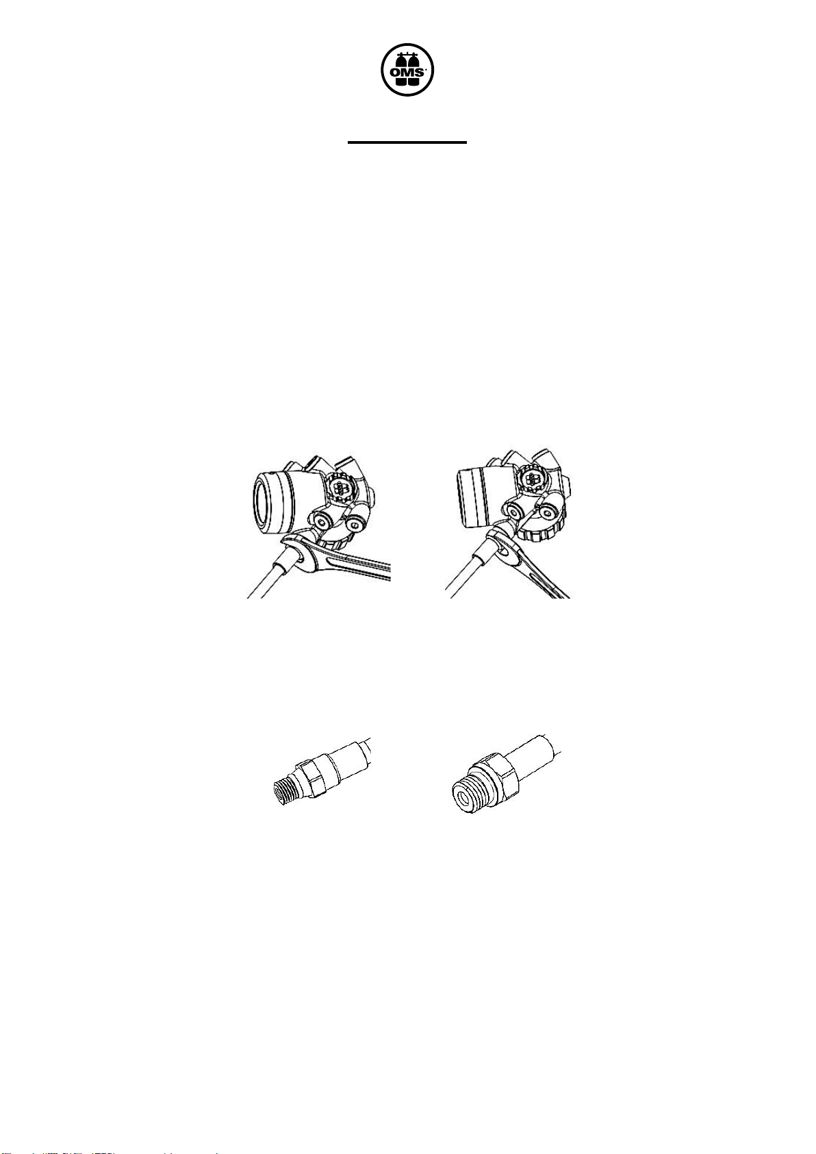
After having determined the type of hose and preferred orientation, remove the port plugs
from first stage regulator by turning them counterclockwise with a 4mm hex key.
Keep the port plugs for possible future use.
Lightly lubricate the hose end threads and O-Ring with Christo-Lube MCG 129 lubricant.
(silicone grease is acceptable only if the regulator is not designated for use with nitrox).
Thread the hose clockwise into the port until secure and thentighten it with an open-end
wrench of the appropriate size, torque of 30 in-lbs.
3/8–24TP
LP HOSE
7/16–20TP
HP HOSE

8
Second stage:Hose male thread (3/8-24) female thread (9/16-18)
Low pressure inflator:Hose male thread (3/8-24)
Diving gauge:male thread (7/16-20)
After all hoses are connected, test the complete regulator assembly by attaching it to a
SCUBA cylinder.
REGULATOR ATTACHMENT TO A TANK
WARNING
Yoke style: Maximum working pressure 3500 psi / 232 BAR
Din style: Maximum working pressure 4500 psi / 300 BAR
Before attaching the regulator to the tank, slowly open, then close the tank valve for a
second, to allow a momentary flow of breathing gas to blow any moisture or contaminants
from the breathing gas opening in the tank valve.
Examine the sealing O-Ring located on the tank valve to ensure that it is not cut, scrubbed,
or deteriorated.
Replace the O-Ring if it is damaged. (FOR YOKE STYLE)
9
Examine the threads in the valve to ensure they are clean and free of burrs or defects that
could damage the threads of your regulator DIN fitting. Examine the sealing O-Ring (As568-
111, N90) located on the DIN first stage to ensure that it is not cut, scrubbed, or
deteriorated. (FOR DIN STYLE)
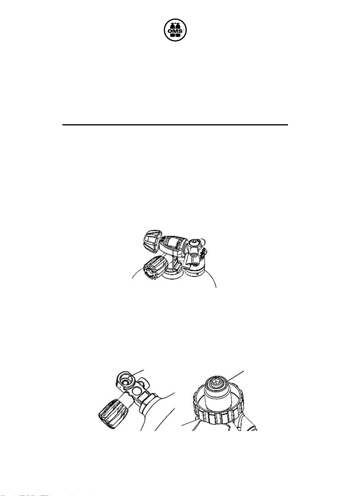
TO ATTACH THE REGULATOR TO THE TANK
Remove the dust protector from the yoke by turning the easy-grip knob in a
counterclockwise direction.
Place the yoke connector over the tank valve, positioned with the seating surface against
the valve O-Ring.
Turn the easy-grip yoke knob clockwise until secure. (FOR YOKE STYLE)
Remove the protector cap from the threads of the regulator DIN connector wheel, and
examine the threads and sealing O-Ring. (AS568-111, N90)

10
Replace the O-Ring if it is damaged. Use care not to cross the threads. Thread the DIN
connector wheel clockwise into the cavity of the tank valve until it is secure. (FOR DIN
STYLE)
Slowly open the tank valve (with the pressure gauge facingaway from you).
Momentarily purge the second stage and then listen to ensure that no breathing gas is
leaking from the regulator or valve connection.
If any leakage is observed, inspect the sealing O-Ring. Replace if damaged or if it does not
seal properly
If gas still leaks, DO NOT USE.
Take the regulator and SCUBA cylinder to an authorized supplier or dealer for inspection
and service.
TO REMOVE THE REGULATOR FROM THE SCUBA
CYLINDER
Close the tank valve and purge all breathing air from the regulator system by pressing the
purge button of the second stage regulator.
Ensure that all pressure has been purged.
Turn the easy-grip yoke knob counterclockwise to loosen and lift the first stage off the tank
valve. (FOR YOKE STYLE)
Turn the DIN connector wheel counterclockwise out of cavity in the tank valve. (FOR DIN
STYLE)
Prevent water from entering the first stage.
Table of contents
Other OMS Diving Instrument manuals


