WARNING! OMS£SERVICE MANUALS ARE TO BE UTILIZED BY OMS TRAINED AND
AUTHORIZED TECHNICIANS ONLY. Improper service and or repair attempts by an untrained or uncertified
person(s) is not authorized by OMS, and could result in equipment failure causing serious injury or death .
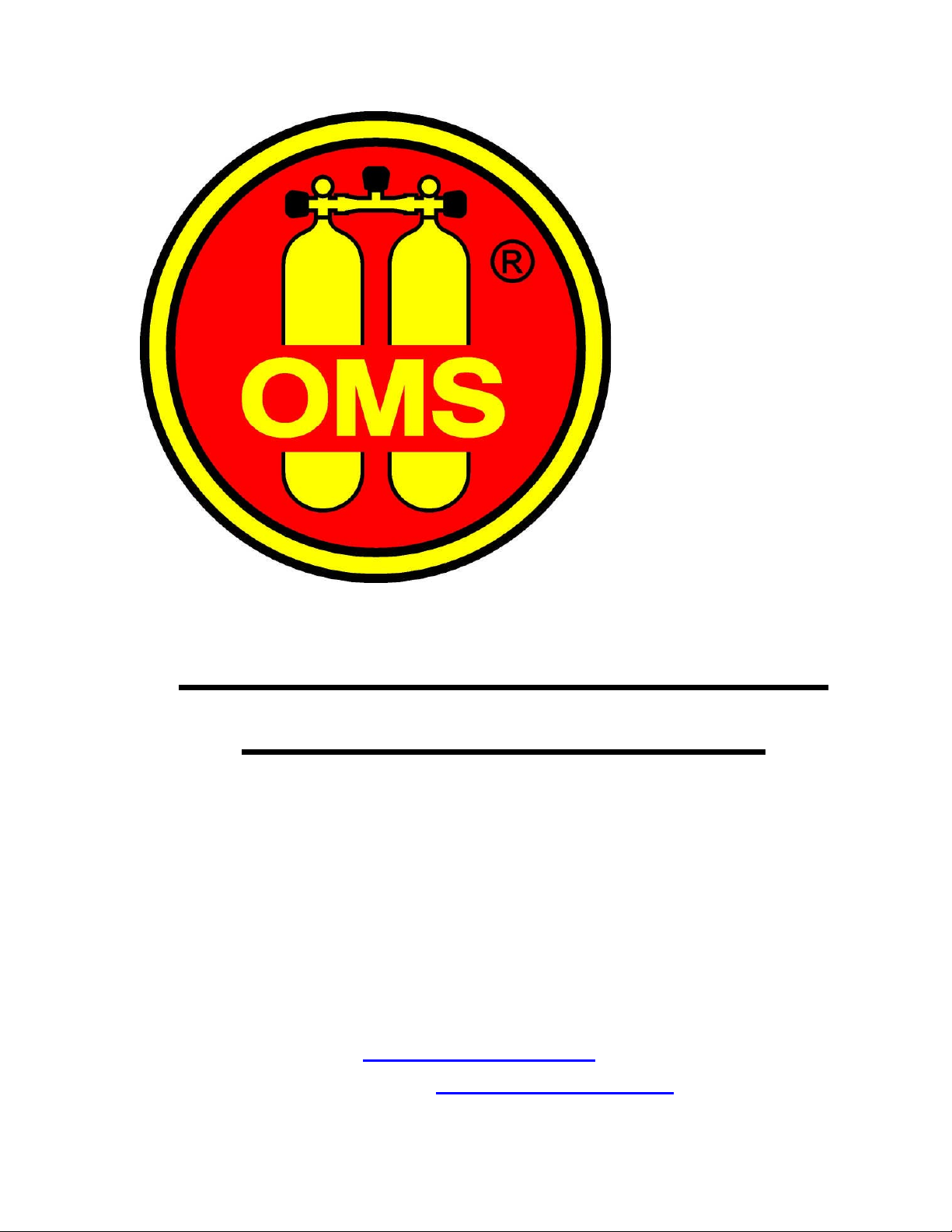
Service Guide for the OMS Workhorse Regulator
Introduction
This manual is to be used only by technicians authorized by Ocean Management
Systems (OMS LLC). It is a guide to assist in the servicing of the OMS Workhorse Regulator
and should be used only after the technician has received sanctioned training on servicing this
specific regulator. It is necessary for the technician to have an understanding of basic
regulator principles, compressed air safety, and the proper use of the tools required. This
manual is not intended to be a complete regulator repair course.
NOTE: Many repair parts may be similar in appearance but have different physical or
chemical properties. Use only parts from OMS repair kits for OMS regulators.
Substituting parts can compromise the function of OMS regulators.
General Guidelines
xOMS regulators should be serviced annually regardless of usage. There are seals
under constant spring tension that must be replaced every year to insure peak
performance. Regulators under heavy use conditions may require more frequent
service.
xThe customer should also understand the importance of a pre-dive inspection of
external regulator parts like hoses and mouthpieces.
xThe customer should be advised of the importance of post dive maintenance as
outlined in the user manual.
xMoisture should never be allowed to enter the inlet of the first stage.
xNever depress the purge button of the second stage while submerged if there is no
pressure from the first stage. This could allow water to enter the demand valve.
x7KHFXVWRPHUVKRXOGXQGHUVWDQGWKDWWKHUHDUHQRµXVHUVHUYLFHDEOH¶SDUWVRU
adjustments inside the regulator. Adjustments or repairs are to be performed only
by authorized technicians.
xNever use aerosol products such as lubricants or cleansers on OMS regulators.
Aerosol propellants can attack rubber and plastic parts.
xA technician encountering any unusual situations or conditions not outlined in this
manual should contact OMS technical support immediately